Abstract
Purpose
This work applies task-driven optimization to the design of non-circular orbits that maximize imaging performance for a particular imaging task. First implementation of task-driven imaging on a clinical robotic C-arm system is demonstrated, and a framework for orbit calculation is described and evaluated.
Methods
We implemented a task-driven imaging framework to optimize orbit parameters that maximize detectability index d′. This framework utilizes a specified Fourier domain task function and an analytical model for system spatial resolution and noise. Two experiments were conducted to test the framework. First, a simple task was considered consisting of frequencies lying entirely on the fz-axis (e.g., discrimination of structures oriented parallel to the central axial plane), and a “circle + arc” orbit was incorporated into the framework as a means to improve sampling of these frequencies, and thereby increase task-based detectability. The orbit was implemented on a robotic C-arm (Artis Zeego, Siemens Healthcare). A second task considered visualization of a cochlear implant simulated within a head phantom, with spatial frequency response emphasizing high-frequency content in the (fy, fz) plane of the cochlea. An optimal orbit was computed using the task-driven framework, and the resulting image was compared to that for a circular orbit.
Results
For the fz-axis task, the circle + arc orbit was shown to increase d′ by a factor of 1.20, with an improvement of 0.71 mm in a 3D edge-spread measurement for edges located far from the central plane and a decrease in streak artifacts compared to a circular orbit. For the cochlear implant task, the resulting orbit favored complementary views of high tilt angles in a 360° orbit, and d′ was increased by a factor of 1.83.
Conclusions
This work shows that a prospective definition of imaging task can be used to optimize source-detector orbit and improve imaging performance. The method was implemented for execution of non-circular, task-driven orbits on a clinical robotic C-arm system. The framework is sufficiently general to include both acquisition parameters (e.g., orbit, kV, and mA selection) and reconstruction parameters (e.g., a spatially varying regularizer).
I. INTRODUCTION
Cone-beam CT (CBCT) is becoming increasingly prevalent for image-guided procedures as a basis for 3D image updates and intraoperative quality assurance. In such procedures, there is a wealth of information available regarding the patient’s specific anatomy including, but not limited to, pre-operative planning images and knowledge of the structures of interest, making the use of CBCT frequently focused on viewing a specific task, such as a bleed, fracture, or implant, within the patient. With knowledge of the imaging task combined with knowledge of the patient, the performance of CBCT can be predicted and optimized. We refer to such prospective design of the acquisition based on imaging goals and the patient-specific anatomy as task-driven imaging. In previous work [1, 2], we optimized orbital parameters of the C-arm and optimized the tilt angle of the orbit in combination with image acquisition and reconstruction parameters. In this work, we extend the task-driven imaging framework for orbit optimization and implement task-driven orbits on a clinical robotic C-arm.
II. THEORETICAL AND EXPERIMENTAL METHODS
A. Task-Driven Imaging
Overall Framework
In interventional imaging, a diagnostic pre-operative CT is readily available and can be used to define a task of interest at a specific location. Alternatively, a CBCT image acquired at the beginning of the procedure can be used to define the task. In either scenario, the task can then be used to estimate the performance of CBCT imaging based on both image acquisition and reconstruction parameters, resulting in improved visualization of the task in the CBCT image. In this work, we optimize parameters defining the orbit of the x-ray source during image acquisition.
Model-Based Reconstruction Method
We focus on the penalized-likelihood (PL) reconstruction algorithm for model-based iterative reconstruction (MBIR) in a form that is compatible with reconstructing images from non-circular orbits. PL is defined by maximization of an objective function:
| (1) |
where L(μ; y) is a likelihood term and R(μ) is a roughness penalty with strength defined by the regularization parameter β. We have chosen to use the quadratic penalty;
| (2) |
where j indexes all voxels and k indexes the voxels in the first-order neighborhood around voxel j.
Task Functions
The task function Htask can be defined by the location, frequency content, and contrast of an object of interest based on a patient-specific anatomical model and clinical knowledge. Here we assume this model is readily available in the form of a pre-operative CT image and choose a specific task therein to form Htask.
Objective Function
We maximize detectability index d′ using a non-prewhitening observer model that includes the task (Htask), spatial frequency response (MTF), and noise-power spectrum (NPS) of the system for any location j within the object:
| (3) |
The MTF and NPS at location j for PL reconstruction with quadratic penalty have been previously derived4 as:
| (4) |
and
| (5) |
Both MTF and NPS in this form are patient dependent, location dependent, and have been shown to accurately predict resolution and noise for quadratic penalties, assuming locally stationary image properties.
Optimization Method
The covariance matrix adaptation-evolution strategy (CMA-ES)3 was chosen as the optimizer to solve for the orbit parameters Ω;
| (6) |
CMA-ES is non-linear, non-convex, and adjusts the covariance matrix of a population with each iteration. Parameters for CMA-ES included a population size of 200, initial σ of 15, and stopping criterion of <10−12 change in d′2. The orbit was parameterized by a series of x-ray source locations, each defined by a rotation angle θn and tilt angle φn for N = 360 source locations. All 360° in θ were used, with each associated φn ∈ [−30° 30°].
B. Experimental Methods
Operation of the Artis Zeego for Non-Circular Orbits
To execute non-circular orbits predicted by the task-driven framework, we used a robotic C-arm (Artis Zeego, Siemens Healthcare) for CBCT imaging. Figure 1 shows the Artis Zeego with two non-circular orbits: the previously proposed “circle + arc” orbit (detailed in Experiment 1 below) and a task-driven orbit. An orbit was parameterized by a series of x-ray source locations defined by a rotational angle and a tilt angle (θ, φ)n for N locations. The robotic C-arm was programmed to move sequentially to each (θ, φ)n location to generate projection images. For image acquisition, automatic exposure control (AEC) was turned off, and exposure settings were set to 102 kV and 0.36 mAs/projection to prevent saturation of the images. The “self-calibration” method in [5] was used for geometric calibration, using 3D-2D registration of the projection data to a previously acquired 3D volume to generate the geometric parameters of the system. The method does not rely on a current geometric calibration and is compatible with non-circular orbits.
Figure 1.
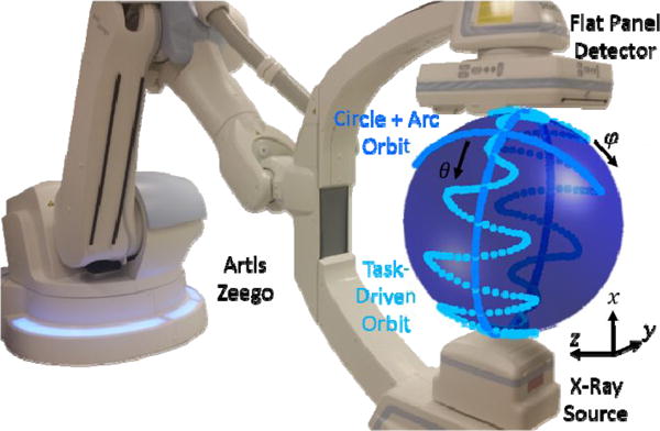
The Artis Zeego robotic C-arm system with movement indicated for the circle + arc orbit and any non-circular task-driven orbit.
Experiment 1: Circle + Arc Orbit for a Simple Task
We first analyzed a simple task emphasizing frequencies along the fz-axis of Fourier space – e.g., discrimination of flat disks oriented parallel to the central axial plane, as shown in figure 2. In CBCT it is well known that a circular orbit results in incomplete sampling of Fourier space, resulting in a spatially varying “null cone” around the fz-axis.6 The circle + arc orbit is one example of a previously proposed non-circular orbit that more completely samples Fourier space,7 and thereby increases d′ for this task, which emphasizes precisely those frequencies on the fz-axis. To emulate this task in an imaging phantom, we inserted two stacks of alternating Teflon and polyethylene discs in a head phantom and imaged the phantom on the Artis Zeego using the circle + arc orbit. The orbit consisted of a 200° short scan in θ (holding φ = 0°) as the ‘circle’ and a 60° arc in φ (holding θ = 0°) as the ‘arc’. A total of 262 projections were obtained, resulting in 92 total mAs. The CBCT image was reconstructed using the PL algorithm described above with β = 104, 600 iterations, 0.5 mm isotropic voxels, and for the Poisson-likelihood model we estimated the bare-beam fluence to be 104 photons per detector element. A 200° circular short scan (201 projections, 70 mAs) was reconstructed for comparison to a nominal circular orbit.
Figure 2.
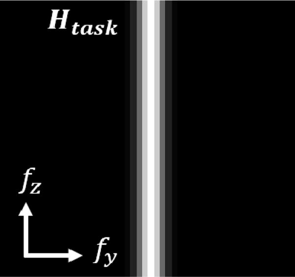
Task function Htask for Experiment 1, consisting of frequencies along the fz-axis of Fourier space.
To measure improvement in task visualization, an up-sampled fit to the edge spread between discs was computed from voxels around each disc edge. The fitting function was a 4-parameter Gaussian error function and the edge spread widths are reported in mm as the full-width at half max of the point spread function obtained from differentiating the Gaussian error function. This was done for the stack of disks on the left side of the head and for the uppermost 8 edges. Streak artifacts evident between the stacks of discs were quantified as the relative deviation of pixel intensities from the mean of a background region of interest.
Experiment 2: Orbit Optimization for a Complex Task
To emulate a more complex task within a realistic anatomical context, we modeled the task of cochlear implant visualization in terms of high frequency content in the fz-fy plane at the location of the cochlea as seen in figure 3. High frequency content in a coronal plane (as opposed to an axial plane) creates a non-trivial optimization. We digitally added the high-density implant with attenuation coefficient μ = 0.1 mm−1 to a CT image of a head phantom consisted of a human skull encased in tissue-equivalent plastic (figure 3a, 3b). The orbit optimizing d′ for this task was computed using the method described above, and we used a Siddon forward projector implemented on GPU to generate projections defined by the orbit and Zeego geometry. The image was reconstructed as described above with β = 105, 300 iterations, 0.2 mm isotropic voxels, and bare-beam fluence of 105 photons. The result was compared to a reconstruction of projections generated from a circular orbit using the same reconstruction algorithm and parameters.
Figure 3.
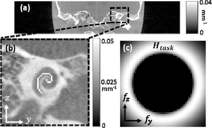
(a) CT image of the anthropomorphic head phantom, (b) digitally added cochlear implant in the coronal plane with μ = 0.1 mm−1, and (c) task function Htask corresponding to the cochlear implant.
III. RESULTS AND BREAKTHROUGH WORK
A. Experiment 1: Circle + Arc Orbit for a Simple Task
Addition of the arc to a nominal circular orbit increased d′ by a factor of 1.20 for the task shown in figure 2. The 3D edge spread measurements of the discs (figure 4a) show a reduction of 0.71 mm at the furthest edge, with 2.35 mm for the circular orbit and 1.64 mm for the circle + arc orbit. The magnitude of streaking artifact between the two stacks of discs in the coronal plane was also reduced, with the relative deviation from the background decreasing from 6.84 ± 0.29% to 5.77 ± 0.27% (p < 0.001) for the circle + arc orbit. Image reconstructions from the nominal circular orbit and the circle + arc orbit are seen in figure 4b and 4c respectively and show an improvement in the resolution of the edges of the circular discs, specifically for those further from the central slice (i.e. increasing in the z-direction). This simple experiment illustrates the task-driven concept in a simple form for which CBCT sampling is improved with respect to a highly idealized task, and it shows the ability to execute non-circular orbits on a robotic C-arm.
Figure 4.
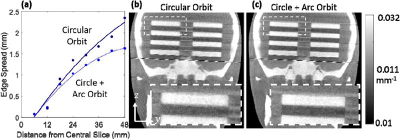
(a) Edge spread measurements for the alternating disc phantom representing a task of frequencies on the fz-axis. ESF width is plotted for increasing z distance from the central slice for the circular and non-circular orbit. (b) Coronal slice from PL reconstruction of a circular orbit. (c) The same slice for the circle + arc orbit, showing improved resolution of the disc edges in the z-direction.
B. Experiment 2: Orbit Optimization for a Complex Task
Figure 5a shows the optimized orbit for the cochlear implant task. The orbit is shown to favor the highest allowable degree of tilt angle over the first half of the orbit at +30° and the second half at −30° to obtain complementary views. These angles correspond to views with the least attenuation through the phantom at the location of the cochlea and increase the MTF at high frequencies in the fz-fy plane (figure 6c) as compared to a circular orbit (figure 5b). The d′ value for this orbit increased by a factor of 1.83 over that for the nominal circular orbit, and the reconstructed images (figure 6) show improvement in the visualization of the cochlear implant for the task-driven orbit with better discrimination between the implant and adjacent bone and increased contrast between the implant and background soft tissue.
Figure 5.
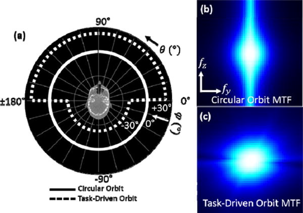
(a) Task-driven vs circular orbit. The task-driven orbit favors complementary views at high tilt angles. (b) MTF for the circular orbit at the task location. (c) Same for the task-driven orbit, which increases the MTF at the higher frequencies of interest.
Figure 6.
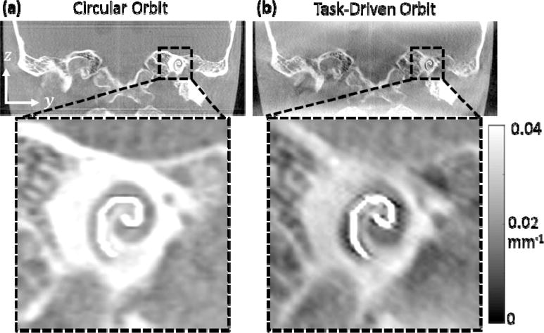
(a) PL reconstruction from a circular orbit and (b) from the task-driven orbit shown in figure 5. Improved visualization of the cochlear implant is apparent for the task-driven orbit.
IV. DISCUSSION and CONCLUSION
This work shows the successful implementation of task-driven, non-circular orbits on a clinical robotic C-arm system. Task-driven, non-circular orbits were successfully executed on a clinical robotic C-arm and reconstructed using model-based image reconstruction in combination with geometric “self-calibration”. The framework is flexible in terms of the system parameters included in Ω, which can be expanded to include other technique factors such as view-varying mA as well as reconstruction parameters such as regularization. Future work includes other pertinent interventional imaging tasks implemented on the Artis Zeego and optimizing for multiple task functions and locations.
Acknowledgments
This research is supported by NIH Grant No. R01-EB-017226 and Siemens Healthcare (AT, Forcheim, Germany). The authors thank Mr. Robert Meyer (Siemens Healthineers) and Ms. Robin Belcher (Department of Radiology, Johns Hopkins University) for assistance with the imaging system.
References
- 1.Stayman JW, Siewerdsen JH. Task-based trajectories in iteratively reconstructed interventional cone-beam CT. (Proc. 12th Int. Meet. Fully Three-Dimensional Image Reconstr).Radiol Nucl Med. 2013:257–260. [Google Scholar]
- 2.Gang GJ, Stayman JW, Ehtiati T, Siewerdsen JH. Task-driven image acquisition and reconstruction in cone-beam CT. Physics in medicine and biology. 2015;60(8):3129–50. doi: 10.1088/0031-9155/60/8/3129. [DOI] [PMC free article] [PubMed] [Google Scholar]
- 3.Hansen N. Towards a new evolutionary computation. Springer Berlin Heidelberg; 2006. The CMA evolution strategy: a comparing review; pp. 75–102. [Google Scholar]
- 4.Stayman JW, Fessler JA. Regulariztion for uniform spatial resolution properties in penalized-likelihood image reconstruction. IEEE transactions on medical imaging. 2000;19(6):601–15. doi: 10.1109/42.870666. [DOI] [PubMed] [Google Scholar]
- 5.Ouadah S, Stayman JW, Gang JG, Ehtiati T, Siewerdsen JH. Self-calibration of cone-beam CT geometry using 3D-2D image registration. Physics in medicine and biology. 2016;61(7):2613. doi: 10.1088/0031-9155/61/7/2613. [DOI] [PMC free article] [PubMed] [Google Scholar]
- 6.Bartolac S, Clackdoyle R, Noo F, Siewerdsen J, Moseley D, Jaffray D. A local shift-variant Fourier model and experimental validation of circular cone-beam computed tomography artifacts. Medical physics. 2009;36(2):500–12. doi: 10.1118/1.3062875. [DOI] [PMC free article] [PubMed] [Google Scholar]
- 7.Wang X, Ning R. A cone-beam reconstruction algorithm for circle-plus-arc data-acquisition geometry. IEEE transactions on medical imaging. 1999;18(9):815–24. doi: 10.1109/42.802759. [DOI] [PubMed] [Google Scholar]


