Abstract
Dexterous continuum manipulators (DCMs) have been widely adopted for minimally- and less-invasive surgery. During the operation, these DCMs interact with surrounding anatomy actively or passively. The interaction force will inevitably affect the tip position and shape of DCMs, leading to potentially inaccurate control near critical anatomy. In this paper, we demonstrated a 2D mechanical model for a tendon actuated, notched DCM with compliant joints. The model predicted deformation of the DCM accurately in the presence of tendon force, friction force, and external force. A partition approach was proposed to describe the DCM as a series of interconnected rigid and flexible links. Beam mechanics, taking into consideration tendon interaction and external force on the tip and the body, was applied to obtain the deformation of each flexible link of the DCM. The model results were compared with experiments for free bending as well as bending in the presence of external forces acting at either the tip or body of the DCM. The overall mean error of tip position between model predictions and all of the experimental results was 0.62±0.41mm. The results suggest that the proposed model can effectively predict the shape of the DCM.
Index Terms: Dexterous continuum manipulators, compliant joints, partition approach, Cosserat rod theory
I. Introduction
Minimally invasive procedures are popular in current clinical diagnoses and treatments because of improved safety and faster recovery as compared to open surgery [1]. Typically, such surgeries require specific tools such as biopsy forceps or ring curettes to enter a small space and perform the surgery. Traditional rigid tools cannot provide enough flexibility and maneuverability to reach all necessary targets without adversely interacting with the surrounding tissue.
In this paper, we focus on two motivating minimally invasive lesion-removal applications in confined anatomical space. Each procedure—treatment of osteolysis and skull base surgery—utilizes a dexterous continuum manipulator (DCM) with a large lumen for manipulation and tool insertion. The less invasive treatment of osteolysis (defected bone tissue) behind the acetabular cup during hip revision surgery is performed through the screw holes of the well-fixed acetabular implant [2]. Conventional rigid tools only allow removing less than 50% of the defected tissues [3]. At the skull base, cholesterol granulomas in the petrous apex will cause hearing loss without complete removal. Drainage and ring curettes are usually used cooperatively to perform the aeration; conventionally, an unsteerable drainage tube and a rigid curette inserted through the limited entry port cannot perform complete removal. The performance of both motivating minimally invasive surgeries is limited because the reachable workspace through the small entry port is severely restricted by a rigid tool.
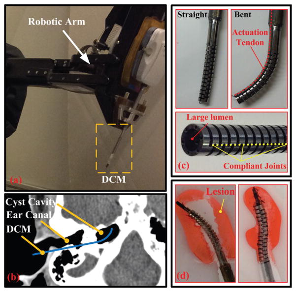
Previously, we have developed a notched DCM with a large lumen machined with a series of compliant joints to assist these two typical surgeries [2]–[4], where the skull base surgery is taken as an example shown in Fig. 1. Preliminary kinematic models of the variable-curvature DCM described free space movement with acceptable accuracy [5]. However, the empirical kinematic model was not accurate in the presence of external forces. Previous work [6] developed a physical model assuming revolute joints to describe the deformation of DCM. However, this did not effectively capture friction, only worked well for the bending phase, and underestimated the hysteresis. The hysteresis, likely caused by the friction in the bending and unbending cycle described in [7], should be addressed carefully. Rather than a kinematic model, a mechanical model may be more suitable to predict DCM deformation, especially in the presence of tendon interaction and external forces.
Fig. 1.
DCM integrated with a robotic arm for an example application to skull base surgery [4]: (a) DCM attached to a robotic arm; (b) DCM path to the petrous apex through the tympanic bone for skull base surgery; (c) the straight and bent DCM with large lumen. Also shown is the location of compliant joints; (d) lesion (red color) removal using a 2D phantom of a cross section of petrous apex, where DCM is interacting with the boundary of phantom.
The literature documents several mechanical models using the principle of virtual work [8], [9], Cosserat rod theory [10], [11], and other approaches [12], [13] without considering the friction. Kato et al. [14] built a model to describe the deformation of an endoscope considering the friction force. However, these modeling methods mainly focus on robots with a continuum rod or tube as the backbone significantly different from our DCM with notched tube as the backbone and cannot be used directly to describe our notched DCM with compliant joints. Du et al. [15] designed a similar manipulator with V-shaped units, and proposed a kinematic model based on Timoshenko beam theory, but did not explore the effects of friction force and external forces. York et al. [16] designed a needle-sized robot and built a static model with friction force to describe only the free bending. To our knowledge, the existing literature lacks models of notched DCMs with compliant joints subjected to the tendon force, friction force, and external forces and did not predict the hysteresis of DCM.
In this paper, we propose a partition method for notched DCMs with compliant joints and then build a general and comprehensive 2D mechanical model for tendon actuated DCMs. The model considers the geometric structure to describe the deformation accurately in the presence of tendon interaction and external forces. Section II reviews the DCM and its workspace and capabilities. Section III introduces a partition approach for the notched DCM. Section IV reviews Cosserat rod theory and calculates the parameters for general flexible and rigid links, and describes the particular mechanical model. Section V presents the experimental results to validate the proposed model. Section VI discusses the sources of error, and illustrates the variation of notches. Finally, Section VII presents the conclusions. The main contribution of this paper is the development of a general modeling approach for notched 2D DCMs including the tendon force, friction force, and external force.
II. Overview of DCM With Compliant Joints
A. Structure
The 2D DCM was first developed in [2] for less invasive removal of osteolysis, and later was extended for skull base surgery (Fig. 1). The DCM is made of two superelastic nitinol tubes, which are cut axially through the outer wall of the inner tube and the inner wall of the outer tube to create a through channel. They are then assembled with an interference fit and cut using electrical discharge machining (EDM) to create crossed notches, thereby forming compliant joints. Actuation tendons are inserted inside the through channels and fixed to the tip of the DCM. When the actuation tendon is pulled or released, the DCM is bent or recovered.
B. Workspace and Payload Capability
Previously, we showed that a kinematic model with pin joints at the center of compliant joints has an acceptable accuracy for the treatment of osteolysis application [5]. Based on this, a group theoretic convolution framework was adapted to describe the workspace [17]. Assuming arbitrary external forces and no self-collisions, the workspace approximates a banana-shaped distribution covering about 1200mm2 [17]. This workspace is for a particular pose of the base of the DCM; when integrated with a robotic arm, the workspace can be increased by translating and rotating the base of the DCM.
Given a specific notch pattern and length as described in [2], the DCM applied 1N tip force on a stationary object when its tendon was pulled 25N. As a very conservative estimate, the payload capability at the tip of DCM, therefore, can be larger than 1N.
III. Partition Approach of DCM with Compliant Joints
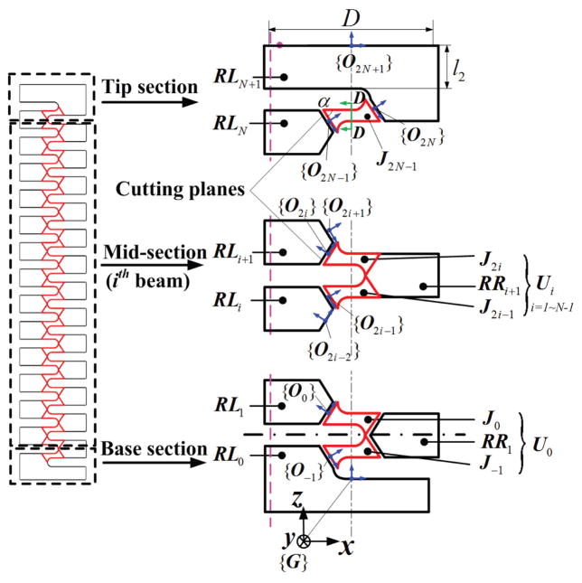
Consider a notched DCM with 2N+1 compliant joints, such as that (N=13) described in Section II for example. It has a series of rectangular crossed notches with round corners to create compliant joints (Fig. 2). Our approach partitions the DCM into both flexible and rigid links and uses beam theory to calculate the deformation of flexible links. The computed deformation of each link approximates the deformation of the DCM. We assume the DCM is built from three interconnected sections: tip, mid, and base (Fig. 2). Each section is composed of a left rigid link (RLi), and flexible links (J2N−1 and Ui): the tip section includes J2N−1; the mid-section includes U-shaped link Ui; the base section includes U0. Each typical U-shaped link Ui includes both a right link (denoted as RRi+1) and flexible links (denoted J2i−1 and J2i).
Fig. 2.
Diagram of partition method: The cutting planes are defined and the red and black parts stand for the flexible links and the rigid links, respectively.
Because the half circle structure (Fig. 2, near the cross section D-D) is shared by two flexible links, we partition the DCM at each joint by using two cutting planes: parallel to Y axis in {G} (Fig. 2) and going through the middle points of the left and right half circles. This choice of portioning defines the largest flexible link possible. The deduction of α, the angle between the cutting plane and the notch plane (Fig. 2), is introduced in Section IV-B (1). Notably, J2i−1, J2i and RRi+1 can be integrated into a single U-shaped link Ui (Table I).
TABLE I.
Description of separated links
| Link | J2i−1 | J2i | RRi+1 | Ui | ||
|---|---|---|---|---|---|---|
| Projection & neural axis |

|

|
|

|
||
| Angular rate of change | u;j*(s) | −u;j*(s) |
|
|
IV. Mechanical Model With Tendon Actuation And Parameters Calculation
Based on the partition, we aim to use beam theory to describe the deformation of flexible links (Part B–F). The D-H method will integrate the rigid links and define the kinematics of the three sections to obtain the whole DCM deformation (Part G).
A. Review of Classic Cosserat Rod Theory
Cosserat rod theory is a good choice to model the links because it considers the shear and axial force, especially for short beams like the flexible links (Fig. 2). For classic Cosserat rod beam theory, ordinary differential equations (ODEs) are derived from the rod kinematics, equilibrium equations, and constitutive laws [10], [11]. For an arbitrary arc length s of the beam, the homogeneous transformation matrix from the base is:
| (1) |
For the typical U-shape link Ui in Fig. 2:
| (2) |
where vi(s) and ui(s) are linear rate and angular rate of change of gi(s), expressed as follows:
| (3) |
Here, Kse(s) and Kbt(s) are the stiffness matrices for shear/extension and bending/torsion respectively.
| (4) |
where E is the Young’s modulus and G is the shear modulus; A(s) is the area of the cross section; Ixx (s) and Iyy(s) are the second moments of area; Jzz(s) is polar moment of inertia. Because the DCM only deforms in the bending plane, EIyy(s) = +∞ and EJzz(s) = +∞.
If an external force or moment is applied at the mid-point of an arbitrary segment, then ni(s) and mi(s) (Eq. 2–3) in the left and right side of the specific arc length, σ, can be calculated as follows:
| (5) |
Here, FBRi is an external force at any point (denoted as Point B); lBRi is the moment at Point B; and lFBRi is the moment resulting from FBRi.
According to Eq. 2, given the structural parameters and the boundary conditions, the ODEs can be solved. The critical structural parameters for flexible and rigid links, , Ixx(s) and A(s) will be discussed and calculated in Subsection B–D. The boundary conditions for each section will be given in Subsection F.
B. Geometrical Parameters of Flexible Links - J2i−1 and J2i
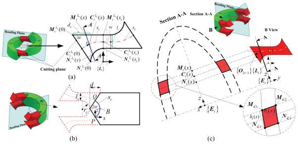
The DCM can only deform in the 2D bending plane, so we can project J2i−1 to the bending plane (Fig. 3(a)).
Fig. 3.
Diagram of flexible link (red color), rigid link (green color) and the flexible link’s cross section: (a) Projection of flexible link to the bending plane; (b) Projection of rigid link to the bending plane: the blue line indicates the virtual neutral axis with arc length, sr. P and Q are the intersection points between the neural axis and two cutting planes with the angle, 2α; (c) Diagram of cross section for the flexible link, J2i−1.
(1) Determination of cutting plane and parameters
In order to determine the cutting plane, we choose the middle point of circular notch as one point in the cutting plane and then calculate the angle α between the cutting plane and notch plane (Fig. 3(a)). We make two assumptions: 1) the neutral axis of flexible link lies at the structural center; 2) the tangent vector of the neutral axis is perpendicular to the beam cross section at the initial reference configuration before the deformation.
With regard to the first segment (Fig. 3(a)), de is defined as . Points for the base edge and top edge at the coordinate {Li} with respect to the arc length s of neural axis are expressed as
| (6) |
| (7) |
where t = s / st (0 ≤ s ≤ st, 0 ≤ t ≤ 1), ls is the height of second segment. Based on the assumption 1, the neutral axis can be calculated as .
Based on the assumption 2, the unit tangent vector denoted as of neutral axis and the unit tangent vector denoted as of the cross section should conform to at where s = 0, so de can be calculated. The curvature of neutral axis can be derived as
| (8) |
By integrating the arc length, st can be calculated as
| (9) |
Next the angle α between the notch plane and cutting plane (Fig. 3(a)) can be calculated as
| (10) |
which finally defines the location of cutting plane.
The second segment with arc length w and height ls is a straight line, so the curvature . Due to the rotational symmetry to the first segment, the curvature of the third segment is . Then, for J2i−1, , the angular rate of change of g(s) in Eq. 3, can be expressed as Eq. 11 and its linear rate of change is .
| (11) |
Also due to the mirror symmetry, the angular and linear rate of change for J2i is and .
(2) Calculate I(s) and A(s)
The moment of inertia I(s) and cross sectional area A(s) are used to calculate the stiffness (Eq. 4). Because the deformation only happens in the bending plane, the stiffness along the Y and Z axes are Iyy (s) = (s)Izz = +∞.
The cross section for the first segment is the intersection of Section A-A and DCM forming an elliptical ring (Fig. 3(c)). We simplify this cross section to a parallelogram. The first segment has two symmetric flexible parts to Y-Z plane in the local coordinates {Ei}, and its moment of inertia, I1(s), and area, A1(s), are calculated as:
| (12) |
The third segment has rotational symmetry to the first segment, therefore, its moment of inertia is I3 (s) = I1 (2 · st + w − s) and its cross-sectional area is A3 (s) = A1 (2 · st + w − s).
The cross section of the second segment is a rectangle. This segment’s moment of inertia and cross-sectional area are and A2 (s) = b2 (s) · ls respectively. Here, ls is the height of the cross section, and b2 (s) is the width of the cross section.
The moment of inertia and the cross-sectional area of the whole link J2i−1 can be expressed as follows:
| (13) |
C. Geometrical Parameters of Rigid Links- RRi+1
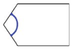
We assume the rigid link, RRi+1, has a rotational and shear stiffness of +∞, and RRi+1 ’s curvature is first-order continuous with respect to its arc length. Therefore, the rigid link, RRi+1 in the link Ui (one link in the mid-section) is defined as an arc starting at P and ending at Q with an infinite stiffness (Fig. 3(b)).
The curvature, κPQ, at Point P and Q is the same as in Eq. 8. Point B (Fig. 3(b)) is the mid-point of the arc with an unknown curvature, κB. We linearize the curvature at any specific arc length s as:
| (14) |
| (15) |
Projecting the half arc onto the Z axis (Fig. 3(b)), we can obtain the Eq. 15. Then substitute Eq. 14 to Eq. 15, κB can be calculated, as well as κr(s). The arc length, sr, is derived by integrating inverse curvature (Eq. 14) from P to B.
Deriving Eq. 14 defines the curvature with respect to the specific arc length in Eq. 16. The resulting angular rate of change of g(s) with respect to s can be expressed in Eq. 17.
| (16) |
| (17) |
D. Geometrical Parameter of U-shaped Links - Ui
As shown in Table I, each typical link, Ui, is composed of J2i−1, J2i and RRi+1. We denote the structural parameter of Ui as follows:
| (18) |
| (19) |
Finally, we derive the structural parameters of each link, which are used in Eq. 3–4 when solving the ODEs in Eq. 2.
E. Model Assumptions and DCM Configuration
The proposed mechanical model assumes: 1) deformation only occurs in the bending plane (X-Z plane), meaning the rotational stiffness along the X/Z axis is +∞; 2) the clearance between the tendon and the channel is ignored; 3) the tendon is defined as a string, which cannot resist bending and/or torsion; and 4) the non-actuating cable is not tensioned and imparts neither force nor friction on the DCM. These assumptions will be used in the following deductions.
We consider a typical section configuration with odd compliant joints (Fig. 2). To be more general, there are four types of section configurations with even or odd compliant joints.
F. Tendon Coupled Model
We use Cosserat rod theory to describe each section, given the proximal tendon force, external force and enough boundary conditions, the deformation of each link can be solved, then the whole deformation of DCM can be derived. In order to build the real boundary conditions, the tendon interaction will be illustrated below.
(1) The tip section
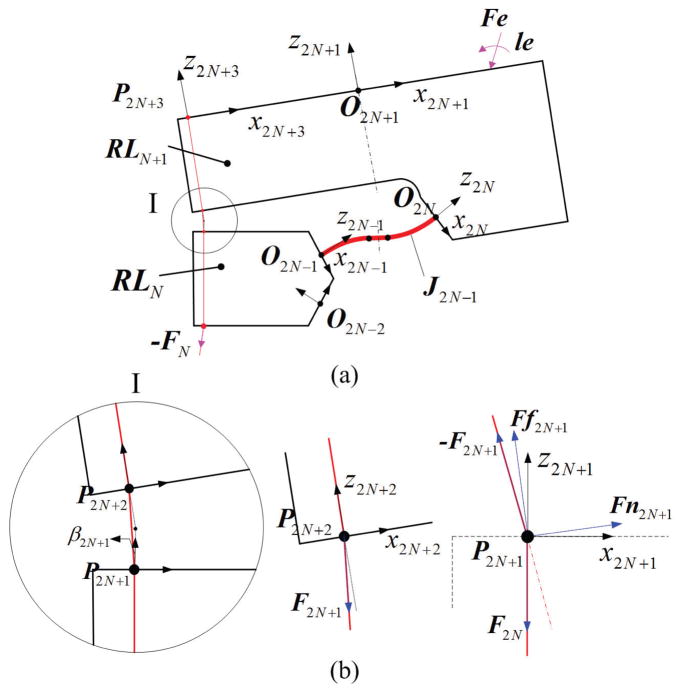
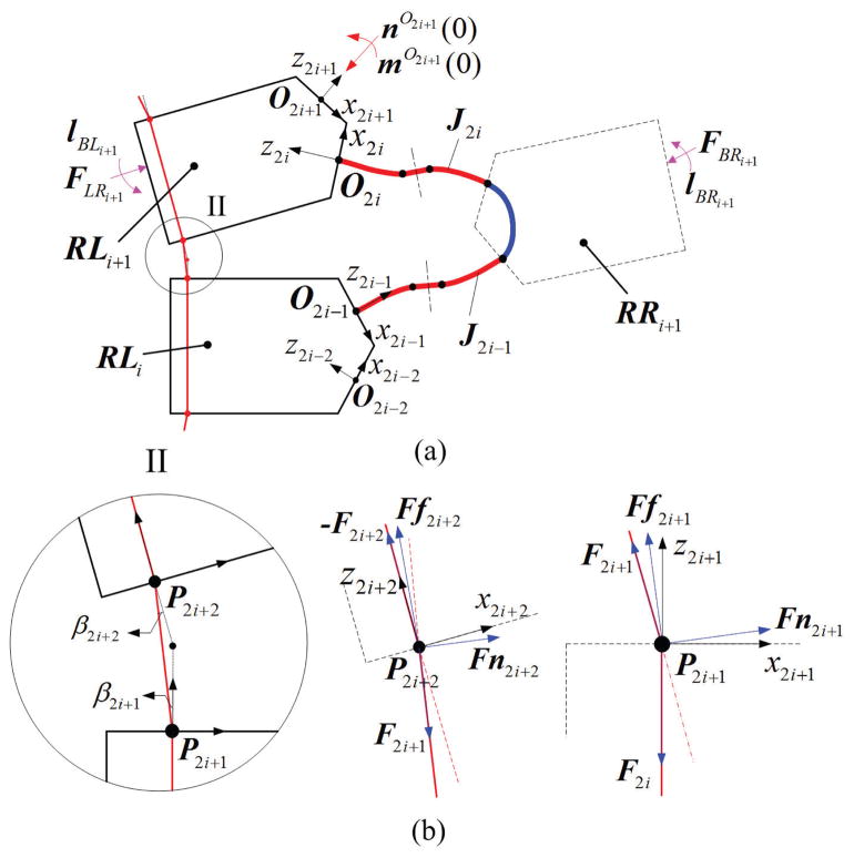
Fig. 4(a) shows the bending plane of the tip section, where the start and end coordinates of the flexible link are defined as {O2N−1} and {O2N}.
Fig. 4.
Diagram of tip sections coupled with the tendon: (a) shows the projection of tip section; (b) show the free body diagrams of tendon at P2N+2 and the sharp corners P2N+1, where β2N+1 is denoted as the relative angle between two segments of tendon.
a) Tendon interaction at P2N+2
The tendon is fixed at P2N+3, then goes through the channel and notch, and interacts with the rigid link RLN+1 at P2N+2 and P2N+1 (Fig. 4). The interaction at P2N+1 is only applied to the rigid part RLN, affecting the deformation of the next beam in the mid-section, not J2N−1 or UN in the tip section. The N-th beam therefore, is subjected to F2N+1 at P2N+2.
b) Section property and boundary conditions
For J2N−1 in Fig. 4(a), the total arc length sl is 2 · st + w, where st can be calculated in Eq. 9. Then the initial parameters are defined as and in Eq. 11.
The boundary conditions, two at s = 0 and two at s = st (for Eq. 2), for the top section are defined as follow:
| (20) |
where pN(0) and RN(0) are the position and orientation at the s = 0 ; nN(sl) and mN(sl) are the internal force and moment at the s = sl. Here Fe and le are the external force and moment applied at the rigid link RLN+1, rO2NP2N+2 and rO2NPE are the distance for the point of force to {O2N}.
So given Eq. 23 and the distal tendon force F2N+1, the ODEs in Eq. 2 can be solved to derive the beam configuration.
(2) The mid-section
The mid-section is composed of a series of U-shaped link Ui. The bending plane of Ui in the mid-section starts at O2i−1 and ends at O2i (Fig. 5(a)).
Fig. 5.
Diagram of mid-section coupled with the tendon: (a) shows the mid-section with Ui; (b) show the free body diagrams of tendon at the sharp corners- P2i+2 and P2i+1, where β2i+2 and β2i+1 are denoted as the relative angle between two segments of tendon.
a) Tendon interaction at P2i+3 and P2i+2
The tendon interacts with RLi+1 at P2i+3 and P2i+2 respectively, assuming that the tendon channel in the rigid link remains straight (Fig. 5). Since the friction force is proportional to the normal force, we assume no friction for the tendon inside the rigid link channel. Only the contact points at the border of the channel have a normal force component and, therefore, friction force. Take P2i +2 as an example: we assume that the direction of normal force lies in the middle of two tendon tensions −F2i+2 and F2i+1, then the friction force is perpendicular to the normal force. If we denote the angle between −F2i+2 and z2i+2 as β2i+2, then the angle between Ff2i+2 and z2i+2 is β2i+2/2. So we can obtain the free body diagram of RLi+1 and tendon at P2i+2 (Fig. 5(b)). Similarly we can also get the free body diagram of RL i+1 and tendon at P2i+3 (P2N+1). The force balance equations for the tendons are:
| (21) |
where Ff2i+3 and Ff2i+2 are the friction force; and Fn2i+3 and Fn2i+2 are the normal force. Thus, Ui is subjected to Fn2i+3, Ff2i+3, Fn2i+2 and Ff2i+2. It is noticeable that F2i+3 is equal to F2N+1.
b) Section property and boundary conditions
The total length of Ui is sl = 4·st + 2·ls +sr(Fig. 5(a)). ODEs are the same with Eq. 2, where i=1~N−1, and the reference configuration and can be obtained from Eq. 18–19. The boundary conditions are
| (22) |
Here in the right side of ni(sl), the first term is the force transformed from the last link, the middle terms are the forces at P2i+3 and P2i+2, the last term is the external force applied at RLi+1; while in the right side of mi(sl), term I is the moment transformed from the last link, term II is the moment transformed from the force in the last link, terms III and IV are the moments from the forces at P2i+3 and P2i+2, term V is the external moment applied at RLi+1. And rO2iP2i+3 and rO2iP2i+2 are the distances for the point of force to O2i.
Given Eq. 22, the ODEs in Eq. 2 can be solved when we substitute Eq. 21 for Eq. 22. Therefore, the normal force, friction force and beam configuration can be derived.
(3) The base section
Fig. 5(a) with i=0 also shows the bending plane of base section, where the start point and end point of flexible link are defined with O−1 and O0. The tendon interacts with the rigid link at P2 and P3. So the elastic link is subject to the normal force Fn2 and Fn3, and the friction force Ff2 and Ff3. This section has the same boundary conditions with Eq. 22 where i=0. As shown in Fig. 5(b), F0 is the proximal force we usually apply, whose magnitude can be solved as
| (23) |
where β1 the angle between −F1 and F0.
G. DCM Kinematics
Because we have assumed that the DCM is composed of a series of interconnected left rigid links (RLi) and flexible links (J2N−1 or Ui). A series of transformation matrices based on the D-H method define the homogenous matrix from the tip to the base as
| (24) |
Here, and are the tip position and orientation in the global coordinates {G}; terms I–III are the transformation matrices of base section, mid-sections and tip section, respectively; is the transformation matrix of each link Ui in the mid-section expressed using Eq. 25, which can be derived from the solution of each link in Subsection F- (1)–(3); is the transformation matrix of each left rigid link RLi.
| (25) |
According to the above deduction, given the distal tendon force F2N+1, Eq. 25 can be derived by numerically solving the statics of each section of DCM, finally the proximal force F0 can be calculated using Eq. 23, and the shape of DCM can be calculated using Eq. 24 based on kinematics, respectively.
H. Consideration of Friction Force
We consider both static and kinetic friction. Subramani et al. [18] proposed a method for modeling the friction force in catheter-like manipulators. We extend their method to match the structure of our DCM. Here we use a Coulomb model of the friction force. We assume that the static friction coefficient equals the kinetic friction coefficient, μc, which is constant for all the cases.
In our model when the DCM is bent, we assume the friction force is always toward the base section with the kinetic friction +μc · Fni. Before starting to release the tendon, it is assumed that there is no relative movement between the tendon and the channel, and the friction force at the contact point remains +μc · Fni.
When the DCM starts to unbend by releasing the tendon tension, the direction of the friction force at all contact points will not change to −μc ·Fni immediately. The tension of the tendon will release from the proximal to the distal end. Therefore, the friction force gradually changes from the first contact point P1 (Fig. 5(b) with i=0) to the last contact point P2N+1 (Fig. 4(b)) point by point. At the m-th contact point, before the start of relative movement between the tendon and channel, it will stick to the original position only with the change of static friction starting from +μc · Fni; while when it starts to slide along the channel, the direction of friction force will become negative, then the friction force will be −μc ·Fni. After the relative slide occurs at all the contact points, the friction force of all the contact points will be −μc · Fni. So for all the contact points, the friction forces will be
| (26) |
where i is the i-th contact point (i =1~ 27), m is the m-th contact point which has the transition situation; η is a coefficient indicating the change of static friction before the relative movement. By adjusting η, the friction force is calculated, then the boundary conditions in Subsection F can be derived.
V. Experimental Validation and Results
Young’s modulus of nitinol is highly nonlinear with temperature and dependent on manufacturing processes; additionally, the developed model assumes an infinite stiffness for the rigid links. Therefore, we calibrated an equivalent Young’s modulus and friction coefficient using an experimental setup described in the following subsection. We performed experiments to compare the model with experimental deformations of the DCM for the following scenarios: 1) with tip force only, 2) with tendon force only, and 3) with tendon force and external tip/body force.
A. Experimental Setup
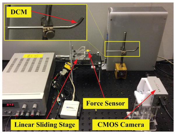
The DCM was fixed to a magnetic support block. The actuation tendon, a 0.25mm steel stripe (McMaster, USA), was attached to the distal tip of the DCM. The proximal side of the tendon was attached to a force sensor (Futek LSB200, USA) fixed to the linear stage (M-UMR8.25A, Newport, USA) with 0.01mm accuracy. A CMOS camera (PixeLINK PL-B774F, USA) was mounted on an optical platform table.
During the experiments, the linear stage was controlled manually to pull/push the tendon with a slow speed (nearly <0.06mm/s) to guarantee a quasi-static scenario, and the tendon force was transferred to the computer using the data acquisition card. When the force reached a desired value, the DCM image was captured by the camera. The images were then processed to calculate the shape of the DCM using a 2D/3D registration method [19]. A DCM made from nested nitinol tubes with 14 pairs of notches [2] was used for the experiments.
B. Calibration of the Equivalent Young’s Modulus
To find the equivalent Young’s modulus E in Eq. 4 for the DCM, we carried out six groups of experiments with a series of weights - 10g, 20g, 50g, 70g, 100g and 150g. Each weight was applied from the tip at the position [−0.5dt,0,0] in the local coordinates {O2N+1}. Each group was repeated ten times. Next, using the model described in Section IV, we found an equivalent Young’s modulus that provided the best match between the simulated DCM shapes and the experimental results by minimizing the errors shown below.
| (27) |
Here is the Euclidean distance between the experimental results and simulation results at the k-th point of the n2-th shape in the n1-th group; etotal is the sum of errors. The deformation shape of the DCM was measured at its centerline.
The experiments with 20g, 70g and 150g were used to implement the optimization approach, finally determining an equivalent Young’s modulus 22GPa. Then the experiments with 10g, 50g, and 100g were used to provide the test data. Results indicate that the model with the equivalent Young’s modulus can predict the shapes with the mean error 0.40±0.18mm.
C. Calibration of the Friction Coefficient
The tendon was tensioned from 0 to 13N in 1N increments. Next, the tendon was released back to 0N in 1N decrements. The procedure was repeated 5 times. We determined a best friction coefficient that minimized the Euclidean distance as described in Eq. 27.
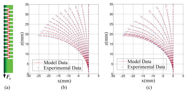
The experimental shapes with tendon force from 1N to 13N in 2N increments for the bending and unbending cycles were used to determine the best friction coefficient of 0.66. Then the experimental shapes with tendon force from 0N to 12N in 2N increments were used to test the model. Shape comparison for the calibration and test are shown in Fig. 7. The total mean error was 0.61±0.43mm. We observed that during the bending phase, the DCM shape changed gradually with the gap between the shapes increasing uniformly. During the unbending phase, the gap between shapes did not decrease uniformly. From Fig. 7, the shape at 13N is not a typical circle with constatnt curvature. This agrees with the analysis of Murphy et al. [20].
Fig. 7.
Shape comparison between the model data and experimental data with free bending and unbending phases: (a) shows the applied force; (b) shows the comparison with free bending phase; (c) shows the comparison with unbending phase.
D. Tendon Force Distribution Along the Channel
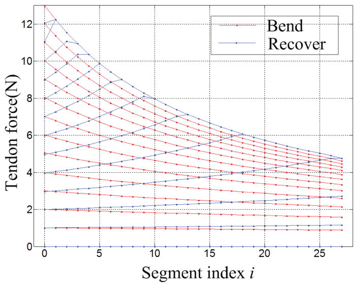
The shape of the DCM during the free bending and unbending cycles is different (Fig. 7). This might be due to the friction force affecting the tendon distribution and leading to the different deformation for each joint during the bending/unbending cycle. Simulation results for tendon force distribution Fi(i =0–27) (defined in Section IV-F) along the 27 segments from the proximal to the distal end of the DCM during the bending/unbending cycle suggest tendon force profiles are significantly different when comparing loading (DCM bending) and unloading (DCM recovery) cycles (Fig. 8). During the loading cycle, the force profile from the proximal to distal segment simultaneously increases along all segments. However, during the unloading cycle, the tendon force reduces incrementally (one segment at a time) from the proximal to the distal segment. When the maximum force 13N is applied to the tendon in the proximal end, the force in the proximal end is more than twice the force in the distal end.
Fig. 8.
Display of tendon force distribution along the channel when DCM is bent and unbent
E. Experiments with the External Tip Force and External Force on the DCM Body
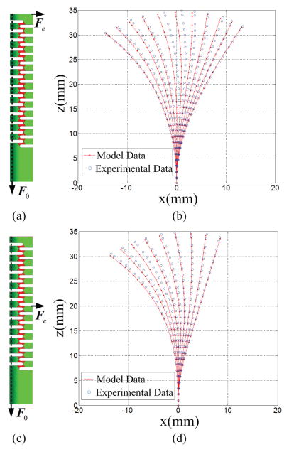
We performed the experiments incorporating an external force. The weight, 50g, was hung from the tip of the DCM (Fig. 9(a)). The tendon was pulled from 0N to 10N five times in 1N increments. Results are shown in Fig. 9(b). The total mean error was 0.75±0.42mm. The weight, 100g, was hung from the 7-th flexible link (Fig. 9(c)); the weight application was at the point qE15, which can be transformed to the neutral axis of flexible link at Point Q defined in Fig. 3(b). Since the force was applied to the beam body, Eq. 5 was considered to reflect this additional force. In the experiment, the tendon force varied from 0N to 8N in 1N increments five times (Fig. 9(d)). The total mean error was 0.83±0.44mm.
Fig. 9.
Shape comparison between the model data and experimental data with the external tip force: (a) & (c) show the applied force; (b) & (d) show the shape comparison.
VI. Discussion
A. Sources of Error
Results in Section V show that the proposed model can predict the shape of the DCM with high accuracy. The model was relatively accurate for all three scenarios discussed in Section V. The following describes some of the main sources of error:
The friction model utilizing Coulomb friction assumes that the coefficient of static friction equals that of kinetic friction μc; this has shown good accuracy when predicting the deformation, but is still not accurate enough to describe the real situation. Advanced friction models, such as the Dahl or LuGre models [21], show the potential to describe the friction more accurately.
The assumption that the friction coefficient between the sharp corner and cable is the same at each contact point is not appropriate due to possible inconsistent contact conditions resulting in different μc at contact points. Ideally, friction would be reduced as much as possible using a PTFE-coated cable or potential ultrasonic vibration technology [22].
The wider discrepancy between model and experimental data in some cases when the DCM is subject to a tip force (Fig. 9(b)) may result from the tendon-channel gap. This gap changes the contact conditions and relative angles, β2i+1 and β2i+2 (Fig. 5(b)), between the tendon and the rigid link, especially in the almost straight configuration. This, in turn, impacts the propagation of tendon force from the tip to the base, therefore leading to the inaccurate deformation of the entire DCM. One potential solution is to use a larger diameter cable decreasing the tendon-channel gap; however, such a cable must remain flexible enough to bend with the DCM.
B. Variation of Notches
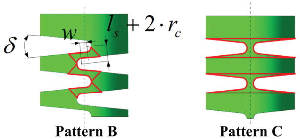
The partition approach and mechanical model in this paper are also suitable for other compliant joints such as pattern B & C shown in Fig. 10. Pattern B is with more general compliant joints created by the adjacent crossed and angular notches; while Pattern C is the one transformed from Pattern B by moving the left notches to the left of centerline and the right notches to the upper right when decreasing w and ls. Both of the patterns can also be analyzed by the partition method and mechanical model proposed in Section III–IV. The partitioned rigid and flexible links are shown in Fig. 10. In addition, the calibration approach in Section V can also be adopted to derive the equivalent Young’s modulus and friction coefficient.
Fig. 10.
Variation of notches: Pattern B shows the DCM cut off by the cross angular notch; Pattern C shows the DCM cut off by the uncrossed and symmetrical V-shaped notch.
VII. Conclusion
The paper proposed an effective partition approach and derived a mechanical model of any tendon driven notched DCM with compliant joints. This model predicted the deformation of the DCM in the presence of the tendon force, external tip force, and the body force and/or combinations therein. It also shows the potential to describe the DCM with varying notches.
The comparison of experiments and simulations showed that the model can predict the shape of the DCM accurately during free bending/unbending and loaded bending/unbending cycles. Results indicated that the mean tip error of all the experiments was 0.62±0.41mm, about 1.77±1.17% of the total manipulator length. The model and its simulation results enabled an explanation of the hysteresis. The effect of varying friction coefficients was also discussed and evaluated.
The model developed in this paper can be used to design or optimize the DCM and/or associated similar tools. It can be used for model-based external force prediction based on intrinsic force sensing technology and control of the DCM with compliant joints. Also, the effects from the friction force can also be compensated for in the control algorithm.
Fig. 6.
Experimental Setup: DCM, CMOS camera, linear sliding stage was fixed to the optical table to avoid the vibration; the tendon was fixed to the force sensor and then actuated gradually to keep the quasi-static scenario.
Acknowledgments
This work was supported by NIH/NIBIB grant R01EB016703. The work of A. Gao was supported in part by National Natural Science Foundation of China under Grant 61473281 and in part by China Scholarship Council under Grant 201408210100.
Biographies

Anzhu Gao received the B.S., M.S. degrees in mechatronics engineering from Harbin Institute of Technology in China, in 2009, 2011, respectively. He worked as an engineer from 2011 to 2013. He is currently a Ph.D. student at the Shenyang Institute of Automation, State Key Laboratory of Robotics, Chinese Academy of Sciences, and also University of Chinese Academy of Science. He worked as a visiting student with the Laboratory for Computational Sensing and Robotics from 2014~2015. His research interests include medical robots, continuum robots.
Ryan J. Murphy received the Ph.D. degree in mechanical engineering from Johns Hopkins University, in 2015. He is currently with the Biomechanical- and Image-Guided Surgical Systems Laboratory, part of the Laboratory for Computational Sensing and Robotics. He is also a Senior Professional Staff Member with the Johns Hopkins University Applied Physics Laboratory, Laurel, MD. His research interests include medical robots, robot and computer-assisted surgery, robot kinematics and dynamics, systems and software engineering, and biomechanics.

Hao Liu received the B.S., M.S., and Ph.D. degrees in mechanical engineering from the Harbin Institute of Technology in China, in 2004, 2006, and 2010, respectively. He is currently an Associate Professor with the Shenyang Institute of Automation, Chinese Academy of Sciences. His research interests include surgical robots, medical sensors, surgical navigation, and robot control.

Iulian Iordachita (M’08–SM’14) received the B.Eng. degree in mechanical engineering, the M.Eng. degree in industrial robotics, and the Ph.D. degree in mechanical engineering from the University of Craiova, Romania, in 1984, 1989, and 1996, respectively. He is currently a Research Faculty Member with the Mechanical Engineering Department, Whiting School of Engineering, Johns Hopkins University, a Faculty Member with the Laboratory for Computational Sensing and Robotics, and the Director of the Advanced Medical Instrumentation and Robotics Research Laboratory. His current research interests include medical robotics, image guided surgery, robotics, smart surgical tools, and medical instrumentation.

Mehran Armand received the Ph.D. degree in mechanical engineering and the Ph.D. degree in kinesiology from the University of Waterloo, ON, Canada, with a focus on bipedal locomotion. He is currently a Principal Scientist and holds joint appointments with Mechanical Engineering and Orthopaedic Surgery. Prior to joining JHU/APL in 2000, he completed postdoctoral fellowships at JHU Orthopaedic Surgery and Otolaryngology-head and neck surgery. He currently directs the collaborative Laboratory for Biomechanical and Image-Guided Surgical Systems, Laboratory for Computational Sensing and Robotics, JHU/Whiting School of Engineering.
Footnotes
Color versions of one or more of the figures in this paper are available online at http://ieeexplore.ieee.org.
Contributor Information
Anzhu Gao, State key Laboratory of Robotics, Shenyang Institute of Automation, Chinese Academy of Sciences, Shenyang, China; A. Gao is also with University of Chinese Academy of Sciences, Beijing, China.
Ryan J. Murphy, Johns Hopkins University Applied Physics Laboratory, Laurel, MD 20723-6099, USA.
Hao Liu, State key Laboratory of Robotics, Shenyang Institute of Automation, Chinese Academy of Sciences, Shenyang, China; A. Gao is also with University of Chinese Academy of Sciences, Beijing, China.
Iulian I. Iordachita, Laboratory for Computational Sensing and Robotics (LCSR), Johns Hopkins University, Baltimore, MD 21218, USA.
Mehran Armand, Laboratory for Computational Sensing and Robotics (LCSR), Johns Hopkins University, Baltimore, MD 21218, USA. Johns Hopkins University Applied Physics Laboratory, Laurel, MD 20723-6099, USA.
References
- 1.Luketich JD, Pennathur A, Awais O, Levy RM, Keeley S, Shende M, Christie NA, Weksler B, Landreneau RJ, Abbas G, Schuchert MJ, Nason KS. Outcomes after minimally invasive esophagectomy: review of over 1000 patients. Annals of surgery. 2014 Jul;256(1):95–103. doi: 10.1097/SLA.0b013e3182590603. [DOI] [PMC free article] [PubMed] [Google Scholar]
- 2.Kutzer MD, Segreti SM, Brown CY, Taylor RH, Mears SC, Armand M. Design of a new cable-driven manipulator with a large open lumen: Preliminary applications in the minimally-invasive removal of osteolysis. Proc. IEEE Int. Conf. Robot. Autom; Shanghai, China. 2011; pp. 2913–2920. [Google Scholar]
- 3.Engh CA, Egawa H, Beykirch SE, Hopper RH, Charles A. The quality of osteolysis grafting with cementless acetabular component retention. Clinical orthopaedics and related research. 465:150–154. doi: 10.1097/BLO.0b013e3181576097. [DOI] [PubMed] [Google Scholar]
- 4.Gao A, Carey JP, Murphy RJ, Iordachita I, Taylor RH, Armand M. Progress toward robotic surgery of the lateral skull base surgery: integration of a dexterous continuum manipulator and flexible ring curette. Proc. IEEE Int. Conf. Robot. Autom; Stockholm, Sweden. 2016; pp. 4429–4435. [Google Scholar]
- 5.Murphy RJ, Kutzer MDM, Segreti SM, Lucas BC, Armand M. Design and kinematic characterization of a surgical manipulator with a focus on treating osteolysis. Robotica. 2014;32(6):835–850. [Google Scholar]
- 6.Moses MS, Murphy RJ, Kutzer MD, Armand M. Modeling cable and guide channel interaction in a high-strength cable-driven continuum manipulator. IEEE/ASME Trans Mechatron. 2015 Dec;20(6):2876–2889. doi: 10.1109/TMECH.2015.2396894. [DOI] [PMC free article] [PubMed] [Google Scholar]
- 7.Liu H, Farvardin A, Grupp R, Murphy RJ, Taylor RH, Iordachita I, Armand M. Shape tracking of a dexterous continuum manipulator utilizing two large deflection shape sensors. IEEE Sensors Journal. 2015 Oct;15(10) doi: 10.1109/JSEN.2015.2442266. [DOI] [PMC free article] [PubMed] [Google Scholar]
- 8.Xu K, Simaan N. An investigation of the intrinsic force sensing capabilities of continuum robots. IEEE Trans Robot. 2008 Jun;24(3):576–587. [Google Scholar]
- 9.Simaan N, Xu K, Wei W, Kapoor A, Kazanzides P, Taylor RH, Flint P. Design and integration of a telerobotic system for minimally invasive surgery of the throat. Int J Robot Res. 2009 May;28(9):1134–1153. doi: 10.1177/0278364908104278. [DOI] [PMC free article] [PubMed] [Google Scholar]
- 10.Jones BA, Gray RL, Turlapati K. Three dimensional statics for continuum robotics. Proc. IEEE/RSJ Int. Conf. Intell. Robots Syst; St. Louis, MO, USA. 2009; pp. 2659–2664. [Google Scholar]
- 11.Rucker DC, Webster RJ. Statics and dynamics of continuum robots with general tendon routing and external loading. IEEE Trans Robot. 2011 Dec;27(6):1033–1044. [Google Scholar]
- 12.Camarillo DB, Miline CF, Carlson CR, Zinn MR, Salisbury JK. Mechanics modeling of tendon-driven continuum manipulators. IEEE Trans Robot. 2008 Dec;24(6):1262–1273. [Google Scholar]
- 13.Giorelli M, Renda F, Calisti M, Arienti A, Ferri G, Laschi C. A two dimensional inverse kinetics model of a cable driven manipulator inspired by the octopus arm. Proc. IEEE Int. Conf. Robot. Autom; Saint Paul, MN, USA. 2012; pp. 3819–3824. [Google Scholar]
- 14.Kato T, Okumura I, Song S, Golby AJ, Hata N. Tendon-driven continuum robot for endoscopic surgery: preclinical development and validation of a tension propagation model. IEEE/ASME Trans Mechatron. 2015 Oct;20(5) doi: 10.1109/TMECH.2014.2372635. [DOI] [PMC free article] [PubMed] [Google Scholar]
- 15.Du Z, Yang W, Dong W. Kinematics modeling of a notched continuum manipulator. J Mech Robot. 2015 Nov;7(4):041047. [Google Scholar]
- 16.York PA, Swaney PJ, Gilbert HB, Webster RJ. A wrist for needle-sized surgical robots. Proc. IEEE Int. Conf. Robot. Autom; Seattle, WA, USA. 2013; pp. 1776–1781. [DOI] [PMC free article] [PubMed] [Google Scholar]
- 17.Murphy RJ, Moses MS, Kutzer MD, Chirikjian GS, Armand M. Constrained workspace generation for snake-like manipulators with applications to minimally invasive surgery. Proc. IEEE Int. Conf. Robot. Autom; Karlsruhe, Germany. 2013; pp. 5341–5347. [Google Scholar]
- 18.Subramani G, Zinn MR. Tackling friction-an analytical modeling approach to understanding friction in single tendon driven continuum manipulators. Proc. IEEE Int. Conf. Robot. Autom; Seattle, WA, USA. 2015; pp. 610–617. [Google Scholar]
- 19.Otake Y, Murphy RJ, Kutzer MD, Taylor RH, Armand M. Piecewise-rigid 2D–3D registration for pose estimation of snake-like manipulator using an intraoperative x-ray projection. SPIE Medical Imaging International Society for Optics and Photonics; San Diego, California, USA. 2014; pp. 90360Q–90360Q. [Google Scholar]
- 20.Murphy RJ, Otake Y, Taylor RH, Armand M. Predicting kinematic configuration from string length for a snake-like manipulator not exhibiting constant curvature bending. Proc. IEEE/RSJ Int. Conf. Intell. Robots Syst; Chicago, IL, USA. 2014; pp. 3515–3521. [Google Scholar]
- 21.Geffen V. A study of friction models and friction compensation. Technische Universiteit Eindhoven; The Netherlands: pp. 1–24. [Google Scholar]
- 22.Kumar VC, Hutchings IM. Reduction of the sliding friction of metals by the application of longitudinal or transverse ultrasonic vibration. Tribol Int. 2015;37(10):833–840. [Google Scholar]


