Abstract
Active magnetic resonance (MR) tracking for gynecologic brachytherapy was made possible by attaching the micro radiofrequency coils to the brachytherapy applicator. The rectangular planar micro coil was fabricated using flexible printed circuits with dimensions of 8mm×1.5mm. A 5-Fr (1.6mm) tungsten brachytherapy stylet was custom-machined to incorporate the micro coils. The finite element analysis and the phantom tissue studies show that the proposed device enables in situ, real-time guidance of access routes to the target anatomy safely and accurately. The setup was tested in a Siemens 3T MR scanner. The micro coils can be localized rapidly (up to 40 Hz) and precisely (resolution: 0.6×0.6×0.6mm3) using an MR-tracking sequence.
Index Terms: Magnetic Resonance Imaging (MRI), active tracking, stylet, brachytherapy
I. Introduction
Gynecological cancer is one of the most commonly diagnosed female cancers, causing about 30,000 deaths alone in the United States in 2015 [1]. Depending on the type of gynecologic cancer, radiation, surgery and/or chemotherapy [2] are the typical treatments recommended based upon the age of the patient, the cancer stage and the grade at diagnosis. Focussed radiation with brachytherapy treats cancer effectively by placing radioactive sources into or close to the tumor, allowing a high radiation dose to be administered to the tumor while sparing the surrounding healthy tissues. This procedure requires improved navigational accuracy and efficiency, which may be accomplished by intra-operative imaging combined with specially designed instruments for brachytherapy.
Imaging modalities such as computer tomography (CT) and ultrasound are often used for planning and navigation during brachytherapy [3]. Regardless of the difficulty in handling the image plane within the anatomical region of interest, the primary disadvantage of CT and ultrasound are their inability to distinguish tumors from surrounding healthy tissues [4] such as the bowel, and to determine the accurate size and location of the tumor. Thus, MRI-guided brachytherapy holds great potential in cervical cancer treatment [5].
In CT- or ultrasound-guided brachytherapy, 3D- electro-magnetic (EM) position sensors are integrated with the brachytherapy applicator to intra-operatively track its location relative to the anatomy of interest [6]. However, in an MRI-guided intervention, the strong magnetic field and metallic-lined bore preclude the use of sensors made of ferromagnetic materials, or EM sensors that employ magnetic field. Two major approaches have been presented in literature to track a brachytherapy applicator’s position under MRI: i) Passive tracking: the device is visualized in MR images by utilizing its susceptibility artifact or attached fiducial markers made of gadolinium [7] or dysprosium [8], which not only requires generous portions of scanning time to deduce the position in the MR images [9], but also inducse delays and causes inconsistent guidance for surgical manipulation; ii) Active tracking: the pose (position and orientation) of the surgical device can be detected in a high update rate scanning sequence. Previously reported active tracking approaches include optical tracking [10, 11], gradient field sensing [12] and micro RF coils [13-15]. The optical tracking approach uses optical markers attached to an instrument to register the instrument to the MR coordinate system. The real time end effector pose can be obtained through the homogeneous transformation from the optical tracker coordinates to MR coordinates. Hata et al. employed an optical tracker (Flash Point, Image-Guided Technologies, Boulder, CO) on the holder of the needle for MRI guided liver ablation [11]. One of the main disadvantages with optical tracking is that the end effector pose is numerically calculated based on the pose of optical marker, which can introduce errors such as inaccurate coordinate frame registration. Gradient field approach sensing (EndoScout, RobinMedical Systems, Baltimore, MD) uses 3 orthogonal pick up coils to calibrate the gradient fields of the MR scanner. The pose of the end effector can be calculated from the gradient strength based on the linear relationship between the gradient field and coordinates in the MR scanner. However, it is challenging to track the metallic device with this approach due to the tendency of a metallic object to distort the homogeneity of magnetic and electric fields. As the linearity of these fields is relied upon for determining the object’s poses, error is likely to be introduced. A promising method to track the metallic stylet with high resolution is the micro RF coil. The small radio-frequency (“micro tracking”) coils can be integrated with the interventional device and can receive conspicuous MR signals for robust and faster 3D localization at high resolution (0.2 mm and 0.3°) [16, 17]. Multiple tracking coils could be mounted into particular segments of the device to measure the pose of the surgical device end effector.
In this paper, we propose a customized brachytherapy stylet with integral micro tracking coils. The working principle of active tracking coils under MRI is also presented. Detailed experimental evaluation of the customized stylet was conducted to ensure precise and safe navigation under various insertion conditions, posing a high potential for clinical testing and use in gynecologic brachytherapy guided by intraoperative MR images.
II. Methods
A. Brachytherapy System Setup
Fig. 1 shows the standard device for needle placement in interstitial gynecologic brachytherapy. The placement starts with insertion of a vaginal obturator into the patient against the vaginal apex. The Syed-Neblett template (Best Medical International Inc., Springfield, VA, USA), which fits over the obturator, is sutured to the patient’s perineal skin at its four corners. The template is made of plastic and contains a grid of 5-mm holes, through which multiple interstitial needles can be inserted into the treatment region. The interstitial needle is a hollow plastic tube with a sealed sharp tip (ProGuide Needles, Nucletron Co., Veenendaal, Netherlands). An MR compatible stylet made of a tungsten alloy is placed inside the interstitial needle to provide sufficient mechanical strength during the insertion. After the proper placement of the needles, the active tracking stylets are withdrawn, and radioactive sources can be pushed into the hollow needles by a computer-controlled machine. The stylet is covered by the interstitial plastic tube (the catheter) during the brachytherapy procedure. Note that both the customized stylet and the micro-tracking coils will not make contact with human tissue, which significantly reduces risk. In addition, the styles can be sterilized using Ethylene Oxide (ETO) sterilization, and used multiple times.
Fig. 1.
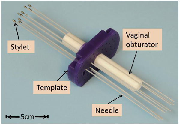
Applicators for MR-guided gynecologic brachytherapy. The dimensions of the template are 10.7×7 (L×W) cm2 with thickness of 1.5cm; the obturator is: 15-cm long with diameter of Ø2.2cm.
B. Stylet fabrication
Multiple micro-coils are mounted along the stylet with medical device adhesive (Henkel, Dusseldorf, Germany), in order to achieve active MR tracking of the distal needle shaft. Two or three grooves (10-mm long and 0.45-mm deep) for integrating microcoils and a thin slot for channeling micro-coaxial cable were carved onto the surface of the stylet (Fig. 2). The micro-coaxial cables (Ø0.13mm) were routed inside the slot along the stylet’s shaft in order to connect the microcoils with the MR receiver system. Note that the tungsten alloys were classified as hard brittle materials; therefore a 4-mm chamfer was used instead of a sharp edge at both ends of each groove to reduce the risk of stylet breakage at the machined slots.
Fig. 2.
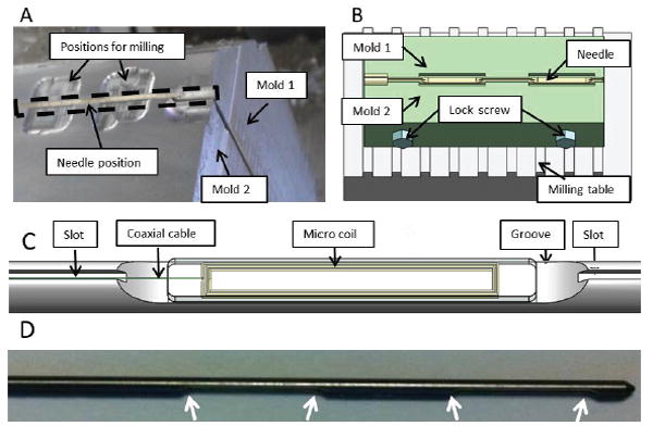
(A) Setup of the clamping mechanism for the fabrication of the groves in the tungsten stylet; (B) Schematic diagram of the clamping mechanism on the milling table; (C) Detailed view of the coil integrated on the groove of the stylet; (D) The white arrows denoted 4 chamfer on the fabricated stylet in the curve of 4-mm radius.
The main challenge in fabricating the tungsten stylet was to ensure fabrication accuracy and maintain mechanical strength of the stylet. A customized design of the clamp was used to mount the stylet firmly during the machining process (Fig. 2a-b). The clamp, consisting of two half-stylet molds made of aluminum, can be fixed onto a milling machine. The two molds were 400 mm long and can hold the full-length stylet during fabrication. Once the stylet was clamped, a two-fold machining process proceeded: 1) Two 10-mm grooves with a separation of 10 mm were milled using the Carbide End Mill (MTS-401-08, RobbJack, CA, USA); 2) a long slot with a 200×300 μm2 cross section was cut along the entire stylet shaft using a carbide saw (C12-008-16-36, RobbJack, CA, USA).
C. Micro coil design
The standard RLC electrical circuit forms the basis of the micro tracking coil. Its circuit system consists of a resistive load (R) which consumes energy, inducing a damping effect during the resonance. In practice, the resistive load mainly results from capacitive coupling into the liquid surrounding the coil, as well as inductive coupling to the metal in thestylet. The energy stored in the capacitor and inductor, both of which determine the resonance frequency of the circuit. Referring to [18], the resonance frequency of the system can be written as:
| (1) |
where L and C are the inductance and capacitance of the circuit respectively. From Eq. (1) alone, there are infinite combinations of the L and C to generate a specific resonance value. However, it is worth noting that the quality factor, acting as another important consideration of designing the RLC circuit, which can be written as
| (2) |
The larger Q value, the more magnetic energy can be stored in the micro coil. Therefore, a trade-off between L and C needs to be made in the tuning-matching of the coil.
The microcoil was fabricated from 8 loops of copper electrical loop wires in this study. To minimize the dimension of the microcoil (8mm × 1.5mm), copper tracks were printed on the two layers of flexible printed circuit (FPC) sheet, forming the microcoil (Fig. 3a). Each layer contains a rectangular loop on both sides, and the two layers are connected in series via a plated-through hole in order to form a coil with four loops. The coil was connected to a tuning-matching circuit (Fig.3b) sealed in a box at the proximal end of the stylet through a micro-coaxial cable. The circuit was tuned to 123.183MHz, equivalent to the 3T Larmor frequency, and also matched with 50 ohm specific impedance of the microcoaxial cable (Fig. 3c).
Fig. 3.
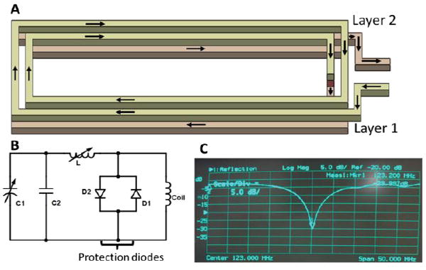
(A). Schematic diagram showing the two layers of rectangular RF coil. The arrows indicate the flow of current in the coil; (B). circuit diagram of the tuning and matching circuit; (C). The resonance frequency of the micro coil is found at 123.183MHz (the Siemens 3T MRI Larmor frequency)
D. Real-time active MR tracking
A dedicated MR tracking sequence was developed to acquire three orthogonal projections of the micro-coils along x, y and z directions [19]. The tracking sequence can achieve a 3D spatial resolution of up to 0.6 × 0.6 × 0.6 mm3 and a sampling rate of up to 40 Hz. The tracking sequence can also be used in concert with intra-procedural MR imaging, in which tracking is temporally interleaved with real-time imaging, thus enabling rapid acquisition of images at the instantaneous needle location. The micro-coils are connected to a custom-built receiver interface which has a conventional coil plug for the Siemens MR system, and can be used concurrently with other imaging coils. The receiver interface has eight channels, allowing simultaneous tracking of up to eight microcoils. Each channel includes a frequency-tuned RF pre-amplifier. An RF-shielded electrical isolation box was connected between the active stylet and the receiver, limiting the 60 Hz leakage currents to less than 10 μA in each of the eight channels (Fig. 4).
Fig. 4.
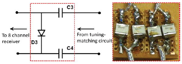
Left: circuit diagram of the connection between the micro-tracking coil and the coil receiver plugin to the MRI scanner [19]. Right: the capacitors (0.1 μF) provide protection against DC currents reaching the patient with >1k-voltage breakdown. The diode is used to senable the MRI receiver to properly recognize the attached micro coil.
III. Results and Discussion
A. Stylet Finite Element Analysis for Surgical Safety
The stylet bears complex reaction forces of the surrounding tissues during the percutaneous therapy [20]. Therefore, it is important to verify the fabricated stylet’s mechanical response to a possible range of applied insertion forces during the procedure, thus ensuring that it has the mechanical strength to push through human tissue.
The stylet insertion process can be divided into four sequential phases: i) tissue deformation, ii) steady-state penetration, iii) relaxation and iv) extraction phase [21]. The insertion force continually rises and reaches its peak value at the end of steady-state penetration. According to [22], the force applied at the tip along the insertion axis is the largest force component, of which 10N is sufficiently large to penetrate uterine tissue. Insertion accomplished by a minimal amount of force demonstrates a delicate control of the stylet with respect to several factors, such as the location of target anatomy, insertion depth and speed, as well as the variation of force. Finite element analysis (FEA) was conducted to verify and compare the stylet before and after fabrication. Maximum stress and displacement were recorded continuously under operational conditions at various forces ranging from 1N to 10N, at a step of 1N.
The maximum stress and displacement depended linearly on the applied force (Fig. 5). The peak stress occurred at the edge of the groove with the maximum value of 17.6 MPa when the insertion force was 10N, which was much smaller than the yield strength (750 MPa). The maximum displacement was approximately 0.18 mm as measured at the proximal end, regardless of the MR tracking resolution, which was minimal with respect to the dimensions of the stylet. These results demonstrate that the fabricated stylet retains sufficient mechanical strength for brachytherapy procedures.
Fig. 5.
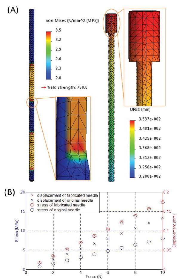
(A) Case study of the stylet maximum stress (left) and displacement (right) at an applied insertion force of 2N; (B) Stress and displacement with respect to insertion forces ranging from 1N to 10N.
B. Stylet deflection analysis
Shape deflection of the fabricated stylet during stylet placement in brachytherapy is another evaluation index since it significantly affects the procedure’s safety and accuracy. To simulate the needle insertion procedure, the needle/stylet combination, mounted on a lead screw (SLW 1040, IGUS®), was driven into a tissue equivalent phantom (CIRS, VA, USA) by a DC motor (RC-260SA-2295, Mabuchi Motor) coupled with a 400:1 planetary gearbox to reduce the insertion speed The detailed setup can be seen in Fig. 6. We chose the tissue equivalent phantom to mimic the brachytherapy study so as to guarantee the accuracy and comparability of each trial. Two 5 degrees-of-freedom (DoF) electromagnetic (EM) tracking sensors (Aurora NDI, Ontario, Canada) were mounted on the stylet to detect its deflection throughout the insertion procedure. The sensors were mounted on the two grooves on the stylet and coverd by a catheter during insertion procedure. The shape deflection was defined as the absolute value of the orientation angle difference between the two EM sensors during the period from needle penetration to the end of insertion. The angle differences under various test conditions are depicted in Fig. 7, which shows that the angle differences of stylet before and after fabrication reflect a similar pattern with regard to the insertion speed. Lower speed leads to minimal deflection. The minimum anglulare difference was approximately 0.4° and the maximum angular difference was around 2°. The distance between the two EM sensors mounted on the associated grooves of the active stylet is 20mm. Therefore, the deflection of stylet is around 0.35 mm (20mm*pi/180=0.35mm). These imply neglectable bending of the stylet insertion during brachytherapy, thus guaranteeing procedural safety and accuracy.
Fig. 6.
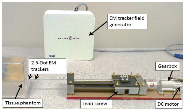
Experimental setup of the needle insertion test. Two EM trackers with a separation of 20mm were mounted on the grooves of the active stylet.
Fig. 7.
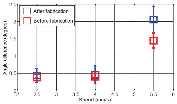
Mean value of the angle difference with respect to the insertion speed and stylet condition (before and after fabrication). Each trial was repeated five times.
C. Active MR tracking test
The active MR tracking test was performed in a 3T Siemens Verio scanner. The zero-phase-reference and Hadamard multiplexing schemes were applied to correct the inhomogeneities of the static magnetic field B0 [14]. To eliminate the effect of RF field (B1) inhomogeneities caused by the tungsten stylet, the phase-field dithering (PFD) was integrated into the tracking sequence. The tracking setup is able to achieve a resolution of 0.6×0.6×0.6 mm3 at 40 Hz (Table 1). It is worth noting that a variety of imaging sequences were applied with the maximally allowable Specific Absorption Rate (SAR) of 4W/kg in order to quantify the potential heating effect at the active tracking coils. The active stylet was placed into a cylindrical plastic bottle filled with a liter of tissue-mimicking gel (2% agar, 0.9% NaCl, 97.1% water) and the maximum recorded temperature rise is approximately 0.11 °C.
TABLE I.
MR parameters used for active tracking test
| Parameters | Tracking | Imaging |
|---|---|---|
| Repetition/Echo/Inversion time (ms) | TR/TE=19.75/3 | TR/TE/TI = 1200/1.55/900 |
|
| ||
| Flip angle α | 5° | 75° |
|
| ||
| Physical resolution (mm3) | 0.6×0.6×0.6 | 0.5×0.5×1 |
|
| ||
| Slice thickness | - | 5 mm |
| Field of View (FOV) | - | 162×199 mm2 |
To test the tracking accuracy, the active needle was then fixed inside a water phantom and active tracking measurements were performed with phantom placed at 10 different locations inside the MR scanner. Note that the susceptibility difference between metal and tissue is greater than that between air and tissue. As can be seen in Fig. 8, a larger susceptibility artifact is observed when the metallic stylet is placed within the plastic catheter. The increased image artifact can degrade the precision of the passive 3-D localization, since the perceived diameter is larger than the true diameter of the object.
Fig. 8.
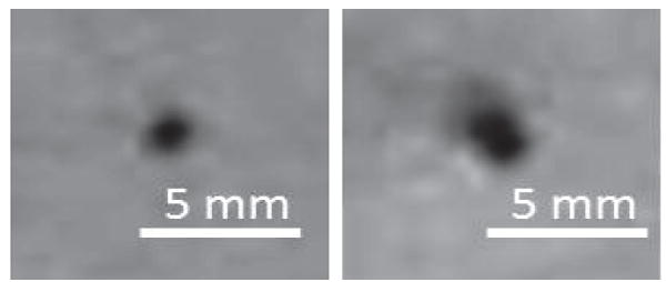
MR images of a gel phantom model inserted with a catheter, showing the difference in artifact size between the catheter withour (Left) and with a stylet put inside (Right). The hole size is doubled.
The ground truth of the needle positions were measured using high-resolution 3D MR images acquired with a inversion-recovery gradient echo (MP-RAGE) sequence (detailed parameters in Table 1). 100 tracking measurements were performed at each location and the active device was capable of providing accurate (0.5 mm) localization (Fig. 9a-b). In the dynamic tracking experiment, eight needles were inserted into the phantom with conventional stylets. The needles appear as signal voids in the MR images because of the susceptibility artifacts created by the metallic stylet. The trajectory of each needle was reconstructed by replacing the conventional stylet with the active stylet and continuously tracking the tip position of the stylet during its insertion (Fig. 9c), allowing accurate catheter trajectory reconstruction for treatment planning.
Fig. 9.
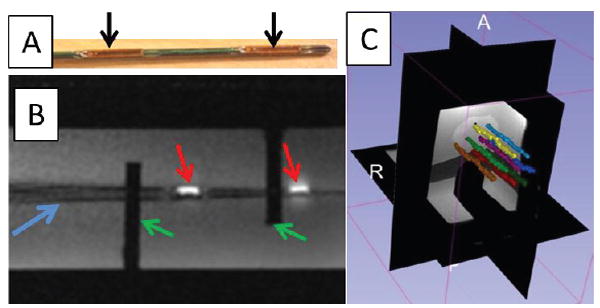
(a) Actively tracked stylet. Black arrows denote the micro-tracking coils; (b) MR image of the active tracking stylet within the custom-machined container acquired by two-dimensional gradient echo (2D-GRE). Red arrows denote the MR image of the micro tracking coils. Blue arrow denotes the image of the stylet. Green arrows denote the fixed structure of the container. (c) Screen shot of the 3D Slicer display during navigation. Eight needle trajectories were reconstructed during the stylet insertion/removal.
IV. Conclusion
In our previous paper [19], we focused the discussion on the active tracking technique, phantom tests and human trial results. In this paper, we describe the engineering aspects, including stylet fabrication, FEM study, stylet deflection evaluation, MR compatibility and MR safety. Those issues are the practical aspects of the development of an MR-tracked metallic stylet, and they are particularly important for the safe implementation of this device in a clinical environment. These results will serve as a benchmark and reference for the future development of the MR active tracking stylet.
This paper mainly presents the design, fabrication and evaluation of an active metallic stylet for gynecologic brachytherapy. It can actively track a needle with up to 0.6×0.6×0.6 mm3 resolution at high update rate of 40Hz. Our FEA and phantom studies have shown the technical feasibility that allows for safe and precise stylet insertion under various conditions. The proposed stylet can withstand large insertion forces of 10 N, such that the maximum stress is simulated at 17.6 MPa on the stylet groove, which is still far less than the yield strength (750 MPa) of tungsten material. Only approximately 0.4 degree of deflection was measured as the stylet was inserted into the gel phantom at an insertion speed of 2.5 mm/s.
It is worth noting that the active coils have no adverse effect on the quality of MR images. The active coils are connected to independent receiving channels and can be turned on/off during scanning. When the coils are turned on, they produce a bright spot at the coil location in the MR image (Fig. 9b). When the coils are turned off, they do not affect image quality due to their compact size. Unlike the previously described wireless RF coil [23, 24], which inductively couples the micro RF coil with the MR receiver coil and affects the image quality when the coil is in the FOV, the presented active coils could provide high resolution tracking without affecting the image quality.
Although the respiratory motion and tissue deformation effects have yet been considered in current study, our previous results [25] show that the such physiological motion could be corrected by using at tetrahedron with 4 tracking coils. In brachytherapy or biopsy, soft-tissue deformation is common, which is varied by different conditions, i.e. tissue characteristics, stylet insertion force and patient motion. MR active tracking stylet allows the real-time monitoring of the stylet tip position. This provides an approach to keep tracking the proximity [26] of the surgical instrument relative to target anatomy so as to minimize the positional error of needle insertion caused by tissue deformation. The effect of tissue deformation will be further studied in our future work. In addition, we will also focus on the integration of the active tracking and real-time MRI in the future, closing the control loop of various surgical manipulations, even those assisted by MR-conditional robots or actuators [27, 28].
Acknowledgments
This material is based upon work supported by the American Heart Association 10SDG261039, NIH R21 167800, University of Georgia (UGA)-Georgia Regent University Seed Grant, American Society for Quality Dr. Richard J. Schlesinger Grant, The Croucher Foundation, and Research Grants Council, Hong Kong. We gratefully acknowledge Lewis Fortner in Instrument Design & Fabrication Shop at UGA, and Terrance Walsh in the Machine Shop at the UGA College of Engineering for their advices in tungsten fabrication. Wei Wang would like to thank for BWH Department of Radiation Oncology post-doctoral fellowship support.
Contributor Information
Yue Chen, College of Engineering, The University of Georgia, Athens, GA, 30605 USA, and is also with Department of Mechanical Engineering, The University of Hong Kong, HK, China (ychen@uga.edu, ychen14@hku.hk).
Wei Wang, Department of Radiology, Brigham & Women’s Hospital, Boston, MA, 02115 USA, and is also with the Department of Radiation Oncology, Brigham & Women’s Hospital, Boston, MA, 02115 USA (WWANG21@PARTNERS.ORG).
Ehud J. Schmidt, Department of Radiology, Brigham & Women’s Hospital, Boston, MA, 02115 USA (ESCHMIDT3@PARTNERS.ORG)
Ka-Wai Kwok, Department of Mechanical Engineering, The University of Hong Kong, HK, China (kwokkw@hku.hk).
Akila N. Viswanathan, Department of Radiation Oncology, Brigham & Women’s Hospital, Boston, MA, 02115 (aviswanathan@partners.org)
Robert Cormack, Department of Radiation Oncology, Brigham & Women’s Hospital, Boston, MA, 02115 (rcormack@lroc.harvard.edu).
Zion Tsz Ho Tse, College of Engineering, The University of Georgia, Athens, GA, 30605 USA (ziontse@uga.edu).
References
- 1.American Cancer Society Inc.; 250 Williams Street, NW, Atlanta, GA A 30303-1002: [April 2, 2015]. Cancer facts and figures 2015. www.cancer.org/acs/groups/content. [Google Scholar]
- 2.Halperin EC, Brady LW, Wazer DE, Perez CA. Perez & Brady’s Principles and Practice of Radiation Oncology. Lippincott Williams & Wilkins; 2013. [Google Scholar]
- 3.Gerbaulet A, Gerbaulet A. The GEC ESTRO handbook of brachytherapy. Estro Brussels; 2002. [Google Scholar]
- 4.Viswanathan AN, Erickson BE, Potter R, Kirisits C. Gynecologic Radiation Therapy. Springer; 2011. [Google Scholar]
- 5.Viswanathan AN, Szymonifka J, Tempany-Afdhal CM, O’Farrell DA, Cormack RA. A prospective trial of real-time magnetic resonance–guided catheter placement in interstitial gynecologic brachytherapy. Brachytherapy. 2013;12:240–247. doi: 10.1016/j.brachy.2012.08.006. [DOI] [PubMed] [Google Scholar]
- 6.Damato AL, Viswanathan AN, Don SM, Hansen JL, Cormack RA. A system to use electromagnetic tracking for the quality assurance of brachytherapy catheter digitization. Medical physics. 2014;41:101702. doi: 10.1118/1.4894710. [DOI] [PMC free article] [PubMed] [Google Scholar]
- 7.Smits H, Bakker C. Interventional magnetic resonance imaging. Springer; 1998. Susceptibility-based catheter visualization; pp. 51–55. [Google Scholar]
- 8.Bakker CJ, Hoogeveen RM, Hurtak WF, Van Vaals J, Viergever MA, Mali W. MR-guided endovascular interventions: susceptibility-based catheter and near-real-time imaging technique. Radiology. 1997;202:273–276. doi: 10.1148/radiology.202.1.8988223. [DOI] [PubMed] [Google Scholar]
- 9.Seppenwoolde JH, Viergever MA, Bakker CJ. Passive tracking exploiting local signal conservation: the white marker phenomenon. Magnetic Resonance in Medicine. 2003;50:784–790. doi: 10.1002/mrm.10574. [DOI] [PubMed] [Google Scholar]
- 10.DiMaio S, Pieper S, Chinzei K, Hata N, Haker S, Kacher D, et al. Robot-assisted needle placement in open MRI: system architecture, integration and validation. Computer Aided Surgery. 2007;12:15–24. doi: 10.3109/10929080601168254. [DOI] [PubMed] [Google Scholar]
- 11.Hata N, Tokuda J, Hurwitz S, Morikawa S. MRI compatible manipulator with remote center of motion control. Journal of Magnetic Resonance Imaging. 2008;27:1130–1138. doi: 10.1002/jmri.21314. [DOI] [PMC free article] [PubMed] [Google Scholar]
- 12.Hushek S, Fetics B, Moser R, Hoerter N, Russell L, Roth A, et al. Initial clinical experience with a passive electromagnetic 3D locator system. 5th Interventional MRI Symposium; 2004. [Google Scholar]
- 13.Ackerman JL, Offutt MC, Buxton RB, TJ B. Rapid 3D tracking of small rf coils. Fifth Annual Meeting for Society of Magnetic Resonance in Medicine; Montréal, Québec. August 18-22; 1986. [Google Scholar]
- 14.Dumoulin C, Souza S, Darrow R. Real-time position monitoring of invasive devices using magnetic resonance. Magnetic Resonance in Medicine. 1993;29:411–415. doi: 10.1002/mrm.1910290322. [DOI] [PubMed] [Google Scholar]
- 15.Kwok K-W, Lee K-H, Chen Y, Wang W, Hu Y, Chow GC, et al. Interfacing Fast Multi-phase Cardiac Image Registration with MRI-based Catheter Tracking for MRI-guided Electrophysiological Ablative Procedures. Circulation. 2014;130:A18568–A18568. [Google Scholar]
- 16.Krieger A, Susil RC, Ménard C, Coleman J, Fichtinger G, Atalar E, et al. Design of a novel MRI compatible manipulator for image guided prostate interventions. Biomedical Engineering, IEEE Transactions on. 2005;52:306–313. doi: 10.1109/TBME.2004.840497. [DOI] [PMC free article] [PubMed] [Google Scholar]
- 17.Susil RC, Krieger A, Derbyshire JA, Tanacs A, Whitcomb LL, Fichtinger G, et al. System for MR Image–guided Prostate Interventions: Canine Study 1. Radiology. 2003;228:886–894. doi: 10.1148/radiol.2283020911. [DOI] [PMC free article] [PubMed] [Google Scholar]
- 18.Feynman RP, Leighton RB, Sands M. The Feynman Lectures on Physics. Reading, MA: Addison-Wesley Longman; 1964. [Google Scholar]
- 19.Wang W, Dumoulin CL, Viswanathan AN, Tse ZT, Mehrtash A, Loew W, et al. Real-time active MR-tracking of metallic stylets in MR-guided radiation therapy. Magnetic Resonance in Medicine. 2014 doi: 10.1002/mrm.25300. [DOI] [PMC free article] [PubMed] [Google Scholar]
- 20.Simone C, Okamura AM. Modeling of needle insertion forces for robot-assisted percutaneous therapy. Robotics and Automation, 2002 Proceedings; ICRA’02. IEEE International Conference on; 2002. pp. 2085–2091. [Google Scholar]
- 21.Azar T, Hayward V. Biomedical Simulation. Springer; 2008. Estimation of the fracture toughness of soft tissue from needle insertion; pp. 166–175. [Google Scholar]
- 22.Madjidi Y, Haidegger T, Ptacek W, Berger D, Kirisits C, Kronreif G, et al. Experimental platform for intra-uterine needle placement procedures. SPIE Medical Imaging. 2013:86711L–86711L-8. [Google Scholar]
- 23.Flask C, Elgort D, Wong E, Shankaranarayanan A, Lewin J, Wendt M, et al. A method for fast 3D tracking using tuned fiducial markers and a limited projection reconstruction FISP (LPR FISP) sequence. Journal of Magnetic Resonance Imaging. 2001;14:617–627. doi: 10.1002/jmri.1227. [DOI] [PubMed] [Google Scholar]
- 24.Sengupta S, Tadanki S, Gore JC, Welch EB. Prospective real-time head motion correction using inductively coupled wireless NMR probes. Magnetic Resonance in Medicine. 2014;72:971–985. doi: 10.1002/mrm.25001. [DOI] [PMC free article] [PubMed] [Google Scholar]
- 25.Qin L, Schmidt EJ, Tse ZTH, Santos J, Hoge WS, Tempany-Afdhal C, et al. Prospective motion correction using tracking coils. Magnetic Resonance in Medicine. 2013;69:749–759. doi: 10.1002/mrm.24310. [DOI] [PMC free article] [PubMed] [Google Scholar]
- 26.Kwok KW, Chen Y, Chau TCP, Luk W, Nilsson K, Schmidt EJ, et al. MRI-based visual and haptic catheter feedback: simulating a novel system’s contribution to efficient and safe MRI-guided cardiac electrophysiology procedures. Journal of Cardiovascular Magnetic Resonance. 2014;16:O50. [Google Scholar]
- 27.Chen Y, Kwok KW, Tse ZT. An MR-Conditional High-Torque Pneumatic Stepper Motor for MRI-Guided and Robot-Assisted Intervention. Annals of Biomedical Engineering. 2014 Sep;42:1823–33. doi: 10.1007/s10439-014-1049-x. [DOI] [PMC free article] [PubMed] [Google Scholar]
- 28.Chen Y, Mershon CD, Tse ZTH. A 10-mm MR-Conditional Unidirectional Pneumatic Stepper Motor. Mechatronics, IEEE/ASME Transactions on. 2014:1–7. doi: 10.1109/TMECH.2014.2305839. [DOI] [PMC free article] [PubMed] [Google Scholar]


