

Abstract
Cytoplasmic dynein is the largest and most intricate cytoskeletal motor protein. It is responsible for a vast array of biological functions, ranging from the transport of organelles and mRNAs to the movement of nuclei during neuronal migration and the formation and positioning of the mitotic spindle during cell division. Despite its megadalton size and its complex design, recent success with the recombinant expression of the dynein heavy chain has advanced our understanding of dynein’s molecular mechanism through the combination of structure-function and single-molecule studies. Single-molecule fluorescence assays have provided detailed insights into how dynein advances along its microtubule track in the absence of load, while optical tweezers have yielded insights into the force generation and stalling behavior of dynein. Here, using the S. cerevisiae expression system, we provide improved protocols for the generation of dynein mutants and for the expression and purification of the mutated and/or tagged proteins. To facilitate single-molecule fluorescence and optical trapping assays, we further describe updated, easy-to-use protocols for attaching microtubules to coverslip surfaces. The presented protocols together with the recently solved crystal structures of the dynein motor domain will further simplify and accelerate hypothesis-driven mutagenesis and structure-function studies on dynein.
Keywords: Microtubules, Microtubule motor proteins, Cytoplasmic dynein, Recombinant proteins, Microtubule immobilization, Fluorescence labeling, Single-molecule assays, Optical tweezers, Optical trapping, Yeast gene manipulation
1. Introduction
Cytoplasmic dynein (referred to here as dynein) is the primary motor for microtubule (MT) minus-end-directed motility in eukaryotes [1–6]. Its function is essential for numerous cellular activities, such as cell division, cell migration and the transport of subcellular cargoes. Not surprisingly, dysfunction of dynein and its cofactors contribute to a growing number of human diseases, collectively termed “dyneinopathies” [7–9], including spinal muscular atrophy (SMA) [10,11], SMA with lower extremity predominance (SMALED) [12–14], Charcot-Marie-Tooth disease (type 2) (CMT) [15], congenital cataracts and gut dysmotility [9], malformations of cortical development[16–20], and other debilitating neurodevelopmental and neurodegenerative diseases [15,18,19,21–24]. The molecular mechanisms of dynein and its cofactors, however, remain largely unknown [3,25–28], posing a major barrier to treatment of dyneinopathies.
Dynein is a member of the functionally diverse family of AAA+ ATPases (AAA+: ATPase associated with various cellular activities [29]). AAA+ proteins typically assemble into hexameric, ring-shaped structures [30,31]. In contrast, while dynein and its closest relative, midasin [32,33], also contain six AAA+ domains arranged in a ring, their AAA+ domains are concatenated in a single heavy chain (HC) polypeptide [27,34]. Dynein forms a dimer of two identical HCs, and binds via its tail domain to several other associated subunits and accessory proteins that are involved in the regulation of the motor and in the attachment to a diverse set of cargos [3]. Dynein’s C-terminal motor domain contains the six AAA+ modules (AAA1-6), the first four of which (AAA1-4) hydrolyze and/or bind ATP [28], and three elongated structures that protrude from the AAA+ ring. The ~15-nm coiled-coil “stalk” emerges from AAA4 [35] and separates the MT-binding domain from the AAA+ ring [36], and the coiled-coil “buttress” [36] (or “strut” [37]) extends from AAA5 and contacts the stalk. The third element, the ~10-nm “linker” [38,39], emerges from AAA1 and connects the tail to the AAA+ ring. While ensemble-based and single-molecule microscopy techniques combined with mutagenesis and structure-function studies have begun to decipher the function of these elements [40–51], how dynein’s subdomains work together to generate the coordinated movements of dynein’s motor domains remains unclear.
Single-molecule motility studies using total internal reflection fluorescence (TIRF) microscopy permit the measurement of key biophysical parameters of cytoskeletal motors, such as the on rate of filament binding, velocity, and processivity (the ability to take multiple steps before dissociating). To permit high-precision tracking, the recombinant dynein HC can be tagged at the C-terminal motor domain or the N-terminal tail using genetic labeling techniques, such as HaloTags® or SNAP-tags®, to covalently bind bright organic fluorophores or quantum dots. With these tools, a TIRF microscope equipped with an electron multiplying CCD (EMCCD), can resolve the nanometer-scale steps that the highly processive S. cerevisiae dynein takes along MTs [43,44]. N-terminal tags can also be used to couple the motor to polystyrene trapping beads (which are coated with antibodies against the N-terminal tag) for use in optical trapping experiments [48,45,46]. In an optical trapping experiment, a tightly focused near-infrared laser beam (the optical tweezers [52]) is used to trap a motor-coated polystyrene bead. The experimenter can than reposition the laser beam to place the trapped bead over a MT bound to the coverslip. Once a bead-anchored motor binds the MT and starts to move, it displaces the trapped bead from the trap center. A restoring force then acts to pull the bead back toward the trap center, causing the motor to detach or to advance until its movement ceases when its maximum force generation (stall force) is reached. Critical to both TIRF-based single-molecule fluorescence and optical trapping experiments is the rigid attachment of polymerized MTs to coverslip surfaces [53]. In case of optical tweezers, it is preferable for the long MT axes to be aligned with the long axis of the slide chamber.
Below, we provide improved protocols for the efficient generation of S. cerevisiae mutant strains, for the growth of S. cerevisiae cells expressing full-length dynein, and for the purification of the tagged dynein motors. In addition, we present three updated protocols for attaching MTs to coverslip surfaces: 1) attachment through biotin-streptavidin linkages, 2) attachment using poly-L-lysine (PLL)-coated glass surfaces (which yields MTs well aligned with the long axis of the coverslip), and 3) a new protocol we have developed which combines elements of the first two protocols in order to yield well aligned MTs that remain rigidly attached for a significantly longer period of time—an excellent option for optical trapping experiments.
2. Materials
2.1 Generation of yeast constructs
2.1.1 Primer design for PCR
Saccharomyces Genome Database (SGD): http://www.yeastgenome.org/
Serial Cloner software for DNA and protein sequence analysis (Serial Basics: http://serialbasics.free.fr/Home/Home.html)
Primer-BLAST (NCBI: https://www.ncbi.nlm.nih.gov/tools/primer-blast/) or PrimerQuest tool (Integrated DNA Technologies: https://www.idtdna.com/Primerquest/Home/Index)
DNA primers (Integrated DNA Technologies)
Kluyveromyces lactics URA3 gene with its promoter and terminator
2.1.2 Generation of linear double-stranded DNA
DNA polymerase: KOD hot start DNA polymerase (EMD Millipore, #71086), store at −20 °C
PCR tubes: Thermowell Gold 0.2-mL polypropylene PCR tubes with flat cap (Corning, #3745)
10 mM Tris buffer, pH 7.6
TE buffer: 10 mM Tris, 1 mM EDTA, pH 7.6
Amplyus miniPCR™ (see Note 1)
NucleoSpin Gel and PCR clean-up (Macherey-Nagel, #740609)
NanoPhotometer® (Implen P360)
Agarose: Ultrapure agarose (ThermoFisher Scientific, #16500-100)
5× Tris-Borate-EDTA (TBE) buffer: For 1 L, add 54 g of Tris-base, 27.5 g of boric acid, and 20 mL of 0.5 M EDTA (pH 8.0), and fill to 1 L with ddH2O. The working strength is 0.5×.
DNA gel stain: SYBR Safe DNA gel stain, 10,000× (ThermoFisher Scientific, #S33102)
blueGel™ electrophoresis system (Amplyus)
DNA ladder: 1 Kb plus DNA ladder (ThermoFisher Scientific, #10787018), store at −20 °C
5× Orange G loading dye: 0.125% (w/v) Orange G, 2.5× TBE, 50% glycerol, store at 4 °C
Owl™ EasyCast™ B1A Mini Gel Electrophoresis System (ThermoFisher Scientific)
2.1.3 Transformation of yeast cells with PCR products
Yeast stock, stored at −80 °C
Wooden applicators: Fisherbrand plain-tipped applicators, wood, 15 cm (Fisher Scientific, #23-400-112)
Peptone: BD Bacto™ peptone, an enzymatic digest of animal protein (BD, #211677)
Yeast extract: BD Bacto™ yeast extract, water-soluble extract of autolyzed yeast cells suitable for use in culture media (BD, #212750)
Agar: BD Difco™ agar, granulated, used as a solidifying agent for culture media (BD, #214530)
Dextrose (D-glucose), anhydrous (Fisher Scientific, #D16)
Dextrose solution: 40% stock. Add 400 g of dextrose to a 1 L bottle, fill with ddH2O to 1 L, sterilize by either autoclaving or filtering via a filter unit (Nalgene rapid-flow sterile disposable filter units with SFCA membrane, pore size 0.2 μm, diameter 90 mm, ThermoFisher Scientific, #161-0020)
Fisherbrand petri dishes with clear lid, 100 × 15 mm (Fisher Scientific, #FB0875713)
YPD plate: For 400 mL, add 8 g peptone, 4 g yeast extract, 8 g agar, and 380 mL ddH2O to a 500 mL bottle, autoclave. After slightly cooled down, add 20 mL of sterilized dextrose solution, mix well but do not invert. Pour 10–20 mL for each plate. Stack the plates and leave them on the bench at room temperature overnight, then store them upside down at 4 °C.
2×YPD solution: In a 1 L bottle, add 40 g peptone, 20 g yeast extract, and 900 mL ddH2O, autoclave. Once slightly cooled down, add 100 mL of sterilized dextrose solution. Mix well, but do not invert.
Frozen-EZ Yeast Transformation II Kit™ (Zymo Research, #T2001), store at 4 °C.
Yeast nitrogen base (YNB) without amino acids: Difco yeast nitrogen base without amino acids, Wickerham formula (BD, #291940)
Ura dropout (Ura-): Yeast media, Ura dropout mix (Clontech, #630416)
Adenine, semisulfate salt (Sigma-Aldrich, #A9126)
Syringe filter unit: Millex-GP syringe filter unit, 0.22 μm, polyethersulfone, 33 mm, gamma sterilized (EMD Millipore, #SLGP033RS)
60 mL syringe without needle: 60 mL BD Luer-Lok syringe, non-sterile, polypropolene (BD, #301035)
SC/URA- plates: For 400 mL, add 8 g agar and 350 mL ddH2O to a 500 mL bottle, autoclave. In a sterile 50 mL conical tube, add 2.9 g YNB without amino acids, 400 mg Ura-, 8 g dextrose, fill with 50 mL ddH2O, nutate to dissolve, heat slightly if needed to help dissolve. Sterilize by a syringe filter unit. Add the mixture to the agar solution and mix well. Pour and store as for YPD plate.
Uracil (Sigma-Aldrich, #U0750)
5-Fluoroorotic acid (5-FOA), monohydrate (Gold Biotechnology, #F-230), store at −20 °C.
SC/5-FOA plates: For 400 mL, add 8 g agar and 350 mL ddH2O to a 500 mL bottle, autoclave. In a sterile 50 mL conical tube, add 2.9 g YNB without amino acids, 400 mg Ura-, 20 mg uracil, 400 mg 5-FOA, 8 g dextrose, fill with 50 mL ddH2O, heat to help dissolve. Sterilize by a syringe filter unit. Add the mixture to the agar solution and mix well. Pour and store as for YPD plate.
20 mM NaOH
50% glycerol, sterilized
Cryogenic tubes: Nalgene general long-term storage cryogenic tubes, 2 mL (ThermoFisher Scientific, #5000-0020)
2.2 Yeast growth and harvest
2.2.1 Dynein expressed behind native promoter
2×YP solution: In a 6 L flask, add 80 g peptone, 40 g yeast extract, and 1.75 L ddH2O, autoclave.
1 L centrifuge bottle: Nalgene 1 L super-speed centrifuge bottles with sealing closure (ThermoFisher Scientific, #3141-1006)
An empty pipette tip box or a plastic container
A styrofoam box
50 mL serological pipet: Falcon 50 mL serological pipet, polystyrene, 1.0 increments (Corning, #357550)
Pipette controller: Accu-Jet® pro pipette controller with adjustable speed control (BrandTech Scientific, #26330)
A metal spoon
2.2.2 Dynein expressed behind galactose promoter
D-(+)-raffinose, pentahydrate (Sigma-Aldrich, #R0250)
Raffinose solution: 20% stock. In a 150 mL bottle, add 20 g raffinose and fill with ddH2O to 100 mL, slightly heat to dissolve. Sterilize either via filtering or autoclaving.
1×YPR solution: In a 1 L bottle, add 20 g peptone, 10 g yeast extract, and 900 mL ddH2O, autoclave. Once slightly cooled down, add 100 mL of sterilized raffinose solution. Mix well, but do not invert.
D-(+)-Galactose, anhydrous (Fisher Scientific, #G1)
Galactose solution: 40% stock. In a 1 L bottle, add 400 g galactose and fill with ddH2O to 1 L, heat to dissolve. Sterilize either via filtering or autoclaving.
2.3 Purification of yeast dynein
DL-dithiothreitol (DTT) (Sigma-Aldrich, #D9779): dissolve in ddH2O to 1 M stock, store at −20 °C
Adenosine 5′-triphosphate⋅Mg (ATP∙Mg) (Sigma-Aldrich, #A2383): Dissolve ATP in 100 mM MgCl2 to 100 mM stock, store at −20 °C
Pepstatin A (Sigma-Aldrich, #P5318): dissolve in ddH2O to 10 μg/ml stock, store at −20 °C
Leupeptin (Sigma-Aldrich, #L2884): dissolve in ddH2O to 10 μg/ml stock, store at −20 °C
Pefabloc SC (Sigma-Aldrich, #11429868001): dissolve in ddH2O to 100 mM stock, store at −20 °C
Benzamidine hydrochloride, hydrate (Sigma-Aldrich, #B6506): dissolve in ddH2O to 200 mM stock, store at −20 °C
Triton X-100: dilute to 25% (v/v) stock (Sigma-Aldrich, #X100)
5× Lysis buffer (5×LB): 150 mM HEPES, 250 mM KAc, 10 mM Mg(Ac)2, 5 mM EGTA, 50% glycerol
1× Tev buffer (1×Tev): 50 mM HEPES, 150 mM KAc, 2 mM Mg(Ac)2, 1 mM EGTA, 10% glycerol
Type 70.1 Ti rotor, fixed angle, titanium, 12 × 13.5 mL, 70,000 rpm, 450,000 × g (Beckman Coulter, #342184)
TLA-110 rotor, fixed angle, titanium, 8 × 5.1 mL, 110,000 rpm, 657,000 × g (Beckman Coulter, #366735)
Beckman L7-65 ultracentrifuge
Beckman Optima TLX ultracentrifuge
Eppendorf Refrigerated Microcentrifuge
Ti 70.1 tube: polycarbonate bottle, with cap assembly, 10.4 mL, 16 × 76 mm (Beckman, #355603)
TLA-110 tube: Polycarbonate tube, thickwall, 3.2 mL, 13 × 56 mm (Beckman, #362305)
Columns: Poly-Prep chromatography columns, 9 cm high, 2 mL bed volume (0.8 × 4 cm) (Bio-Rad, #7311550)
Grinder (KitchenAid model BCG1110B)
A metal spatula
Transfer pipets: BD Falcon disposable transfer pipets, 3 mL (BD, #357524)
Glass Pasteur pipets: Fisherbrand disposable borosilicate glass Pasteur pipets, 9 inch (Fisher Scientific, #13-678-20C)
IgG beads: IgG Sepharose 6 fast flow, 10 mL (GE Healthcare, #17-0969-01)
A nutating mixer
HaloTag fluorescent ligands (Promega) or SNAP-tag fluorescent ligands (New England BioLabs)
Tev protease: AcTev protease, 10 units/μL (ThermoFisher Scientific, #12575015)
Low retention microcentrifuge tubes: Fisherbrand siliconized low-retention microcentrifuge tubes, 0.5 mL (Fisher Scientific, #02-681-311)
5× SDS loading buffer: 0.25% (w/v) bromophenol blue, 10% (w/v) sodium dodecyl sulfate (SDS), 0.5 M DTT, 0.25 M Tris, 50% (v/v) glycerol, pH 6.8
Gradient gel: NuPAGE® 4–12% bis-tris protein gels, 1.5 mm, 15-well, store at 4 °C (ThermoFisher Scientific, #NP0336BOX)
Novex XCell SureLock™ mini-cell electrophoresis system (ThermoFisher Scientific, #EI0001)
Running buffer: NuPAGE® MOPS SDS running buffer, 20× (ThermoFisher Scientific, #NP0001), dilute to 1× prior to usage
Gel stain: InstantBlue™ protein stain (Expedeon, #ISB1L)
An Odyssey® imaging system (LI-COR Biotechnology)
2.4 MT binding and release purification of yeast dynein
2.4.1 Polymerization of MTs
Paclitaxel (Sigma-Aldrich, #T7191): dissolve in DMSO to 10 mM stock, store at −20 °C
BRB80 with 10% glycerol: 80 mM PIPES, 2 mM MgCl2, 1 mM EGTA, 10% glycerol, pH 6.8, store at room temperature for short term and at 4 °C for long term
BRB80 with 60% glycerol (glycerol cushion): 80 mM PIPES, 2 mM MgCl2, 1 mM EGTA, 60% glycerol, pH 6.8
Guanosine 5′-triphosphate⋅Mg (GTP∙Mg) (Sigma-Aldrich, #G8877): Dissolve GTP in 100 mM MgCl2 to 100 mM stock, store at −20 °C
Tubulin (purified from porcine brain; Cytoskeleton Inc., #T240): 5 mg/mL stock. Dissolve one vial of tubulin (1 mg) in 200 μL BRB80 with 10% glycerol, aliquot into 5 μL volumes, flash-freeze and store at −80 °C
TLA-100 rotor tube: Polycarbonate tube, thickwall, 230 μL, 7 × 21 mm (Beckman Coulter, #343775)
TLA-100 rotor, fixed angle, titanium, 20 × 0.2 mL, 100,000 rpm, 436,000 × g (Beckman Coulter, #343837)
2.4.2 MT binding and release purification
Sucrose cushion: 30 mM HEPES, 2 mM MgCl2, 1 mM EGTA, 150 mM KCl, 25% (w/v) sucrose, 10% glycerol, pH 7.4
Wash buffer: 30 mM HEPES, 2 mM MgCl2, 1 mM EGTA, 150 mM KCl, 10% glycerol, pH 7.4
2.5 Polymerization of MTs for single-molecule assays
2.5.1 Polymerization of functionalized MTs
Cy3- or Cy5-labeled tubulin (labeling of tubulin with mono-NHS dyes has been previously described in detail[53]): prepare aliquots with 1 μg labeled tubulin per aliquot.
Biotinylated tubulin (Cytoskeleton Inc., #T333P): 20 μg/vial. Dissolve one vial in 20 μL BRB80 with 10% glycerol, aliquot to 1 μL per aliquot, flash-freeze and store at −80 °C
2.5.2 Polymerization of polarity-marked MTs
Rhodamine-labeled tubulin: 20 μg/vial (Cytoskeleton Inc., #TL590M)
2.6 Coverslip preparation for MT attachment
2.6.1 Immobilization via biotin-streptavidin interaction
Coverslips: No. 1.5H, 170 ± 5 μm thickness, 18 mm × 18 mm, high performance, ISO 8255 compliant (Zeiss, #474030-9000-000)
Glass slides: Fisherbrand Superfrost disposable microscope slides, 1 mm thickness (Fisher Scientific, #12-550-123)
Coverslip rack: Wash-N-Dry™ coverslip rack (Sigma-Aldrich, #Z688568)
Jars: Nalgene™ straight-sided wide-mouth polycarbonate jars with closure, 125 mL (ThermoFisher Scientific, #2116-0125)
1 M HCl, 100 mL
Ethanol, 100 mL
30% ethanol, 100 mL
50% ethanol, 100 mL
BSA-biotin (Pierce bovine serum albumin, biotinylated; ThermoFisher Scientific, #29103): Dissolve in BRB80 with 10% glycerol to create a 5 mg/mL stock solution. Aliquot into 15 μL volumes and store at −80 °C
Streptavidin (Pierce streptavidin; ThermoFisher Scientific, #21122): Dissolve in BRB80 with 10% glycerol to 5 mg/mL stock, aliquot into 4 μL volumes and store at −80 °C
BSA: 50 mg/mL in BRB80 with 10% glycerol, store at −20 °C
BRB80 with supplements (BRB80-s): 80 mM PIPES, 2 mM MgCl2, 1 mM EGTA, 20 μM paclitaxel, 1 mM DTT, aliquot into 200 μL volumes and flash-freeze, store at −20 °C
2.6.2 Immobilization via poly-L-lysine
25% (v/v) HNO3 solution, 250 mL
2 M NaOH solution, 250 mL
Poly-L-lysine solution (PLL) (Sigma-Aldrich, #P8920): 0.1% (w/v) stock, 100 mL, keep in a jar. Dilute 10 mL in 90 mL ddH2O to 0.01% (w/v), keep in a jar
Tween-20 solution (Tween 20 Surfact-Amps detergent solution; ThermoFisher Scientific, #28320): 10% (v/v) stock, dilute 1 mL in 99 mL ddH2O to 0.1% (v/v), keep in a jar
2.6.3 Immobilization via PLL and biotin-streptavidin interactions
NHS-biotin (EZ-link NHS-biotin; ThermoFisher Scientific, #20217): Dissolve in DMSO to 100 mM stock, aliquot into 2 μL volumes, flash-freeze and store at −20 °C
Coupling buffer: 100 mM Na3PO4, adjust to pH 7.4 with HCl
HME30: 30 mM HEPES, 2 mM MgCl2, 1 mM EGTA, pH 7.4
2.7 Single-molecule assays
2.7.1 Single-molecule fluorescence assay
HME30 with supplements (HME30-s): 30 mM HEPES, 2 mM MgCl2, 1 mM EGTA, pH 7.4, 20 μM paclitaxel, 20 mM glucose, 1 mM DTT, 2 mM Trolox, aliquot into 200 μL volumes and flash-freeze, store at −20 °C (see Note 2)
β-casein: 25 mg/mL, prepared as described in detail previously [53], store at −20 °C
POC oxygen scavenging system: prepared as described in detail previously [54], store at −80 °C
Vacuum grease
2.7.2 Optical trapping assay
AntiGFP antibody coated polystyrene beads: prepared as described in detail previously [54], store at 4 °C
α-casein (Sigma-Aldrich, #C6780): 25 mg/mL stock. Prepare in the same way as β-casein, aliquot into 5 μL volumes, flash-freeze and store at −20 °C
Phospho(enol)pyruvic acid, monopotassium salt (PEP) (Sigma-Aldrich, #P7127): 100 mM stock. Dissolve PEP in 100 mM MgCl2 to 100 mM, store at −20 °C
Pyruvate kinase (PK) (Pyruvate kinase from rabbit muscle, type III; Sigma-Aldrich, #P9136), 1 unit/μL stock. Dissolve in BRB80 with 10% glycerol to 1 unit/μL stock, aliquot into 1.5 μL volumes, flash-freeze and store at −80 °C
3. Methods
3.1 Generation of yeast constructs
Yeast cell transformation with specifically designed PCR products or plasmids is indispensable for manipulating yeast genes [55]. The following protocols provide detailed steps to generate constructs for single-molecule structure-function studies. Here, we use the yeast dynein heavy chain gene as an example, but in principle it can be applied to most yeast genes (see Note 3). To generate a yeast dynein heavy chain construct that contains only the desired modification such as insertions, deletions, or mutations/replacements, we use a standard two-step PCR-mediated yeast transformation method [56] (Fig. 1a). First, the yeast selection marker URA3 is used to disrupt the target gene. A medium without uracil is then used for selection, since yeast without the URA3 insertion cannot grow in such conditions. In the second transformation step, the desired DNA sequence replaces the URA3 marker using 5-FOA as a selection reagent (see Note 4).
Figure 1.
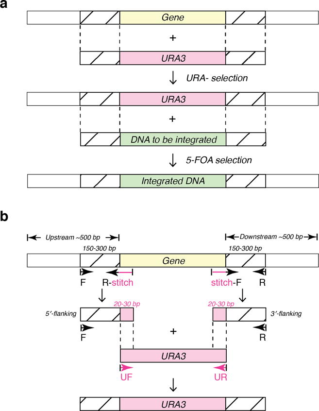
(a) Scheme of PCR-mediated two-step yeast transformation. During the first transformation, the targeted gene (yellow) is replaced by linear URA3 gene (pink) with flanking DNA (striped). The flanking DNA overlaps with yeast’s endogenous sequences so it can be integrated into yeast genome through homologous recombination. In the second step, the PCR product containing the target gene with intended modifications (green) replaces the URA3 in the genome via 5-FOA selection. (b) Scheme of primer design for generating URA3-containing PCR product. To generate a sequence with flanking DNA that overlaps with yeast genome, primer pairs that are upstream and downstream of the targeted sequence are obtained. The target sequence (yellow) together with ~500 bp both up- and downstream is selected, and the sequence is run through a primer design tool to obtain forward and reverse primers that are within ~150–300 bp from the targeted sequence (“F” and “R”). Next, pairs of primers are designed to stitch the flanking yeast sequence with URA3. To generate the stitching primer for upstream, 20–30 bp upstream of the 5′ end of the targeted site is combined with the first 20–30 bp of the 5′ end of the URA3 (pink), and then converted into its complementary sequence (“R-stitch” primer). To make the downstream stitching primer, the last 20–30 bp of the 3′ end of URA3 is combined with 20–30 bp downstream of the targeted site (“stitch-F” primer). Using yeast genome as template, the 5′-flanking sequence (along with the first 20–30 bp of the URA3 gene) can now be amplified with the “F” and “R-stitch” primers by PCR, while the 3′-flanking region can be amplified with the “stitch-F” and “R” primers. “UF” (5′-GTGATTCTGGGTAGAAGATCGG) and “UR” (5′-CGATGATGTAGTTTCTGGTTTTTAA) primers are used to amplify URA3 with its promoter and terminator. The final PCR product can then be generated using “F” and “R” as primers and the mixture of 5′-flanking DNA, 3′-flanking DNA, and URA3 as template. The same scheme applies for the second step of the yeast transformation, wherein the modified gene of interest (green in a) replaces the URA3 gene via homologous recombination.
3.1.1 Primer design for PCR
Because of the high efficiency homologous recombination mechanism in yeast, foreign DNA can readily be incorporated into the yeast genome. For homologous recombination to occur, the flanking sequences of the insertion gene must overlap with the 5′ and 3′ ends of the endogenous gene. To achieve good transformation efficiency, primers must be designed to ensure an adequate length of overlap between the flanking sequences of the insertion and the 5′ and 3′ ends of the endogenous gene (see Note 5).
Locate the dynein heavy chain gene (DYN1) in the Saccharomyces Genome Database (SGD), and obtain the genomic DNA sequence with ± 1kb (see Note 6).
Locate the site in the gene for the insertion, deletion, or mutation, and then select the sites for the flanking sequences (~500 bp upstream from the beginning and ~500 bp downstream from the end of the site) (see Note 7).
Design a pair of primers, 20–30 bp in length, that are ~150–300 bp upstream and downstream of the targeting site (designated “F” and “R” in Fig. 1b) (see Note 8). Make sure the reverse primer has the reverse complementary sequence of the targeted sequence.
Next, stitching primers need to be designed. To generate the stitching primer for the upstream flanking region, combine 20–30 bp upstream of the 5′ end of the targeted site with 20–30 bp of the 5′ end of the URA3 gene, and then convert it to its complimentary sequence (the “R-stitch” primer in Fig. 1b). For the downstream flanking region, combine 20–30 bp of the 3′ end of URA3 with 20–30 bp downstream of the targeted site as the “stitch-F” primer (Fig. 1b). The 5′-flanking sequence (with the URA3 overhang) can then be amplified with “F” and “R-stitch” primers, and the 3′-flanking sequence with “stitch-F” and “R” primers, using the yeast genome as a template (see Section 3.1.2 for gene amplification protocol).
The URA3 gene with its promoter and terminator can be amplified using the following primers: 5′-GTGATTCTGGGTAGAAGATCGG (“UF” in Fig. 1b) and 5′-CGATGATGTAGTTTCTGGTTTTTAA (“UR” in Fig. 1b). Note that URA3 of Kluyveromyces lactis is used instead of URA3 of S. cerevisiae to prevent undesirable recombination with its endogenous site.
The final gene insertion product can now be generated using “F” and “R” as primers and the mixture of 5′-flanking DNA, 3′-flanking DNA, and URA3 as template, as described in Section 3.1.2.
3.1.2 Generation of linear double-stranded DNA
PCR is used to generate linear double-stranded DNA for yeast transformation. Protocols for PCR have been well established, and the optimization and troubleshooting of PCR have been extensively reviewed [57,58]. Here we only intend to provide a standard PCR protocol using KOD hot start DNA polymerase, which is sufficient to handle reactions described in this chapter (see Note 9).
Create master-mix aliquots for 50 μL PCR reactions: Pre-mix 500 μL 10× reaction buffer, 500 μL dNTPs (2 mM each), 300 μL 25 mM MgSO4, and 3.2 mL ddH2O, aliquot into PCR tubes in 46 μL volumes, flash-freeze and store at −20 °C. For each reaction, only the primers, template, and DNA polymerase need to be added.
Prepare primers: Dissolve the primers in 10 mM Tris buffer to 10 μM final concentration. Flick the tubes several times to help dissolving, do not sonicate. Store at 4 °C short term (up to one week), and −20 °C long term (see Note 10).
PCR: Take out one master-mix PCR aliquot from the freezer, add 1.5 μL of each primer, 1 μL 10 ng/μL template (if the template is genomic yeast DNA, see steps 8–9 in Section 3.1.3), and 0.5 μL DNA polymerase, mix well. Apply standard cycling conditions to set up and start PCR. Purify the PCR products using the DNA cleanup kit. Measure the DNA concentration using the NanoPhotometer and verify the PCR products by DNA electrophoresis.
Prepare agarose gel: Based on the size of PCR products, choose a suitable percentage (w/v) of the agarose gel for DNA electrophoresis and calculate the weight of agarose for a 20 mL gel. Measure the agarose in a 50 mL conical tube, add 20 mL of 0.5× TBE buffer, and microwave the solution to dissolve the agarose. Do not completely tighten the cap, and make sure it does not boil. Once the gel cools down slightly, add 2 μL of DNA gel stain, mix well, and pour into the blueGel gel box with appropriate comb(s) in place. Allow the gel to cool down to solidify. Put the gel tray into the blueGel chamber, fill with 0.5× TBE buffer until it covers the gel, and gently pull out the comb.
Prepare and load the samples: For each sample, mix 1 μL of DNA ladder or PCR product, 1 μL of 5× Orange G loading dye, and 3 μL of ddH2O in a 0.5 mL tube. Carefully load the samples into the wells, and run for 30–45 min.
Visualize DNA: Visualize the bands using blue light. If a PCR product is clean and its size is as expected, store the PCR product from Step 3 a 4 °C for short term or at −20 °C for long term.
Purify DNA via agarose gel: If there are side products, use gel purification to extract the correct product. Prepare 50 mL agarose gel with 5 μL of DNA gel stain, pour into the B1A gel tray, and insert the B1A-6 comb with 1.5 mm thickness. Allow the gel to solidify. Put the gel into the gel box, fill both chambers with 0.5× TBE until it covers the gel, and gently pull the comb out. Mix 30 μL of the PCR product from step 3 and 7.5 μL of 5× Orange G loading dye in a 0.5 mL tube. Carefully load the sample into a well. Run at 100 V for 30–45 min (see Note 11). Weigh a 2 mL tube on a fine balance and zero the balance. Carefully cut the correct DNA product out using a clean razor and put it into the 2 mL tube, measure the weight, and purify it with the DNA cleanup unit.
3.1.3 Transformation of yeast cells with PCR products
Various methods have been developed for yeast transformation [59], with the LiAc/carrier DNA/PEG method being one of the standard methods [60,61]. Here, we apply the Frozen-EZ Yeast Transformation II Kit™ instead, which is easier and faster to use, since it does not require carrier DNA and heat shock (see Note 12). Below, we describe how to transform yeast cells with DNA products and for how to verify a successful transformation. The protocol (steps 1–12) is executed twice, first with the URA3-containing PCR product, then with the target DNA (to displace the URA sequence inserted in the first transformation). All steps that involve yeast cells must be performed using sterile techniques.
Take out a glycerol stock of the mother strain (first transformation) or the yeast strain with the inserted and verified URA sequence (second transformation) from the −80 °C freezer, and place it on dry ice to prevent melting. Use a sterile wooden applicator to scrap yeast cells from the tube, and streak onto a YPD plate. Parafilm the edges of the plate and incubate at 30 °C for 2–3 days until colonies are large enough (~1–2 mm in diameter).
Flame the tip of a metal tweezer and use the tweezer to pick a sterile 200 μL pipette tip. Scoop a single colony from the plate and drop the pipette tip into 3–5 mL of 2×YPD media to start the inoculation. Allow the cells to grow overnight at 30 °C with shaking.
Measure the OD600 of the overnight culture (saturated at OD600 ~40) and dilute an appropriate volume of the culture into 10 mL 2×YPD to begin the growth at a starting OD600 of 0.2. Grow for ~4–6 hrs with agitation at 30 °C to reach log phase.
Centrifuge the culture at 1000 rcf for 3 min to pellet the cells. Discard the supernatant and use residual liquid to resuspend the cells, and then transfer to a sterile 2 mL tube.
Proceed to transform the yeast cells with the URA3-containing PCR products (first transformation) or with the DNA target sequence to displace URA3 (second transformation) using the Frozen-EZ Yeast Transformation II Kit™ as specified by the vendor.
Resuspend yeast cells in 2 mL of 2×YPD and shake at 30 °C for 2 hrs to recover (see Note 13).
Pellet the cells at 1000 rcf for 30 sec and remove the supernatant, then wash once with 1 mL sterile ddH2O. Resuspend the cell pellet in 100–200 μL of sterile ddH2O, and then spread onto a SC/URA- selection plate (first transformation) or on a SC/5-FOA selection plate (second transformation). Parafilm the edge of the plate, and incubate at 30 °C for 2–3 days.
Verify that the yeast cells have correctly incorporated the PCR products by using PCR to amplify the sequence of interest using the transformed yeast genome as the template, and then sequence the PCR products. To do so, mark 4–8 colonies on the plate. For each colony, use a 200 μL pipette tip to pick half a colony and resuspend in 40 μL of 20 mM NaOH. Boil for 10 min, then vortex for 20 s, and centrifuge at max speed for 3 min to remove cell debris (for the URA insertion step, 1–2 colonies are usually sufficient).
Set up PCR reactions as in step 3 in Section 3.1.2. Use 2 μL of the supernatant of the lysed cells of the previous step as template for a 50 μL PCR reaction. Extend the annealing time to 30 sec, and use 35 cycles instead of 25 cycles.
Verify the PCR products by DNA electrophoresis as described in steps 4–6 in Section 3.1.2.
Choose and purify the PCR products that have the correct size, and send for sequencing.
Once the sequence is confirmed, pick the correct colony and inoculate in 5 mL 2×YPD as in step 2. After overnight growth, add 1 mL of the overnight culture and 0.5 mL of sterile 50% glycerol to a cryogenic tube. Store at −80 °C (see Note 14).
3.2 Yeast growth and harvest
3.2.1 Dynein expressed behind native promoter
Yeast dynein’s only known function is nuclear positioning during cell division [62,63]. It is therefore customary to harvest yeast cells during the log phase when the cells are actively dividing, with the assumption that dynein expression is highest during cell division.
Inoculate the pre-culture: Streak the yeast cells and start the pre-culture as in steps 1–2 in Section 3.1.3.
Grow into log phase: Inoculate 45 mL of 2×YPAD media with 5 mL of the overnight culture in a 250 mL sterile flask and shake at 30 °C overnight, then add the culture into a 6 L flask containing 1.75 L 2×YP solution and 200 mL sterile dextrose solution. Shake at 30 °C for 6–8 hrs.
Harvest the cells: Distribute the 2 L cell culture evenly between two 1 L centrifuge bottles and weigh out and balance both bottles, then harvest the cells by centrifugation at 4000 rcf for 3 min at 4 °C.
Wash the cells: Discard the supernatants of both bottles, and resuspend the pellet of one bottle with 200–300 mL ddH2O. Transfer the resuspended cells into the other bottle with the remaining pellet and add an additional 200–300 mL of ddH2O. Resuspend the pellet, and fill up the bottle to approximately 1 L. Weigh out and balance the bottle with a centrifuge bottle containing 1 L ddH2O and harvest the cells again by centrifugation at 4000 rcf for 3 min at 4 °C, then discard the supernatant.
Resuspend the cells with a 50 mL serological pipette using the residual water. If necessary, add stepwise 0.5 mL ddH2O until the pellet can be resuspended.
Drop-freeze the cell slurry into liquid nitrogen: Put a used pipette tip box or a plastic container in a styrofoam box and pour liquid nitrogen into the plastic container. Use the 50 mL serological pipette to drip the cell slurry dropwise into the liquid nitrogen (see Note 15). The frozen yeast bears some resemblance to popcorn at this state (see Note 16). Chill a metal spoon in liquid nitrogen and use it to transfer droplets into a 50 mL conical tube, then store the tube at −80 °C.
3.2.2 Dynein expressed behind galactose promoter
Yeast protein expression can be induced by galactose via GAL promoters. Here, the divergent GAL1-GAL10 promoter [64] is inserted before the dynein heavy chain gene [65]. However, this method can only be used for the tail-truncated dynein, which does not bind to and whose function does not dependent on the presence of the intermediate chain, light intermediate chain, and light chain of dynein [65,44,45]. Full-length dynein should not be expressed behind the galactose promoter, as this would result in motility defects and aggregation due to the substoichiometric concentrations of the dynein subunits [47,66]. For expression behind the galactose promoter, it is important to minimize the dextrose concentration during galactose induction, as the galactose promoter is strongly repressed by dextrose [67,68]. To circumvent this problem, just before the final induction step, the pre-culture is transferred to a media containing raffinose, which is a poor carbon source that relieves the dextrose-induced repression of the galactose promoter [68].
Streak the yeast cells on to a YPD plate and start the pre-culture as in steps 1–2 in section 3.1.3.
Inoculate the overnight culture into 45 mL of 1×YPR and shake for 8 hrs at 30 °C.
Inoculate the 1×YPR cell culture into a flask containing 1.75 L of 2×YP solution and 200 mL sterilized galactose solution and shake for 18–24 hrs at 30 °C.
Follow steps 3–6 in Section 3.2.1 to harvest cells.
3.3 Purification of yeast dynein
The full dynein complex (Dyn1471kDa) is purified via its heavy chain, which contains a ZZ-tag at the N-terminus followed by a TEV cleavage site [65]. After cell lysis and an ultracentrifugation step, dynein is bound to IgG beads via the ZZ-tag. After washing the beads, dynein is cleaved from the IgG beads with TEV protease. The same method is used to purify tail-truncated dynein expressed behind the galactose promoter. The procedures, which are to be performed in the cold room if not specified otherwise, describe in detail how to purify and label dynein with a fluorescent dye.
Prepare the buffers
-
1
Lysis buffer (LB): Add 60 μL of 1 M DTT, 100 mM ATP∙Mg, 10 μg/mL pepstatin A, 10 μg/mL leupeptin, 300 μL of 100 mM pefabloc SC, 600 μL of 200 mM benzamidine, and 1.92 mL ddH2O to 12 mL of 5×LB to yield 15 mL of 4×LB. Then, add 6 mL 4×LB to 18 mL ddH2O to yield 24 mL 1×LB. Finally, add 288 μL of 25% (v/v) Triton X-100 to the remaining 9 mL of 4×LB. Keep on ice.
-
2
Tev release buffer (Tev): Add 10 μL of 1 M DTT, 100 mM ATP, 50 μL of 100 mM pefabloc SC, 80 μL 25% (v/v) Triton X-100 to 10 mL 1×Tev. Keep on ice.
Lyse the cells
-
3
Pre-chill a Type 70.1 Ti rotor and a TLA-110 rotor overnight in the refrigerator. Set the Beckman L7-65 ultracentrifuge and Beckman Optima TLX ultracentrifuge to 4 °C. Pre-chill four Type 70.1 Ti rotor tubes with caps, four TLA-110 rotor tubes, a 250 mL glass beaker, a 50 mL serological pipette, a glass Pasteur pipette, two chromatography columns, and a 50 mL conical tube in the refrigerator.
-
4
Chill the coffee grinder and its plastic lid with liquid nitrogen for a few minutes. Test the functionality of grinder to make sure the blade is not stuck.
-
5
Take one conical tube with the frozen cell droplets from the −80 °C freezer. Transfer the droplets into the grinder and start grinding. Stop grinding as soon as a sign of melting appears on lid (~2 min).
-
6
Chill a metal spatula in liquid nitrogen. Use it to transfer the ground yeast powder into the pre-chilled 250 mL glass beaker, then add 3–4 mL 4× LB to the powder (~1 mL per 10 mL yeast powder).
-
7
Place the beaker immediately into a 37 °C bath to thaw the powder. Stir the powder gently with a plastic transfer pipette to thaw the powder evenly. When the mixture is close to completely thawed, place the glass beaker quickly back on ice (make sure that the beaker is surrounded by sufficient ice so that the upper level of the powder slurry is also close to the ice).
Clear the cell lysate
-
8
Use the pre-chilled 50 mL serological pipet to estimate the volume of the lysate and add an additional 4× LB to the solution to achieve a 1× LB final concentration.
-
9
Use the pipet to fill 2–4 Type 70.1 rotor tubes with roughly equal amounts of lysate. Fill the tubes to at least 2/3 of their volumes to prevent a potential collapsing of the tubes during centrifugation. Keep them on ice.
-
10
Wipe off the outside of the tubes with a Kimwipe to remove ice and water, and weigh each tube together with the cap. Transfer sample between tubes using a transfer pipette to balance each pair of tubes with a precision of ± 0.1 g, and then tighten the caps.
-
11
Dry the outside of the tubes again and place the pairs of equal weight in opposite positions in the Type 70.1 rotor. Tighten the rotor’s lid and place the rotor in a Beckman L7-65 ultracentrifuge. Once the vacuum is pulled below 250 micron, centrifuge at 65,000 rpm for 30 min at 4 °C. When the centrifugation finishes, take out the rotor. Set centrifuge to 18 °C and pull vacuum again to prevent condensation.
-
12
Put the tubes quickly on ice, and place the pre-chilled 50 mL conical tube also on ice. Transfer the supernatants of all tubes into the 50 mL conical tube using the pre-chilled glass Pasteur pipet. Leave ~0.5 mL in each tube to avoid transferring debris near the pellets.
-
13
After the supernatants have been transferred, pipette the solutions left in the tubes (without disturbing the pellets) into the TLA-110 rotor tubes, and balance the tubes. Place the tubes into the TLA-110 rotor, tighten the rotor lid, and place the rotor into the Beckman Optima TLX ultracentrifuge, then centrifuge at 100,000 rpm for 10 min at 4 °C.
-
14
Pipette the supernatants to the 50 mL conical tube from step 12. Reserve 2 μL of the lysate for SDS-PAGE gel analysis (LY in Fig. 2a).
-
15
Estimate the volume of the lysate and add ATP∙Mg and pefabloc SC to final concentrations of 0.1 mM and 0.5 mM, respectively.
Figure 2.
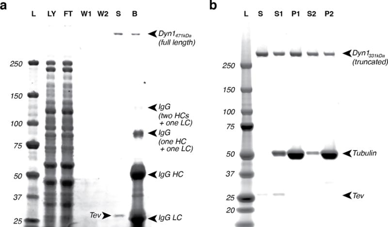
(a) A representative SDS-PAGE 4–12% gradient gel for dynein purification. The dynein is a full-length dynein expressed behind its native promoter (Dyn1471kDa) [65]. Due to the low concentration of native dynein, its associated subunits generally are not visible by InstantBlue staining. The lower bands in lane “B” are due to the IgG antibodies. L: molecular ladder, LY: lysate, FT: flow-through, W1: wash 1, W2: wash 2, S: sample, B: beads. (b) A representative SDS-PAGE 4–12% gradient gel for dynein microtubule binding release purification. In this example, the dynein is a truncated construct with an N-terminal GST tag (Dyn1331kDa) [65]. L: ladder, S: sample, S1: supernatant 1, P1: pellet 1, S2: supernatant 2, P2: pellet 2.
Purify dynein via its ZZ-tag
-
16
During centrifugation, take the IgG beads from the refrigerator and invert the tube several times until beads are completely resuspended. Pipette 250 μL of the bead slurry into the pre-chilled chromatography column using a 1000 μL pipette tip cut at its tip. Wash twice with 2.5 mL 1× LB using a serological pipette. Cap the bottom of the column when the total volume of the bead slurry and solution in the column decreases to ~500 μL. Resuspend the beads in the column using a cut 1000 μL pipette tip and then transfer the washed beads to the lysate in the 50 mL conical tube.
-
17
Tighten the cap of the conical tube and seal with parafilm. Nutate the tube at 4 °C for 1 hr.
-
18
Take the other pre-chilled column from refrigerator, and transfer the lysate into the column. Allow the solution to run through the column by gravity flow. Collect 2 μL of flow-through for gel analysis (FT in Fig. 2a).
-
19
Wait until the solution level is close to the bead surface. Use a fresh plastic transfer pipet to wash the beads with 3 × 5 mL of 1× LB. When ~100 μL solution remains on top of the beads (~350 μL total volume), cap the end of the column. Save 8 μL of the flow-through from the final wash step for gel analysis (W1 in Fig. 2a).
Label dynein with fluorescence dyes
-
20
Add HaloTag® ligand or SNAP-tag® ligand to a final concentration of ~10 μM to the column with the beads.
-
21
Incubate the beads at room temperature for 10 min. Stir gently using a metal spatula but avoid stirring beads onto the column walls.
-
22
Bring the column back to the cold room. Remove the cap and let the solution drain completely, then wash the beads first with the remaining 1× LB, then with 3 × 3 mL of 1× Tev. Following the final wash step, cap the column again once a volume of ~200 μL is left in the column. Take an 8 μL sample of the final flow-through for gel (W2 in Fig. 2a).
Cleave dynein from beads
-
23
Place a 2 mL microcentrifuge tube on ice and cut the tip of a 200 μL pipette tip. Resuspend beads by gently pipetting up and down, and transfer the beads to the 2 mL tube. Add 200 μL 1× Tev to the column and resuspend remaining beads, then transfer to the 2 mL tube. Repeat until all beads are transferred. Let the beads settle for 5 min, then remove supernatant until 150 μL of 1× Tev is left. Add 4 μL AcTev protease.
-
24
Parafilm the tube and incubate for 2 hrs at 4 °C while slowly rotating.
-
25
Centrifuge the tube for 30 sec at 1000 rcf at 4 °C using the refrigerated microcentrifuge. Save 8 μL of the supernatant for a gel sample “S” of native dynein or 5 μL for a sample of dynein expressed behind the galactose promoter (Fig. 2a).
-
26
Carefully pipette the supernatant into a 0.5 mL low retention microcentrifuge tube. Do not disturb the bead pellet. Pipette the solution that is close to the bead pellet to another tube, and then move the pipet tip into the bead pellet to get the last bit of solution. Centrifuge the second tube and carefully transfer the supernatant to the first tube (see Note 17). Aliquot into 50 μL volumes (Tev release aliquots). Drop tubes immediately into liquid nitrogen. Store at −80 °C. Use 200 μL of 1× Tev to resuspend the beads. Save 5 μL for gel (B in Fig. 2a).
-
27
Add 2 μL 5× SDS loading dye to each gel sample and add ddH2O to a final volume of 10 μL, then boil the samples for 10 min. Set up a bis-tris 4–12% gel in the minigel box, fill the chambers with 1× running buffer, load the samples and run for 50 min at 200 V. Stain the gel with InstantBlue, and scan with an Odyssey® imaging system (see Note 18).
3.4 MT binding and release purification of yeast dynein
In a second affinity purification step, a MT binding and release assay is performed to remove non-functional and/or aggregated dynein motors and other impurities (see Note 19). Dynein is mixed with MTs in the absence of ATP (strong MT-binding state) and then released from MTs in the presence of ATP (weak MT-binding state).
3.4.1 Polymerization of MTs
Add 1 μL 0.1 M DTT and 0.2 μL 10 mM paclitaxel to both 100 μL BRB80 with 10% glycerol and to 100 μL glycerol cushion.
Dilute 1 μL 10 mM paclitaxel in 49 μL DMSO for a concentration of 0.2 mM.
Add 0.2 μL 25 mM GTP∙Mg to 5 μL 5 mg/mL tubulin for a final concentration of 1 mM GTP and incubate at 37 °C for 15 min. Then add 0.7 μL 0.2 mM paclitaxel to the solution to stabilize the MTs. Mix well by gentle pipetting (do not vortex).
Add 60 μL glycerol cushion to a TLA-100 rotor tube, carefully pipette the MT solution on top of the cushion, and mark the outside edge of the tube with a permanent marker to help find the pellet position after the centrifugation. Place the tube inside the TLA-100 rotor with the mark facing outward and place a balance tube in the opposite rotor position. Centrifuge at 80,000 rpm for 10 min at room temperature.
Remove the supernatant, gently wash the pellet with 4×20 μL BRB80 with 10% glycerol, and resuspend the pellet in 5 μL BRB80 with 10% glycerol. Store at room temperature (see Note 20).
3.4.2 MT binding and release purification
Add 1 μL 0.1 M DTT and 0.2 μL 10 mM paclitaxel to 100 μL sucrose cushion and 2 μL 0.1 M DTT and 0.4 μl 10 mM paclitaxel to 200 μL wash buffer, mix well.
Add 2 μL 5× SDS loading buffer and 3 μL of ddH2O to each of five 0.5 mL “gel-loading tubes” for SDS-PAGE gel analysis.
Thaw an aliquot of 50 μL Tev release dynein. Add a 5 μL sample to one gel-loading tube and label with “S” for “sample” (Fig. 2b), then flash-freeze the tube.
Add 0.1 μL 10 mM paclitaxel to the dynein solution, mix well by gentle pipetting (do not vortex).
Add 5 μL of the polymerized 5 mg/mL MT solution (prepared in Section 3.4.1) to the dynein solution and incubate at room temperature for 5 min to allow dynein to bind to the MTs.
Add 100 μL sucrose cushion into a clean TLA-100 tube, carefully layer the MT/dynein solution onto the cushion, and mark the outside edge of the tube with a permanent marker. Place the tube inside the TLA-100 rotor with the mark facing outward and place a balance tube in the opposite rotor position. Centrifuge at 40,000 rpm for 10 min at 25 ˚C.
Add 5 μL of the supernatant to a gel-loading tube and label with “S1” (supernatant 1, Fig. 2b), then flash-freeze the tube.
Remove the supernatant and cushion carefully. Wash the pellet gently with 20 μL wash buffer, then remove wash buffer.
Resuspend the pellet with 52 μL wash buffer and add a 5 μL sample to one of the three remaining gel-loading tubes and label with “P1” (pellet 1, Fig. 2b), then flash-freeze the tube.
Add 3 μL 100 mM ATP∙Mg to the resuspended pellet and mix well. Incubate at room temperature for 2 min, then centrifuge at 40,000 rpm for 5 min at 25 ˚C.
Chill a 0.5 mL low-retention microcentrifuge tube on ice and transfer the supernatant from the TLA-100 tube to the low-retention microcentrifuge tube. Take a 5 μL sample and add it to one of the two remaining gel-loading tubes and label with “S2” (supernatant 2, Fig. 2b), then flash-freeze the tube. Aliquot the remaining dynein-containing supernatant into 1.5 μL volumes using PCR tubes. Flash-freeze the aliquots and store at −80 ˚C.
Wash the pellet with 20 μL wash buffer, remove the wash buffer, and resuspend pellet in 50 μL wash buffer. Add a 5 μl sample of the resuspended pellet to the last remaining gel-loading tubes and label with “P2” (pellet 2, Fig. 2b), then flash-freeze the tube.
Analyze the saved gel samples using SDS-PAGE gel electrophoresis as described in step 27 in Section 3.3.
3.5 Polymerization of MTs for single-molecule assays
Functionalized tubulins, such as fluorophore-tagged tubulin and biotinylated tubulin, are frequently employed to visualize and/or immobilize MTs [69,70,46,45]. Functionalized tubulins are either commercially available, or can be prepared as previously described in detail [53]. Usually, functionalized tubulins are mixed with unlabeled tubulin at a low ratio, and incorporated into MTs during polymerization.
3.5.1 Polymerization of functionalized MTs
Add one aliquot of fluorescently labeled-tubulin (1 μg) and one aliquot of biotinylated-tubulin (1 μg) to one aliquot of unlabeled tubulin (5 μL of 5 mg/mL; 25 μg). Mix thoroughly and incubate for 10 min on ice.
Follow the protocol described in Section 3.4.1 to polymerize a mixture of functionalized and non-functionalized tubulin.
3.5.2 Polymerization of polarity-marked MTs
Polarity-marked MTs are used to distinguish between the plus and minus ends of MTs. Tubulin with a high ratio of fluorophore-labeled-to-unlabeled tubulin is first polymerized to create bright MT seeds, then a tubulin mixture with a lower ratio of labeled-to-unlabeled tubulin is added to continue polymerization off the ends of the seeds. This procedure yields fluorophore-labeled MTs with bright minus ends [71]. However, MTs can join end-to-end or anneal over time at room temperature [72] so that the bright seeds no longer mark the end of the MT. It is therefore recommended to prepare the polarity-marked microtubules fresh on the day of the experiment.
Add 0.2 μL of 1 M DTT and 2 μL of 100 mM GTP to 200 μL BRB80 with 10% glycerol, and keep on ice.
Dilute 1 μL 10 mM paclitaxel in 49 μL DMSO to 0.2 mM.
To prepare the tubulin stock for the seeds (S), take one vial of the rhodamine-labeled tubulin (20 μg) from the freezer, add 12 μL of the buffer prepared in step 1 to solvate the tubulin, and incubate on ice. If biotinylated tubulin is needed, add the 12 μL solution with the rhodamine-labeled tubulin to a vial of biotinylated tubulin (20 μg) to solvate the biotin-tubulin. Aliquot ten 0.5 μl volumes and flash-freeze in liquid nitrogen. Store at −80 °C
To prepare the tubulin stock for MT polymerization (T), add the remaining labeled tubulin solution (7 μL) to an aliquot of unlabeled tubulin (5 μL of 5 mg/mL), mix well by gentle pipetting, then incubate on ice for 10 min. Add 40 μL BRB80 with 10% glycerol, and mix well, then aliquot into ten 5 μl volumes and flash-freeze in liquid nitrogen. Store at −80 °C.
Polymerization of polarity-marked MTs: Take one aliquot each of the “seeds” stock (S) and the “polymerization” stock (T) from the freezer. Incubate S at 37 °C for 5 min, add T to S, and incubate at 37 °C for 15 min, then add 0.7 μL of 0.2 mM paclitaxel.
Follow steps 4–5 of Section 3.4.1 to remove free tubulin.
3.6 Coverslip preparation for MT attachment
There are a number of different approaches for attaching MTs to glass surfaces, the choice of which depends on the assay to be performed. Here, we begin by describing two easy-to-use protocols for the surface attachment of MTs for single-molecule fluorescence and optical trapping assays. While both techniques are based on the non-covalent attachment of MTs to glass surfaces, one technique relies on the surface attachment via functionalized (biotinylated) MTs and the other uses non-functionalized MTs by taking advantage of the electrostatic interactions between the negatively charged tubulins and the positive charge of surface-attached PLL. Both techniques result in rigidly attached MTs for up to ~30 minutes in the presence of blocking reagents. Surface-attachment of biotinylated MTs through streptavidin-biotin linkages is a commonly used method. Note, however, it results in the random orientation of MTs on the coverslip surface. This is less ideal for optical trapping experiments, where it is preferable to perform force measurements along a fixed axis. In contrast, the PLL-based method results in MTs that are aligned with the long axis of the slide chamber, because surface-attachment occurs immediately as a result of the laminar flow and the favorable initial electrostatic interactions when MTs come in contact with the surface-bound PLL while the solution is flown into the chamber. Lastly, we describe a new protocol that combines both techniques and results in aligned MTs and in rigid surface attachment for more than an hour.
3.6.1 Immobilization via biotin-streptavidin interactions
The binding of biotinylated MTs to BSA-biotin via streptavidin is routinely used to attach MTs to coverslip surfaces [69,73,74]. First, BSA-biotin is attached to the glass surface via non-specific interactions, and then streptavidin is applied to bind the surface-bound BSA-biotin specifically (Fig. 3a). Biotinylated MTs are then flown into the chamber and given sufficient time to rigidly bind to the streptavidin-coated surface. While this approach results in a random orientation of the attached MTs (Fig. 4a), it provides a straightforward and easy to use method for single-molecule fluorescence assays.
Figure 3.
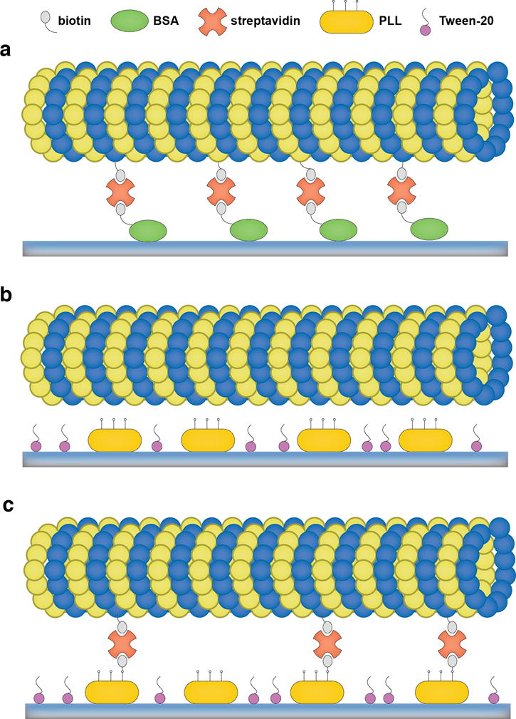
(a) Scheme of microtubule immobilization via BSA-biotin-streptavidin attachment. BSA-biotin (green) adsorbs to a coverslip surface, followed by streptavidin (orange) that is bound to biotin. MTs with biotinlyated tubulin are then immobilized via streptavidin. (b) Scheme of microtubule immobilization via PLL. PLL (yellow) adsorbs to a coverslip surface, followed by Tween-20 (purple), which blocks the surface. MTs are immobilized via electrostatic interactions with the amine groups of PLL. (C) For optical trapping assays, the amine groups of PLL can be sparsely labeled with NHS-biotin, and biotinylated MTs can be further tightly attached via streptavidin.
Figure 4.
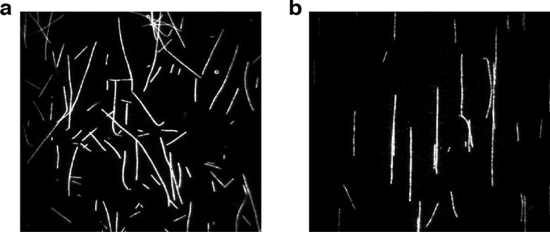
(a) Micrograph of MTs attached to a coverslip surface via BSA-biotin-streptavidin attachment. (b) Micrograph of MTs attached to a coverslip using PLL.
Coverslip cleaning: Place coverslips in a coverslip rack and submerge in 1 M HCl overnight. Rinse extensively with ddH2O, then sonicate sequentially in 30% ethanol, 50% ethanol, and absolute ethanol for 30 min/solution. Store the coverslips in ethanol until usage (see Note 21).
Coating with biotin-BSA: Assemble a flow chamber as described before in detail [53] using the coverslips cleaned in step 1. Flow 15 μL biotin-BSA into the chamber and incubate for at least 30 min (see Note 22). Dilute 4 μL of 50 mg/mL BSA into 196 μL of BRB80-s and wash the chamber with 2×20 μL BRB80-s with BSA.
Binding of streptavidin: Add 16 μL of BRB80-s with BSA to an aliquot of 4 μL 5 mg/ml streptavidin, mix well, and flow into the flow chamber. Incubate at room temperature for 8–10 min, and then wash with 2×20 μL of BRB80-s with BSA.
Binding of MTs: Dilute the MT solution prepared in Section 3.5.1 (fluorescently labeled and biotinylated MTs) or Section 3.5.2 (fluorescently labeled, polarity-marked and biotinylated MTs) 1:10 in BRB80-s, and then add 1 μL of the diluted MT solution to 19 μL BRB80-s with BSA (to create a 1:200 final dilution of the MT solution). Flow 20 μL of the diluted MT solution into the chamber and incubate at room temperature for at least 15 min. Wash twice with 20 μL BRB80-s with BSA. Proceed with step 1 of Section 3.7.1 to perform single-molecule dynein motility experiments.
3.6.2 Immobilization via poly-L-lysine
While MT surface-attachment based on biotin-streptavidin interactions is a commonly used method, it is rather time consuming due to the laborious preparation of coverslips and the long incubation times. In addition, biotin-BSA and streptavidin are costly, and the method results in the random orientation of MTs on the coverslip surface, which makes this approach less useful for many optical trapping assays.
In order to align MTs with the long axis of the flow chamber, AEAPTES (N-(2-aminoethyl)-3-aminopropyl triethoxysilane)-coated coverslips can be used to immobilize MTs via covalent binding [53], and we have commonly used this method in our laboratory [45,46]. However, the coating of coverslips with AEAPTES is also time consuming, and generates hazardous waste. Most critically, AEAPTES is labile, resulting in inconsistencies in the coverslip surface coating if it is not fresh or stored in a vacuum or inert gas [53]. Therefore, we have adopted the use of PLL-coated surfaces, a technique that is commonly used to facilitate the attachment of cell cultures to surfaces [75] (Fig. 3b). Like AEAPTES, PLL binds MTs via its positively charged amine groups, but its handling is significantly easier and more time- and cost-effective than using AEAPTES. And most importantly, as is the case for AEAPTES-based immobilization, MTs immobilized with PLL are well aligned with the long axis of the flow chamber due to the combination of the favorable initial electrostatic interactions with the positively charged surface and the laminar flow induced by the filling of the chamber (Fig. 4b).
Coverslip cleaning: Place coverslips in a coverslip rack and submerge the coverslips in 25% (v/v) HNO3 for 10 min. Rinse with ddH2O, then submerge in 2 M NaOH for 2 min (see Notes 23 and 24). Extensively rinse with ddH2O, and then dry the coverslips on a heating block for 10–20 min.
Coating with PLL: Once the coverslips have cooled down, submerge them in 0.01% (w/v) PLL solution for 2 min (see Note 25), and subsequently in Tween-20 (0.1%) overnight to block the surface (see Note 26). The coverslips can be stored in Tween-20 solution for one week. Before usage, wash a coverslip with ddH2O and dry it with filtered, compressed air or vacuum, then assemble a flow chamber.
Binding of MTs for single-molecule fluorescence and/or optical trapping experiments: Dilute the MT solution prepared in Section 3.5.1 or Section 3.5.2 1:10 in BRB80-s, and then add 1 μL of the 1:10 diluted MT solution to 19 μL BRB80-s to create a 1:200 final dilution. Flow 20 μL of the diluted MT solution into the chamber and immediately wash with 2 × 20 μL BRB80-s. Proceed with Section 3.7.1 to perform single-molecule dynein motility experiments or Section 3.7.2 to perform optical trapping experiments.
3.6.3 Immobilization via PLL and biotin-streptavidin interactions
The MT immobilization method solely based on surface-bound PLL (Section 3.6.2) will suffice for single-molecule in vitro experiments if the experiments can be carried out within ~30 minutes. However, the frequently used blocking reagent casein, which is very effective in passivating positively-charged surfaces due to its highly negatively charged N-terminal region [76], competes with MTs for attachment to surface-bound PLL (and likely also shields the positive charges of PLL). This results in increasingly floppy MTs and the eventual dissociation, making finding well-aligned and rigidly bound MTs increasingly difficult. To improve the time of rigid MT attachment for optical trapping assays that often last for more than an hour, we have established a new protocol that combines electrostatic and biotin-streptavidin interactions for the immobilization of MTs to coverslip surfaces (Fig. 3c). While the use of the PLL-coated surfaces facilitates the rapid attachment of MTs to the coverslip surface with their long axes aligned with the long axis of the flow chamber, the additional streptavidin/biotin-based surface binding of MTs ensures that the rigid attachment is maintained for extended times. To do so, we bind NHS-biotin covalently to a fraction of the amine groups of the surface-bound PLL and use biotinylated MTs.
Submerge a coverslip coated with PLL and Tween-20 (prepared in steps 1 and 2 of Section 3.6.2) for 3–5 min in 0.1% PLL solution (see Note 27), and then wash it with ddH2O. Dry the cover slip with filtered, compressed air or vacuum and assemble it into a flow chamber.
Add 8 μL of coupling buffer to 2 μL of 10 mM EZ-link NHS-biotin, and flow the solution into the chamber. Incubate at room temperature for 5 min, and then wash the chamber with 200 μL ddH2O. Dry the flow chamber with filtered, compressed air or vacuum, and dilute 4 μL 5 mg/mL streptavidin in 16 μL HME30 to yield 1 mg/mL streptavidin, then flow into the chamber. Incubate at room temperature for 5 min, then wash four times with 20 μL HME30. Dry the chamber with filtered, compressed air or vacuum.
Dilute 0.2 μL of polarity-marked, rhodamine-biotin-MTs (prepared in Section 3.5.2) in 20 μL of HME30-s, flow the diluted MT solution through the chamber, and then immediately wash with 2 × 20 μL of HME30-s (the more time passes before the wash step, the more MTs will attach to the coverslip surface with random orientations). Proceed with step 1 of Section 3.7.2 to perform optical trapping experiments on dynein.
3.7 Single-molecule assays
Over the past three decades, single-molecule techniques have provided significant insights into the functions and mechanisms of motion- and force-generating mechanoenzymes, with applications across multiple disciplines [77]. In the cytoskeletal motor field, the most commonly used single-molecule techniques are based on single-molecule fluorescence measurements [78,79,65] and force measurements using optical tweezers [80–84,45,46] (or a combination of both [85]). As the technical details of both methods have been described and discussed in detail elsewhere, here we only describe the remaining steps needed to successfully set up single-molecule fluorescence and optical trapping experiments on dynein using the MT-filled slide chambers prepared in Sections 3.6.1–3.6.3. For more details on these assays, please refer to references [86–88,54].
3.7.1 Single-molecule fluorescence assay
In single-molecule fluorescence motility assays, the velocity and run length of a processive motor along MTs can be tracked and measured via a fluorescent tag using TIRF microscopy [89,90]. Below, we describe the remaining steps that have to be executed to visualize the motility of recombinant yeast dynein.
Prepare a slide chamber with surface-attached MTs as described in Section 3.6.1 (MT immobilization via biotin-streptavidin interactions only), Section 3.6.2 (MT immobilization via PLL only) or Section 3.6.3 (MT immobilization via both PLL and biotin-streptavidin interactions). Take out one aliquot (200 μL) of HME30-s from the −20 °C freezer.
Add 2.5 μL of 25 mg/mL β-casein to 47.5 μL of HME30-s (for a final concentration of 1.25 mg/ml), and wash the slide chamber with 2 × 20 μL of HME30-s with casein.
To a fresh 0.5 mL tube, add 43 μL of HME30-s, 5 μL β-casein, 0.5 μL ATP, 0.5 μL POC, and 1 μL of the dynein MT binding release fraction (prepared in Section 3.4.2). Mix well and flow 2 × 20 μL of the mixture into the flow chamber, then seal the chamber with vacuum grease.
Mount the slide chamber to the microscope stage using a sufficient amount of immersion oil, and perform TIRF motility experiments as detailed elsewhere [90,89].
Analyze the data by creating Kymographs via ImageJ (Fig. 5a) or by applying a single-particle tracking software such as FIESTA [91].
Figure 5.
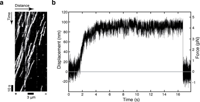
(a) A representative kymograph of full-length dynein. The acquisition rate was 500 ms/frame. (b) A representative stall trace of full-length dynein. The spring constant k was 0.045 pN/nm.
3.7.2 Optical trapping assay
Optical tweezers [52] is an invaluable tool to probe the nanometer-scale displacements and piconewton force generation of individual dynein molecules. In the assay described here, full-length yeast dynein is coupled to anti-GFP antibody-coated 1-μm polystyrene beads through the N-terminal GFP-tag on the motor’s tail. Dynein-coated beads are captured with a fixed position optical trap and placed above a surface-bound MT using the nanopositioning stage of the microscope. Upon MT binding, a dynein-coated bead moves along the MT away from the trap center until the motor stalls and eventually releases (Fig. 5b). As we have described the technical aspects of these experiments in detail before [48,92,54], here we simply outline the final steps necessary to set up a trapping experiment using recombinant dynein.
In a 0.5 mL tube, dilute 1 μL of anti-GFP beads in 49 μL of HME30, and parafilm the tube and store the diluted beads at 4 °C.
Take out one aliquot (200 μL) of HME30-s from the −20 °C freezer, and thaw in a 37 °C bath or in your hand.
Prepare a slide chamber with surface-attached MTs as described in Section 3.6.3 (MT immobilization via PLL and biotin-streptavidin interactions).
Add 2.8 μL of 25 mg/mL α-casein to the remaining 140 μL HME30-s to a final concentration of 0.5 mg/ml, and use the solution to dilute dynein to a concentration that results in MT binding by <50% of beads in the final assay, implying binding by single motors[93] (start with a dilution of 1:1,000 achieved by serially diluting the motor in tenfold steps).
Briefly sonicate 4 μL of diluted beads in a 0.5 mL low-retention tube.
Add 4 μL of the diluted dynein to the beads, mix well by gentle pipetting, then incubate on ice for 10 min.
Add 0.4 μL of POC, 0.4 μL of ATP, 0.4 μL of PEP, and 0.4 μL of PK (ATP regeneration system) to 31 μL of HME30-s with α-casein, and mix well, then add the mixture to the aliquot with the dynein-beads solution. Flow 2× 20 μL of the dynein-bead mixture into the chamber, and seal the chamber with vacuum grease.
Perform data collection and data analysis as previously described [54,48,92].
Acknowledgments
The authors would like to thank Lisa Baker for her help in editing the manuscript. The authors are supported by NIH Grant R01GM098469.
Footnotes
Normally, standard PCR machines are used. However, if a laboratory only needs to do routine PCR in a small scale, the miniPCR™ machine could be an inexpensive option. We have tested it for amplifying DNA between 150 bp – 9 kbp using different DNA polymerases such as KOD hot start DNA polymerase, Q5® (NEB), and Phusion® (NEB), and the yield and purity are comparable to those resulting from standard PCR machines.
Trolox is not very soluble. It is best to add HEPES, MgCl2, EGTA, and Trolox to a 50 mL conical tube and nutate overnight covered with aluminum foil, and then add DTT and paclitaxel before aliquoting.
Most yeast genes lack introns, and deletions of these introns generally do not affect cell growth, but extra care should still be taken when working with intron-containing genes [94].
While 5-FOA (5-fluoroorotic acid) is non-toxic, it can be converted into the toxic compound 5-flurouracil if URA3-encoded orotidine 5′-phosphate decarboxylase is present. For more details on PCR-based yeast gene engineering, please refer to references [56,95,96].
Although studies have shown that having only 30 bp overlap can lead to successful homologous recombination, 60 bp overlap is recommended for high efficiency transformation [97].
SGD is a specialized database for Saccharomyces cerevisiae, but other databases such as UniProt and NCBI can be used as well.
We use SerialCloner (v. 2-6-1) to do DNA and protein sequence analysis for molecular cloning but other software tools can be used as well.
Online primer design tools, such as Primer-BLAST (NCBI) and PrimerQuest (IDT DNA), can be used to obtain the primers.
Other high fidelity DNA polymerases can be used as well. In particular, when more difficult reactions need to be performed, it may be necessary to optimize PCR parameters or to choose a different DNA polymerase.
The primers can be dissolved in TE buffer to 100 μM as stock, which can be further diluted to 10 μM in 10 mM Tris buffer. The second dilution should not contain EDTA, which would interfere with the DNA polymerase.
Running the gel at a lower voltage may improve the resolution, but will result in a longer running time.
The mechanism underlying this transformation is not fully understood.
While this step could be skipped for URA selection, it is critical for 5-FOA selection: Without the recovery step, the colonies that appear on the SC/5-FOA plate will mostly be false positives, with mutations in the URA3 gene that disrupt its function, rather than having incorporated the desired DNA sequence.
It is always a good practice to store two tubes of each yeast strain, and put one strain in a separate box as a backup, in case the other tube is contaminated.
Do not let the pipette get too close to the liquid nitrogen as the cell slurry might freeze inside the pipette tip.
Depending on the yeast strain, the volume of the pellet varies between 25–40 mL (dysfunctional dynein causes cells to grow slower, resulting in a smaller yield).
We do not recommend using a membrane filter unit to separate the solution from the beads, since dynein tends to bind to membrane surfaces.
If quantification of the bands is needed, BSA or actin standards should be included on the gel as well.
MT binding and release purification may not be applicable for some dynein mutants. In this case, although more labor intensive, size exclusion chromatography [98] or sucrose density gradient centrifugation [99] can be applied, which are better techniques for removing aggregated dynein and impurities.
MTs are temperature sensitive and tend to disassemble in the cold in the absence of taxol. When maintained in the presence of taxol, MTs can be used for up to one week when stored at room temperature.
It is important to submerge the coverslips in ethanol for a few hours before usage, otherwise the surface is less hydrophilic, resulting in the reduced binding of BSA-biotin.
The longer the BSA-biotin incubates in the chamber, the higher its surface density, and therefore the MTs will bind more strongly later. We recommend preparing the flow chambers with BSA-biotin in the morning, storing them in a humidity box at room temperature, and using them in the afternoon. Alternatively, BSA-biotin can be incubated in the flow chamber in a humidity box overnight at 4 °C.
The HNO3 and NaOH solutions can be reused without losing their effects for a long time. However, it is a good practice to replace the solutions once a year.
The surfaces of coverslips treated with NaOH are hydrophilic, which is favorable for surface adsorption. However, this treatment also etches the glass surface and renders the surface uneven [100], which is undesirable for MT binding. Thus, the NaOH incubation time was optimized to result in a sufficient surface absorption of PLL while preventing the distortion of MTs.
The incubation time of the PLL solution is important. Increasing the incubation time can result in too high a density of PLL on the coverslip. While the MTs will bind rigidly for a longer period of time with a higher PLL density, the increase in positive charge along the surface of the coverslip can be disruptive to the motility of microtubule-associated motor proteins, which have positively-charged MT-binding domains.
Various surface blocking agents have been utilized to block coverslip surfaces to prevent non-specific binding. Besides Tween-20 and detergents such as Pluronic F-127 and Triton X-100, proteins such as BSA and casein, and polymers such as PEG have been used to block surfaces to various degrees of success. For single-molecule TIRF assays, other blocking agents can replace Tween-20. However, while BSA is a commonly used blocking agent in optical trapping assays, in our experience, casein is significantly more effective in preventing non-specific interactions between the beads and coverslip surface than BSA. It is therefore advised to rule out bead-surface interactions in the absence of motors when switching to a different blocking agent before an experiment is performed.
The increase in surface-bound PLL as a result of the second incubation with PLL is necessary to provide binding sites for the covalent attachment of NHS-biotin while leaving enough positively charged amine groups for electrostatic interactions with MTs.
References
- 1.Abe TK, Honda T, Takei K, Mikoshiba K, Hoffman-Kim D, Jay DG, Kuwano R. Dynactin is essential for growth cone advance. Biochem Biophys Res Commun. 2008;372(3):418–422. doi: 10.1016/j.bbrc.2008.05.008. [DOI] [PubMed] [Google Scholar]
- 2.Grabham PW, Seale GE, Bennecib M, Goldberg DJ, Vallee RB. Cytoplasmic dynein and LIS1 are required for microtubule advance during growth cone remodeling and fast axonal outgrowth. J Neurosci. 2007;27(21):5823–5834. doi: 10.1523/JNEUROSCI.1135-07.2007. [DOI] [PMC free article] [PubMed] [Google Scholar]
- 3.Kardon J, Vale R. Regulators of the cytoplasmic dynein motor. Nat Rev Mol Cell Biol. 2009;10(12):854–865. doi: 10.1038/nrm2804. [DOI] [PMC free article] [PubMed] [Google Scholar]
- 4.Tai CY, Dujardin DL, Faulkner NE, Vallee RB. Role of dynein, dynactin, and CLIP-170 interactions in LIS1 kinetochore function. J Cell Biol. 2002;156(6):959–968. doi: 10.1083/jcb.200109046. [DOI] [PMC free article] [PubMed] [Google Scholar]
- 5.Vallee RB, Williams JC, Varma D, Barnhart LE. Dynein: An ancient motor protein involved in multiple modes of transport. J Neurobiol. 2004;58(2):189–200. doi: 10.1002/neu.10314. [DOI] [PubMed] [Google Scholar]
- 6.Yamada M, Toba S, Yoshida Y, Haratani K, Mori D, Yano Y, Mimori-Kiyosue Y, Nakamura T, Itoh K, Fushiki S, Setou M, Wynshaw-Boris A, Torisawa T, Toyoshima Y, Hirotsune S. LIS1 and NDEL1 coordinate the plus-end-directed transport of cytoplasmic dynein. EMBO J. 2008;27(19):2471–2483. doi: 10.1038/emboj.2008.182. [DOI] [PMC free article] [PubMed] [Google Scholar]
- 7.Peeters K, Bervoets S, Chamova T, Litvinenko I, De Vriendt E, Bichev S, Kancheva D, Mitev V, Kennerson M, Timmerman V, De Jonghe P, Tournev I, MacMillan J, Jordanova A. Novel mutations in the DYNC1H1 tail domain refine the genetic and clinical spectrum of dyneinopathies. Hum Mutat. 2015;36(3):287–291. doi: 10.1002/humu.22744. [DOI] [PubMed] [Google Scholar]
- 8.Chen XJ, Xu H, Cooper HM, Liu Y. Cytoplasmic dynein: a key player in neurodegenerative and neurodevelopmental diseases. Sci China Life Sci. 2014;57(4):372–377. doi: 10.1007/s11427-014-4639-9. [DOI] [PubMed] [Google Scholar]
- 9.Gelineau-Morel R, Lukacs M, Weaver KN, Hufnagel RB, Gilbert DL, Stottmann RW. Congenital Cataracts and Gut Dysmotility in a DYNC1H1 Dyneinopathy Patient. Genes (Basel) 2016;7(10):85–92. doi: 10.3390/genes7100085. [DOI] [PMC free article] [PubMed] [Google Scholar]
- 10.Harms MB, Ori-McKenney KM, Scoto M, Tuck EP, Bell S, Ma D, Masi S, Allred P, Al-Lozi M, Reilly MM, Miller LJ, Jani-Acsadi A, Pestronk A, Shy ME, Muntoni F, Vallee RB, Baloh RH. Mutations in the tail domain of DYNC1H1 cause dominant spinal muscular atrophy. Neurology. 2012;78(22):1714–1720. doi: 10.1212/WNL.0b013e3182556c05. [DOI] [PMC free article] [PubMed] [Google Scholar]
- 11.Neveling K, Martinez-Carrera LA, Holker I, Heister A, Verrips A, Hosseini-Barkooie SM, Gilissen C, Vermeer S, Pennings M, Meijer R, te Riele M, Frijns CJ, Suchowersky O, MacLaren L, Rudnik-Schoneborn S, Sinke RJ, Zerres K, Lowry RB, Lemmink HH, Garbes L, Veltman JA, Schelhaas HJ, Scheffer H, Wirth B. Mutations in BICD2, which encodes a golgin and important motor adaptor, cause congenital autosomal-dominant spinal muscular atrophy. Am J Hum Genet. 2013;92(6):946–954. doi: 10.1016/j.ajhg.2013.04.011. [DOI] [PMC free article] [PubMed] [Google Scholar]
- 12.Niu Q, Wang X, Shi M, Jin Q. A novel DYNC1H1 mutation causing spinal muscular atrophy with lower extremity predominance. Neurol Genet. 2015;1(2):e20. doi: 10.1212/NXG.0000000000000017. [DOI] [PMC free article] [PubMed] [Google Scholar]
- 13.Strickland AV, Schabhuttl M, Offenbacher H, Synofzik M, Hauser NS, Brunner-Krainz M, Gruber-Sedlmayr U, Moore SA, Windhager R, Bender B, Harms M, Klebe S, Young P, Kennerson M, Garcia AS, Gonzalez MA, Zuchner S, Schule R, Shy ME, Auer-Grumbach M. Mutation screen reveals novel variants and expands the phenotypes associated with DYNC1H1. J Neurol. 2015;262(9):2124–2134. doi: 10.1007/s00415-015-7727-2. [DOI] [PMC free article] [PubMed] [Google Scholar]
- 14.Ding D, Chen Z, Li K, Long Z, Ye W, Tang Z, Xia K, Qiu R, Tang B, Jiang H. Identification of a de novo DYNC1H1 mutation via WES according to published guidelines. Sci Rep. 2016;6:20423. doi: 10.1038/srep20423. [DOI] [PMC free article] [PubMed] [Google Scholar]
- 15.Weedon MN, Hastings R, Caswell R, Xie W, Paszkiewicz K, Antoniadi T, Williams M, King C, Greenhalgh L, Newbury-Ecob R, Ellard S. Exome sequencing identifies a DYNC1H1 mutation in a large pedigree with dominant axonal Charcot-Marie-Tooth disease. Am J Hum Genet. 2011;89(2):308–312. doi: 10.1016/j.ajhg.2011.07.002. [DOI] [PMC free article] [PubMed] [Google Scholar]
- 16.Reiner O, Carrozzo R, Shen Y, Wehnert M, Faustinella F, Dobyns WB, Caskey CT, Ledbetter DH. Isolation of a Miller-Dieker lissencephaly gene containing G protein beta-subunit-like repeats. Nature. 1993;364(6439):717–721. doi: 10.1038/364717a0. [DOI] [PubMed] [Google Scholar]
- 17.Vallee RB, Tai C, Faulkner NE. LIS1: cellular function of a disease-causing gene. Trends Cell Biol. 2001;11(4):155–160. doi: 10.1016/s0962-8924(01)01956-0. [DOI] [PubMed] [Google Scholar]
- 18.Poirier K, Lebrun N, Broix L, Tian G, Saillour Y, Boscheron C, Parrini E, Valence S, Pierre BS, Oger M, Lacombe D, Genevieve D, Fontana E, Darra F, Cances C, Barth M, Bonneau D, Bernadina BD, N’Guyen S, Gitiaux C, Parent P, des Portes V, Pedespan JM, Legrez V, Castelnau-Ptakine L, Nitschke P, Hieu T, Masson C, Zelenika D, Andrieux A, Francis F, Guerrini R, Cowan NJ, Bahi-Buisson N, Chelly J. Mutations in TUBG1, DYNC1H1, KIF5C and KIF2A cause malformations of cortical development and microcephaly. Nat Genet. 2013;45(6):639–647. doi: 10.1038/ng.2613. [DOI] [PMC free article] [PubMed] [Google Scholar]
- 19.Willemsen MH, Vissers LEL, Willemsen MAAP, van Bon BWM, Kroes T, de Ligt J, de Vries BB, Schoots J, Lugtenberg D, Hamel BCJ, van Bokhoven H, Brunner HG, Veltman JA, Kleefstra T. Mutations in DYNC1H1 cause severe intellectual disability with neuronal migration defects. J Med Genet. 2012;49(3):179–183. doi: 10.1136/jmedgenet-2011-100542. [DOI] [PubMed] [Google Scholar]
- 20.Fiorillo C, Moro F, Yi J, Weil S, Brisca G, Astrea G, Severino M, Romano A, Battini R, Rossi A, Minetti C, Bruno C, Santorelli FM, Vallee R. Novel dynein DYNC1H1 neck and motor domain mutations link distal spinal muscular atrophy and abnormal cortical development. Hum Mutat. 2014;35(3):298–302. doi: 10.1002/humu.22491. [DOI] [PMC free article] [PubMed] [Google Scholar]
- 21.Munch C, Sedlmeier R, Meyer T, Homberg V, Sperfeld AD, Kurt A, Prudlo J, Peraus G, Hanemann CO, Stumm G, Ludolph AC. Point mutations of the p150 subunit of dynactin (DCTN1) gene in ALS. Neurology. 2004;63(4):724–726. doi: 10.1212/01.wnl.0000134608.83927.b1. [DOI] [PubMed] [Google Scholar]
- 22.Puls I, Jonnakuty C, LaMonte BH, Holzbaur EL, Tokito M, Mann E, Floeter MK, Bidus K, Drayna D, Oh SJ, Brown RH, Ludlow CL, Fischbeck KH. Mutant dynactin in motor neuron disease. Nat Genet. 2003;33(4):455–456. doi: 10.1038/ng1123. [DOI] [PubMed] [Google Scholar]
- 23.Farrer MJ, Hulihan MM, Kachergus JM, Dächsel JC, Stoessl AJ, Grantier LL, Calne S, Calne DB, Lechevalier B, Chapon F, Tsuboi Y, Yamada T, Gutmann L, Elibol B, Bhatia KP, Wider C, Vilariño-Güell C, Ross OA, Brown LA, Castanedes-Casey M, Dickson DW, Wszolek ZK. DCTN1 mutations in Perry syndrome. Nat Genet. 2009;41(2):163–165. doi: 10.1038/ng.293. [DOI] [PMC free article] [PubMed] [Google Scholar]
- 24.Vilariño-Güell C, Wider C, Soto-Ortolaza AI, Cobb SA, Kachergus JM, Keeling BH, Dachsel JC, Hulihan MM, Dickson DW, Wszolek ZK, Uitti RJ, Graff-Radford NR, Boeve BF, Josephs KA, Miller B, Boylan KB, Gwinn K, Adler CH, Aasly JO, Hentati F, Destée A, Krygowska-Wajs A, Chartier-Harlin M-C, Ross OA, Rademakers R, Farrer MJ. Characterization of DCTN1 genetic variability in neurodegeneration. Neurology. 2009;72(23):2024–2028. doi: 10.1212/WNL.0b013e3181a92c4c. [DOI] [PMC free article] [PubMed] [Google Scholar]
- 25.Gennerich A, Vale RD. Walking the walk: how kinesin and dynein coordinate their steps. Curr Opin Cell Biol. 2009;21(1):59–67. doi: 10.1016/j.ceb.2008.12.002. [DOI] [PMC free article] [PubMed] [Google Scholar]
- 26.Schmidt H, Carter AP. Structure and Mechanism of the Dynein Motor ATPase. Biopolymers. 2016;105(8):557–567. doi: 10.1002/bip.22856. [DOI] [PMC free article] [PubMed] [Google Scholar]
- 27.Cianfrocco MA, DeSantis ME, Leschziner AE, Reck-Peterson SL. Mechanism and regulation of cytoplasmic dynein. Annu Rev Cell Dev Biol. 2015;31:83–108. doi: 10.1146/annurev-cellbio-100814-125438. [DOI] [PMC free article] [PubMed] [Google Scholar]
- 28.Roberts AJ, Kon T, Knight PJ, Sutoh K, Burgess SA. Functions and mechanics of dynein motor proteins. Nat Rev Mol Cell Biol. 2013;14(11):713–726. doi: 10.1038/nrm3667. [DOI] [PMC free article] [PubMed] [Google Scholar]
- 29.Snider J, Houry WA. AAA+ proteins: diversity in function, similarity in structure. Biochem Soc Trans. 2008;36(Pt 1):72–77. doi: 10.1042/BST0360072. [DOI] [PubMed] [Google Scholar]
- 30.Tucker PA, Sallai L. The AAA+ superfamily–a myriad of motions. Curr Opin Struct Biol. 2007;17:641–652. doi: 10.1016/j.sbi.2007.09.012. [DOI] [PubMed] [Google Scholar]
- 31.Erzberger JP, Berger JM. Evolutionary relationships and structural mechanisms of AAA+ proteins. Annu Rev Biophys Biomol Struct. 2006;35:93–114. doi: 10.1146/annurev.biophys.35.040405.101933. [DOI] [PubMed] [Google Scholar]
- 32.Bassler J, Kallas M, Pertschy B, Ulbrich C, Thoms M, Hurt E. The AAA-ATPase Rea1 drives removal of biogenesis factors during multiple stages of 60S ribosome assembly. Mol Cell. 2010;38(5):712–721. doi: 10.1016/j.molcel.2010.05.024. [DOI] [PMC free article] [PubMed] [Google Scholar]
- 33.Garbarino JE, Gibbons IR. Expression and genomic analysis of midasin, a novel and highly conserved AAA protein distantly related to dynein. BMC Genomics. 2002;3(1):18. doi: 10.1186/1471-2164-3-18. [DOI] [PMC free article] [PubMed] [Google Scholar]
- 34.Barrio-Garcia C, Thoms M, Flemming D, Kater L, Berninghausen O, Bassler J, Beckmann R, Hurt E. Architecture of the Rix1-Rea1 checkpoint machinery during pre-60S-ribosome remodeling. Nat Struct Mol Biol. 2016;23(1):37–44. doi: 10.1038/nsmb.3132. [DOI] [PubMed] [Google Scholar]
- 35.Schmidt H, Gleave ES, Carter AP. Insights into dynein motor domain function from a 3.3-Å crystal structure. Nat Struct Mol Biol. 2012;19(5):492–497. doi: 10.1038/nsmb.2272. [DOI] [PMC free article] [PubMed] [Google Scholar]
- 36.Carter AP, Cho C, Jin L, Vale RD. Crystal structure of the dynein motor domain. Science. 2011;331(6021):1159–1165. doi: 10.1126/science.1202393. [DOI] [PMC free article] [PubMed] [Google Scholar]
- 37.Kon T, Sutoh K, Kurisu G. X-ray structure of a functional full-length dynein motor domain. Nat Struct Mol Biol. 2011;18(6):638–642. doi: 10.1038/nsmb.2074. [DOI] [PubMed] [Google Scholar]
- 38.Burgess SA, Walker ML, Sakakibara H, Knight PJ, Oiwa K. Dynein structure and power stroke. Nature. 2003;421(6924):715–718. doi: 10.1038/nature01377. [DOI] [PubMed] [Google Scholar]
- 39.Roberts AJ, Numata N, Walker ML, Kato YS, Malkova B, Kon T, Ohkura R, Arisaka F, Knight PJ, Sutoh K, Burgess SA. AAA+ Ring and linker swing mechanism in the dynein motor. Cell. 2009;136(3):485–495. doi: 10.1016/j.cell.2008.11.049. [DOI] [PMC free article] [PubMed] [Google Scholar]
- 40.Toropova K, Zou S, Roberts AJ, Redwine WB, Goodman BS, Reck-Peterson SL, Leschziner AE. Lis1 regulates dynein by sterically blocking its mechanochemical cycle. Elife. 2014;3 doi: 10.7554/eLife.03372. [DOI] [PMC free article] [PubMed] [Google Scholar]
- 41.Kon T, Mogami T, Ohkura R, Nishiura M, Sutoh K. ATP hydrolysis cycle-dependent tail motions in cytoplasmic dynein. Nat Struct Mol Biol. 2005;12(6):513–519. doi: 10.1038/nsmb930. [DOI] [PubMed] [Google Scholar]
- 42.DeWitt MA, Cypranowska CA, Cleary FB, Belyy V, Yildiz A. The AAA3 domain of cytoplasmic dynein acts as a switch to facilitate microtubule release. Nat Struct Mol Biol. 2015;22(1):73–80. doi: 10.1038/nsmb.2930. [DOI] [PMC free article] [PubMed] [Google Scholar]
- 43.DeWitt MA, Chang AY, Combs PA, Yildiz A. Cytoplasmic dynein moves through uncoordinated stepping of the AAA+ ring domains. Science. 2012;335(6065):221–225. doi: 10.1126/science.1215804. [DOI] [PMC free article] [PubMed] [Google Scholar]
- 44.Qiu W, Derr ND, Goodman BS, Villa E, Wu D, Shih W, Reck-Peterson SL. Dynein achieves processive motion using both stochastic and coordinated stepping. Nat Struct Mol Biol. 2012;19(2):193–200. doi: 10.1038/nsmb.2205. [DOI] [PMC free article] [PubMed] [Google Scholar]
- 45.Nicholas MP, Berger F, Rao L, Brenner S, Cho C, Gennerich A. Cytoplasmic dynein regulates its attachment to microtubules via nucleotide state-switched mechanosensing at multiple AAA domains. Proc Natl Acad Sci U S A. 2015;112(20):6371–6376. doi: 10.1073/pnas.1417422112. [DOI] [PMC free article] [PubMed] [Google Scholar]
- 46.Nicholas MP, Hook P, Brenner S, Wynne CL, Vallee RB, Gennerich A. Control of cytoplasmic dynein force production and processivity by its C-terminal domain. Nat Commun. 2015;6:6206. doi: 10.1038/ncomms7206. [DOI] [PMC free article] [PubMed] [Google Scholar]
- 47.Rao L, Romes EM, Nicholas MP, Brenner S, Tripathy A, Gennerich A, Slep KC. The yeast dynein Dyn2-Pac11 complex is a dynein dimerization/processivity factor: structural and single-molecule characterization. Mol Biol Cell. 2013;24(15):2362–2377. doi: 10.1091/mbc.E13-03-0166. [DOI] [PMC free article] [PubMed] [Google Scholar]
- 48.Gennerich A, Carter AP, Reck-Peterson SL, Vale RD. Force-induced bidirectional stepping of cytoplasmic dynein. Cell. 2007;131(5):952–965. doi: 10.1016/j.cell.2007.10.016. [DOI] [PMC free article] [PubMed] [Google Scholar]
- 49.Kon T, Imamula K, Roberts AJ, Ohkura R, Knight PJ, Gibbons IR, Burgess SA, Sutoh K. Helix sliding in the stalk coiled coil of dynein couples ATPase and microtubule binding. Nat Struct Mol Biol. 2009;16(3):325–333. doi: 10.1038/nsmb.1555. [DOI] [PMC free article] [PubMed] [Google Scholar]
- 50.Kon T, Nishiura M, Ohkura R, Toyoshima YY, Sutoh K. Distinct functions of nucleotide-binding/hydrolysis sites in the four AAA modules of cytoplasmic dynein. Biochemistry. 2004;43(35):11266–11274. doi: 10.1021/bi048985a. [DOI] [PubMed] [Google Scholar]
- 51.Cleary FB, Dewitt MA, Bilyard T, Htet ZM, Belyy V, Chan DD, Chang AY, Yildiz A. Tension on the linker gates the ATP-dependent release of dynein from microtubules. Nat Commun. 2014;5:4587. doi: 10.1038/ncomms5587. [DOI] [PMC free article] [PubMed] [Google Scholar]
- 52.Gennerich A, editor. Methods in Molecular Biology. Vol. 1486. Springer; New York: 2017. Optical Tweezers: Methods and Protocols. [Google Scholar]
- 53.Nicholas MP, Rao L, Gennerich A. Covalent immobilization of microtubules on glass surfaces for molecular motor force measurements and other single-molecule assays. Methods Mol Biol. 2014;1136:137–169. doi: 10.1007/978-1-4939-0329-0_9. [DOI] [PMC free article] [PubMed] [Google Scholar]
- 54.Nicholas MP, Rao L, Gennerich A. An improved optical tweezers assay for measuring the force generation of single Kinesin molecules. Methods Mol Biol. 2014;1136:171–246. doi: 10.1007/978-1-4939-0329-0_10. [DOI] [PMC free article] [PubMed] [Google Scholar]
- 55.Miné-Hattab J, Rothstein R. Gene Targeting and Homologous Recombination in Saccharomyces cerevisiae. Topics in Current Genetics. 2012;23:71–89. [Google Scholar]
- 56.Lundblad V, Hartzog G, Moqtaderi Z. Manipulation of cloned yeast DNA. Curr Protoc Mol Biol. 2001 doi: 10.1002/0471142727.mb1310s39. Chapter 13:Unit13.10. [DOI] [PubMed] [Google Scholar]
- 57.Lorenz TC. Polymerase chain reaction: basic protocol plus troubleshooting and optimization strategies. J Vis Exp. 2012;(63):e3998. doi: 10.3791/3998. [DOI] [PMC free article] [PubMed] [Google Scholar]
- 58.Roux KH. Optimization and troubleshooting in PCR. Cold Spring Harb Protoc. 2009;2009(4) doi: 10.1101/pdb.ip66. pdb ip66. [DOI] [PubMed] [Google Scholar]
- 59.Kawai S, Hashimoto W, Murata K. Transformation of Saccharomyces cerevisiae and other fungi: methods and possible underlying mechanism. Bioeng Bugs. 2010;1(6):395–403. doi: 10.4161/bbug.1.6.13257. [DOI] [PMC free article] [PubMed] [Google Scholar]
- 60.Gietz RD, Schiestl RH. High-efficiency yeast transformation using the LiAc/SS carrier DNA/PEG method. Nat Protoc. 2007;2(1):31–34. doi: 10.1038/nprot.2007.13. [DOI] [PubMed] [Google Scholar]
- 61.Gietz RD, Schiestl RH. Frozen competent yeast cells that can be transformed with high efficiency using the LiAc/SS carrier DNA/PEG method. Nat Protoc. 2007;2(1):1–4. doi: 10.1038/nprot.2007.17. [DOI] [PubMed] [Google Scholar]
- 62.Adames NR, Cooper JA. Microtubule interactions with the cell cortex causing nuclear movements in Saccharomyces cerevisiae. J Cell Biol. 2000;149(4):863–874. doi: 10.1083/jcb.149.4.863. [DOI] [PMC free article] [PubMed] [Google Scholar]
- 63.Lee W-L, Kaiser MA, Cooper JA. The offloading model for dynein function: differential function of motor subunits. J Cell Biol. 2005;168(2):201–207. doi: 10.1083/jcb.200407036. [DOI] [PMC free article] [PubMed] [Google Scholar]
- 64.Johnston M, Davis RW. Sequences that regulate the divergent GAL1-GAL10 promoter in Saccharomyces cerevisiae. Mol Cell Biol. 1984;4(8):1440–1448. doi: 10.1128/mcb.4.8.1440. [DOI] [PMC free article] [PubMed] [Google Scholar]
- 65.Reck-Peterson SL, Yildiz A, Carter AP, Gennerich A, Zhang N, Vale RD. Single-molecule analysis of dynein processivity and stepping behavior. Cell. 2006;126(2):335–348. doi: 10.1016/j.cell.2006.05.046. [DOI] [PMC free article] [PubMed] [Google Scholar]
- 66.Trokter M, Mücke N, Surrey T. Reconstitution of the human cytoplasmic dynein complex. Proc Natl Acad Sci USA. 2012;109(51):20895–20900. doi: 10.1073/pnas.1210573110. [DOI] [PMC free article] [PubMed] [Google Scholar]
- 67.Flick JS, Johnston M. Two systems of glucose repression of the GAL1 promoter in Saccharomyces cerevisiae. Mol Cell Biol. 1990;10(9):4757–4769. doi: 10.1128/mcb.10.9.4757. [DOI] [PMC free article] [PubMed] [Google Scholar]
- 68.Weinhandl K, Winkler M, Glieder A, Camattari A. Carbon source dependent promoters in yeasts. Microb Cell Fact. 2014;13:5. doi: 10.1186/1475-2859-13-5. [DOI] [PMC free article] [PubMed] [Google Scholar]
- 69.McKenney RJ, Huynh W, Vale RD, Sirajuddin M. Tyrosination of alpha-tubulin controls the initiation of processive dynein-dynactin motility. EMBO J. 2016;35(11):1175–1185. doi: 10.15252/embj.201593071. [DOI] [PMC free article] [PubMed] [Google Scholar]
- 70.Valentine MT, Fordyce PM, Krzysiak TC, Gilbert SP, Block SM. Individual dimers of the mitotic kinesin motor Eg5 step processively and support substantial loads in vitro. Nat Cell Biol. 2006;8(5):470–476. doi: 10.1038/ncb1394. [DOI] [PMC free article] [PubMed] [Google Scholar]
- 71.Howard J, Hyman AA. Preparation of marked microtubules for the assay of the polarity of microtubule-based motors by fluorescence microscopy. Methods Cell Biol. 1993;39:105–113. doi: 10.1016/s0091-679x(08)60164-8. [DOI] [PubMed] [Google Scholar]
- 72.Williams RC, Jr, Rone LA. End-to-end joining of taxol-stabilized GDP-containing microtubules. J Biol Chem. 1989;264(3):1663–1670. [PubMed] [Google Scholar]
- 73.Ross JL, Shuman H, Holzbaur EL, Goldman YE. Kinesin and dynein-dynactin at intersecting microtubules: motor density affects dynein function. Biophys J. 2008;94(8):3115–3125. doi: 10.1529/biophysj.107.120014. [DOI] [PMC free article] [PubMed] [Google Scholar]
- 74.Fischer T, Agarwal A, Hess H. A smart dust biosensor powered by kinesin motors. Nat Nanotechnol. 2009;4(3):162–166. doi: 10.1038/nnano.2008.393. [DOI] [PubMed] [Google Scholar]
- 75.Mazia D, Schatten G, Sale W. Adhesion of cells to surfaces coated with polylysine. Applications to electron microscopy. J Cell Biol. 1975;66(1):198–200. doi: 10.1083/jcb.66.1.198. [DOI] [PMC free article] [PubMed] [Google Scholar]
- 76.Brown TB, Hancock WO. A polarized microtubule array for kinesin-powered-nanoscale assembly and force generation. Nano Lett. 2002;2(10):1131–1135. [Google Scholar]
- 77.Selvin PR, Ha T, editors. Single-Molecule Techniques: A Laboratory Manual. Cold Sping Harbor Laboratory Press; 2008. [Google Scholar]
- 78.Yildiz A, Forkey JN, McKinney SA, Ha T, Goldman YE, Selvin PR. Myosin V walks hand-over-hand: single fluorophore imaging with 1.5-nm localization. Science. 2003;300(5628):2061–2065. doi: 10.1126/science.1084398. [DOI] [PubMed] [Google Scholar]
- 79.Yildiz A, Tomishige M, Vale RD, Selvin PR. Kinesin walks hand-over-hand. Science. 2004;303(5658):676–678. doi: 10.1126/science.1093753. [DOI] [PubMed] [Google Scholar]
- 80.Svoboda K, Block SM. Force and velocity measured for single kinesin molecules. Cell. 1994;77(5):773–784. doi: 10.1016/0092-8674(94)90060-4. [DOI] [PubMed] [Google Scholar]
- 81.Svoboda K, Schmidt CF, Schnapp BJ, Block SM. Direct observation of kinesin stepping by optical trapping interferometry. Nature. 1993;365(6448):721–727. doi: 10.1038/365721a0. [DOI] [PubMed] [Google Scholar]
- 82.Mallik R, Carter BC, Lex SA, King SJ, Gross SP. Cytoplasmic dynein functions as a gear in response to load. Nature. 2004;427(6975):649–652. doi: 10.1038/nature02293. [DOI] [PubMed] [Google Scholar]
- 83.Walter WJ, Koonce MP, Brenner B, Steffen W. Two independent switches regulate cytoplasmic dynein’s processivity and directionality. Proc Natl Acad Sci U S A. 2012;109(14):5289–5293. doi: 10.1073/pnas.1116315109. [DOI] [PMC free article] [PubMed] [Google Scholar]
- 84.Toba S, Watanabe TM, Yamaguchi-Okimoto L, Toyoshima YY, Higuchi H. Overlapping hand-over-hand mechanism of single molecular motility of cytoplasmic dynein. Proc Natl Acad Sci U S A. 2006;103(15):5741–5745. doi: 10.1073/pnas.0508511103. [DOI] [PMC free article] [PubMed] [Google Scholar]
- 85.Ishijima A, Kojima H, Funatsu T, Tokunaga M, Higuchi H, Tanaka H, Yanagida T. Simultaneous observation of individual ATPase and mechanical events by a single myosin molecule during interaction with actin. Cell. 1998;92(2):161–171. doi: 10.1016/s0092-8674(00)80911-3. [DOI] [PubMed] [Google Scholar]
- 86.Belyy V, Yildiz A. Processive cytoskeletal motors studied with single-molecule fluorescence techniques. FEBS Lett. 2014;588(19):3520–3525. doi: 10.1016/j.febslet.2014.05.040. [DOI] [PMC free article] [PubMed] [Google Scholar]
- 87.Veigel C, Schmidt CF. Moving into the cell: single-molecule studies of molecular motors in complex environments. Nat Rev Mol Cell Biol. 2011;12(3):163–176. doi: 10.1038/nrm3062. [DOI] [PubMed] [Google Scholar]
- 88.Elting MW, Spudich JA. Future challenges in single-molecule fluorescence and laser trap approaches to studies of molecular motors. Dev Cell. 2012;23(6):1084–1091. doi: 10.1016/j.devcel.2012.10.002. [DOI] [PMC free article] [PubMed] [Google Scholar]
- 89.Yildiz A, Vale RD. Tracking Movements of the Microtubule Motors Kinesin and Dynein Using Total Internal Reflection Fluorescence Microscopy. Cold Spring Harb Protoc. 2015;2015(9) doi: 10.1101/pdb.prot086355. pdb prot086355. [DOI] [PubMed] [Google Scholar]
- 90.Yildiz A, Vale RD. Total Internal Reflection Fluorescence Microscopy. Cold Spring Harb Protoc. 2015;2015(9) doi: 10.1101/pdb.top086348. pdb top086348. [DOI] [PubMed] [Google Scholar]
- 91.Ruhnow F, Zwicker D, Diez S. Tracking single particles and elongated filaments with nanometer precision. Biophys J. 2011;100(11):2820–2828. doi: 10.1016/j.bpj.2011.04.023. [DOI] [PMC free article] [PubMed] [Google Scholar]
- 92.Gennerich A, Reck-Peterson SL. Probing the force generation and stepping behavior of cytoplasmic Dynein. Methods Mol Biol. 2011;783:63–80. doi: 10.1007/978-1-61779-282-3_4. [DOI] [PubMed] [Google Scholar]
- 93.Gutiérrez-Medina B, Fehr AN, Block SM. Direct measurements of kinesin torsional properties reveal flexible domains and occasional stalk reversals during stepping. Proc Natl Acad Sci USA. 2009;106(40):17007–17012. doi: 10.1073/pnas.0907133106. [DOI] [PMC free article] [PubMed] [Google Scholar]
- 94.Parenteau J, Durand M, Veronneau S, Lacombe AA, Morin G, Guerin V, Cecez B, Gervais-Bird J, Koh CS, Brunelle D, Wellinger RJ, Chabot B, Abou Elela S. Deletion of many yeast introns reveals a minority of genes that require splicing for function. Mol Biol Cell. 2008;19(5):1932–1941. doi: 10.1091/mbc.E07-12-1254. [DOI] [PMC free article] [PubMed] [Google Scholar]
- 95.Petracek ME, Longtine MS. PCR-based engineering of yeast genome. Methods Enzymol. 2002;350:445–469. doi: 10.1016/s0076-6879(02)50978-2. [DOI] [PubMed] [Google Scholar]
- 96.Janke C, Magiera MM, Rathfelder N, Taxis C, Reber S, Maekawa H, Moreno-Borchart A, Doenges G, Schwob E, Schiebel E, Knop M. A versatile toolbox for PCR-based tagging of yeast genes: new fluorescent proteins, more markers and promoter substitution cassettes. Yeast. 2004;21(11):947–962. doi: 10.1002/yea.1142. [DOI] [PubMed] [Google Scholar]
- 97.Hua SB, Qiu M, Chan E, Zhu L, Luo Y. Minimum length of sequence homology required for in vivo cloning by homologous recombination in yeast. Plasmid. 1997;38(2):91–96. doi: 10.1006/plas.1997.1305. [DOI] [PubMed] [Google Scholar]
- 98.Schlager MA, Hoang HT, Urnavicius L, Bullock SL, Carter AP. In vitro reconstitution of a highly processive recombinant human dynein complex. EMBO J. 2014;33(17):1855–1868. doi: 10.15252/embj.201488792. [DOI] [PMC free article] [PubMed] [Google Scholar]
- 99.Ori-McKenney KM, Xu J, Gross SP, Vallee RB. A cytoplasmic dynein tail mutation impairs motor processivity. Nat Cell Biol. 2010;12(12):1228–1234. doi: 10.1038/ncb2127. [DOI] [PMC free article] [PubMed] [Google Scholar]
- 100.Eske LD, Galipeau DW. Characterization of SiO2 surface treatments using AFM, contact angles and a novel dewpoint technique. Colloid Surface A. 1999;154(1–2):33–51. [Google Scholar]