Abstract
Multivesicular vesicles (MVVs) are artificial liposomal structures widely used as a platform to study the compartmentalisation of cells and as a scaffold for artificial cell/protocell models. Current preparation techniques for MVVs, however, offer poor control on the size, lamellarity, and loading of inner lipid vesicles. Here, we introduce a microfluidic device for the production of multivesicular droplets (MVDs): a novel model system combining the ease of use and control of droplet microfluidics with the biological relevance of MVVs. We use a perfluorinated carrier phase with a biocompatible surfactant to generate monodisperse droplets of an aqueous giant unilamellar lipid vesicle suspension. The successful on-chip formation and stability of MVDs is verified through high-speed microscopy. For bright field or fluorescence microscopy inspection, the MVDs are trapped in an array where the integrity of both lipid vesicles and droplets is preserved for up to 15 minutes. Finally, we show a two-step enzymatic reaction that takes place across the lipid vesicle membranes; the second reaction step occurs in the vesicle's interior, where the enzyme is encapsulated, while both the substrate and fluorescent product permeate across the membrane. Our approach opens the possibility to mimic artificial organelles with optimised reaction parameters (pH, ions, etc.) in each compartment.
The primary goal of synthetic biology is to build a “synthetic cell”, a term that describes a system merging natural and artificial components to imitate or entirely replace a live cell.1 Synthetic cells could replace damaged or defective biological components, and the knowledge gained through the bottom-up assembly of their functional constituents could give us new insights into cell biology.2
One of the fundamental characteristics of eukaryotic cells is their subdivision into lipid membrane compartments. Cells are physically defined by the extent of their lipid membrane, and inside the cell, smaller vesicular compartments–organelles – participate in a multitude of vital cellular processes, providing a physical boundary between specialised microenvironments.
Artificial lipid vesicles are a versatile tool for the study of membrane functions and compartmentalization of eukaryotic cells.3,4 With a diameter between 1 and 100 μm, giant unilamellar lipid vesicles are of particular interest, as they lie within the size range of cells and larger organelles and can replicate cellular compartments in a controllable synthetic environment.3 As of today, giant lipid vesicles have been used to investigate mitochondrial cristae formation,5 virus–membrane interaction,6 lipid vesicle fusion,7 and gene expression.8
To mimic the hierarchical build-up of cells, smaller lipid vesicles can be encapsulated into larger ones, generating multivesicular vesicles (MVVs).9,10 MVVs have been used to develop multi-agent drug delivery systems due to their beneficial release characteristics11,12 and multi-compartment micro-reactors.13–16
Current synthetic preparation techniques of MVVs include endo-budding of lipid vesicles,17–19 methods for the encapsulation of smaller vesicles in larger ones,12,20,21 vesicle-in-water-in-oil emulsion in capillaries,22 and double liposome formation from the spreading of lipid films on a glass substrate,23,24 as well as reverse phase evaporation.25 All these techniques, however, provide limited control over the size, lamellarity, and loading of the vesicles.
Because of the difficulties associated with lipid vesicles, the use of droplet microfluidics for the creation of artificial cell systems has been introduced and discussed in recent years. Aqueous, monodisperse droplets can be created in large numbers and in the volume range of living cells (pL to nL).26 Co-encapsulation of multiple aqueous solutions can be implemented, allowing for the use of droplets as individual microreactors to mimic cellular processes such as enzymatic reactions27 or protein expression.28 With the goal of realising basic principles of cellular compartmentalization, the formation of multiple emulsions (“droplets in droplets”) by means of droplet-based microfluidics has been proposed.29,30 However, the presence of a residual hydrophobic solution instead of a lipid bilayer between the internal compartments greatly limits the biological resemblance of the system.
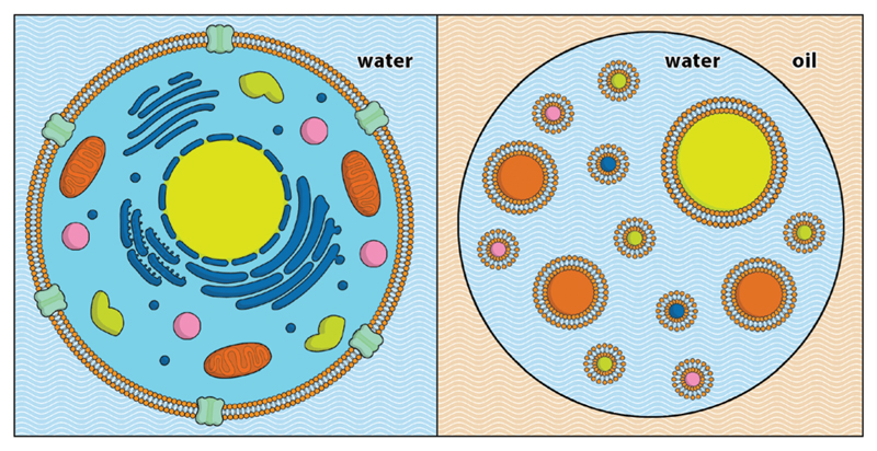
Based on the application of droplets to encapsulate prokaryotic and eukaryotic cells,31–36 we have developed a novel hybrid system that combines the ease of use and control of droplet microfluidics with the biological relevance of MVVs. Droplet-based microfluidics is used to encapsulate giant lipid vesicles inside aqueous droplets in a perfluorinated carrier phase to mimic the inner structure of cells and their organelles. Due to their structure analogy with MVVs, we refer to them as multivesicular droplets (MVDs) (Fig. 1). We show a microfluidic platform to generate MVDs and investigate biochemical reactions within them. MVDs can be trapped and analysed by bright field and fluorescence microscopy. We examine the integrity of lipid vesicles inside the MVDs during encapsulation and while being trapped in the array. Furthermore, we demonstrate the capability of the system to perform biochemical reactions with an enzyme cascade assay performed within the MVDs.
Fig. 1.
Schematic representation of a multivesicular droplet (MVD) (right), next to a eukaryotic cell (left). Droplet-based microfluidic techniques are used to encapsulate unilamellar lipid vesicles inside aqueous droplets, generating a hierarchical cell-like structure. Not to scale.
Experimental
Microfluidic chip design and operation
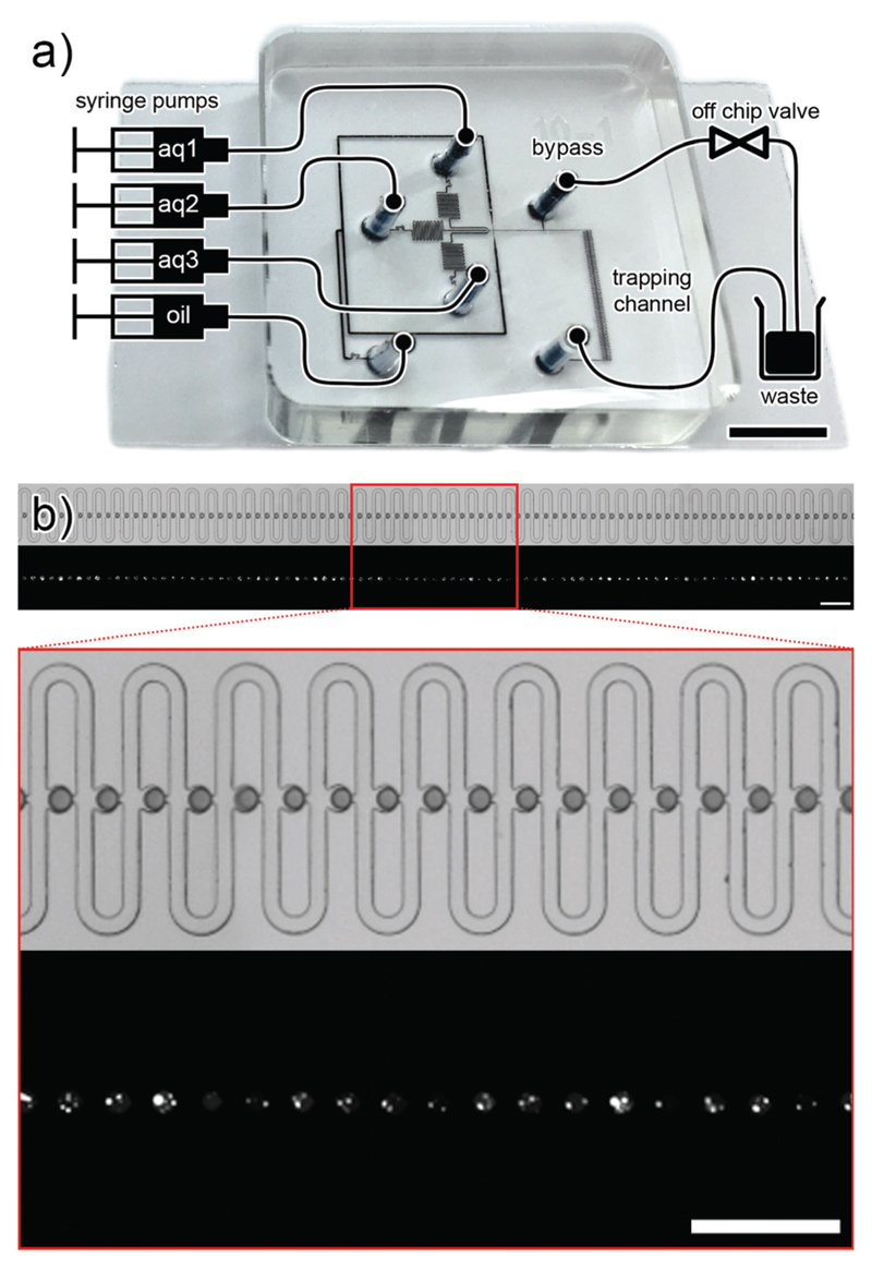
We have developed a microfluidic device to generate MVDs and trap them for further inspection (see Fig. 2a). The key component of this microfluidic chip design is the trapping array based on a design by Tan et al.37 and Shi et al.38 The trapping channel features 89 individual droplet traps with a diameter of 50 μm, which are able to trap droplets with diameters between 40–50 μm (see Fig. 2b). Each trap features a diversion channel with slightly higher hydrodynamic resistance than the trap. The droplet stream flows through the trapping channel until one droplet enters a trap. At the downstream side, the trap has a narrow opening that does not allow the droplet to pass. If the passage with the lowest resistance is blocked, all following droplets are redirected around the trap. This mechanism repeats until all the traps are occupied. Droplets can be flushed out from the trap by increasing the flow speed.
Fig. 2.
a) Scheme of the microfluidic chip setup (not to scale), overlaid on a picture of the chip, filled with black ink (scale bar: 5 mm). The setup comprises four syringe pumps which supply the aqueous (aq 1–3) and carrier phases (oil) to the chip. On-chip droplets are generated and trapped in a trapping array. Once the traps are filled with droplets, a bypass valve is opened to stop the flow of droplets through the trapping channel. b) Panoramic view and magnification of the 89-trap array. First row: bright field microscopy picture. The droplets are filled with blue food dye for better visualisation. Second row: fluorescence microscopy picture of the same array. The lipid vesicles are filled with fluorescent calcein. Scale bar: 250 μm.
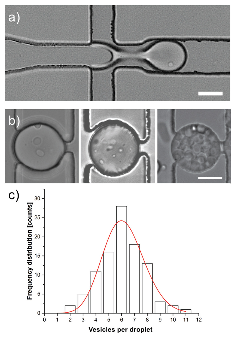
On-chip, up to three aqueous solutions can be used to generate droplets by flow focusing (see Fig. 3a). To provide a more precise control over the droplet flow interruption, a bypass channel with an external solenoid valve (Cetoni, Korbussen, Germany) was connected to the chip. The connection port for the valve is located on a side channel between the junction for droplet generation and the trapping array. As long as the valve is closed, the stream of droplets is directed to the trapping array. Opening the valve directs the droplet flow through the bypass and the flow of droplets through the trapping array stops immediately. Compared to a simple interruption of the flow in a straight channel, this design has the advantage to allow a much more precise control of the droplet location (see Fig. 2a and Video 1 in the ESI†).
Fig. 3.
a) Bright-field image of the lipid vesicle encapsulation. In the junction, the lipid vesicle suspension (left channel) and the carrier phase (top and bottom channel) are used to form droplets through flow-focusing. One lipid vesicle can be seen in the forming droplet as a bright dot. Scale bar: 25 μm. b) Bright field image of trapped MVDs produced using an increasing concentration of vesicle suspension showing an increment in the number of lipid vesicles per MVD. Scale bar: 25 μm. c) Frequency distribution histogram of the number of vesicles per droplet. To show the resemblance, a Poisson function was fitted and overlaid (red). The droplets (n = 100) were produced using flow rates of 0.5 μL min−1 of lipid vesicle suspension (medium concentration as described in the experimental section) and 3.0 μL min−1 of the carrier phase.
All fluids were supplied to the microfluidic chip through fluorinated ethylene propylene (FEP) tubing type 1548 from IDEX Health & Science (Washington, USA), from 1 ml BD Plastipak syringes (Heidelberg, Germany), with a neMESYS syringe pump (Cetoni, Korbussen, Germany). Typically, the flow rates of each of the aqueous phases and carrier phase were 0.25–1.0 μl min−1 and 2–4 μl min−1, respectively. See Fig. 2a) for a scheme of the microfluidic setup. All channels were fabricated with a height of 40 μm.
Chemical reagents
SU-8 2050 photoresist and mr-Dev 600 developer were obtained from Microchem Corp. (Massachusetts, USA) and Micro Resist Technology (Berlin, Germany), respectively. 1H,1H,2H,2H-Perfluorodecyltrichlorosilane and FC-40 were purchased from ABCR-Chemicals (Karlsruhe, Germany). The PDMS kit (Sylgard 184) was obtained from Dow Corning (Michigan, USA). The lipids 1-palmitoyl-2-oleoyl-sn-glycero-3-phosphocholine (POPC) and 1,2-distearoyl-sn-glycero-3-phosphoethanolamine-N-[biotinyl(polyethylene glycol)-2000] (ammonium salt) (DSPE-PEG(2000) biotin) were purchased from Avanti Polar Lipids (Alabama, USA). Alexa Fluor 488 streptavidin conjugate and DiI were obtained from Life Technologies (Oregon, USA). Mineral oil, chloroform, dimethyl sulfoxide (DMSO), glucose oxidase enzyme type VII (GOx), horseradish peroxidase type VI (HRP), Amplex Red, and Amplex Ultra Red were obtained from Thermo Fisher Scientific (Massachusetts, USA). Sodium phosphate, bovine serum albumin (BSA), methanol, d(+)-glucose, and d(+)-sucrose were purchased from Acros Organics (Geel, Belgium). The Alexa Fluor 488-conjugated AffiniPure goat anti-horseradish peroxidase antibody was obtained from Jackson Immuno Research Labs (Pennsylvania, USA). The biocompatible PFPE-PEG-PFPE triblock copolymer surfactant introduced by Holtze et al.39 was synthesised according to a protocol by Chen et al.40
Microfluidic chip fabrication
The master mould for the microfluidic chip was fabricated in a clean room. A standard 100 mm diameter silicon wafer (Si-Mat, Germany) was dehydrated for 10 min at 200 °C and after cooling down, it was spin coated with SU-8 2050 at 3250 rpm for 30 s. The photoresist layer was soft baked for 180 s at 65 °C and for 360 s at 95 °C before it was exposed to 160 mJ cm−2 at 365 nm through a transparency photomask (Micro Lithography Services, UK) on an MA 6 mask aligner (Süss MicroTec, Germany). After a post-exposure bake for 60 s at 65 °C and for 360 s at 95 °C, the wafer was developed using mr-Dev 600 developer for 5 min. The resulting features are 40 μm in height. As a final step, the wafer was placed in a 1H,1H,2H,2H-perfluorodecyltrichlorosilane atmosphere for 12 h at 100 mbar. This surface treatment is intended to facilitate the release of the PDMS cast from the wafer surface.
To fabricate the PDMS part of the microfluidic chip, the oligomer and curing agent were mixed together at a ratio of 10 : 1 and degassed afterwards. An aluminium casting mould was placed on the top of the wafer and the PDMS mix was poured to a height of 6 mm. After curing the PDMS on a hot plate for 8 min at 150 °C, it was cooled down and peeled off from the wafer. Fluid inlets and outlets were punched with a 1.5 mm outer diameter biopsy puncher (Miltex, PA, USA). The finished PDMS structure was bonded to a glass cover slip by exposure to air plasma using a PDC-32G plasma cleaner from Harrick Plasma (New York, USA). Prior to use, the channels on the chip were flushed for 15 min with a dry nitrogen stream carrying 1H,1H,2H,2H-perfluorodecyltrichlorosilane to ensure stable droplet generation and to prevent wetting of the channel walls by the aqueous phase.
Microscopy and data evaluation
Wide-field fluorescence microscopy experiments were performed using an Olympus IX71 inverted microscope (Tokyo, Japan) equipped with an iXon Ultra 897 EMCCD camera from Andor Technology (Belfast, Northern Ireland), mercury lamp as well as appropriate optical filter sets purchased from AHF Analysentechnik AG (Tübingen, Germany) for Alexa Fluor 488, (exciter HQ 470/40 X, dichroic 500 DCX, and emitter 500 LP), DiI (exciter D 535/50 X, dichroic 566 LP, and emitter 604 LP), Amplex Red (same filter set as DiI), Amplex Ultra Red (exciter 438/24, 509/22, dichroic 459/526/596 triple band, and emitter 475/543/702 HC triple filter), and antibody-conjugated Alexa Fluor 488 (dichroic 494 LP, and emitter 525/50 BrightLine HC). For bright-field microscopy, a UK1117 camera from EHD Imaging (Damme, Germany) and a Miro M110 high-speed camera (Vision Research, New Jersey, USA) were used. The recorded fluorescence signals were evaluated using ImageJ 10.2 (National Institute of Health, USA) and OriginPro 9.1 (OriginLab Corp., 241 Massachusetts, USA). The fluorescence intensities of the lipid vesicles (average fluorescence intensity over the whole area of the vesicle) were background corrected by subtracting the average fluorescence intensity of a location neighbouring the channel.
Solutions
All aqueous solutions were prepared in ultrahigh-purity water (Merck Millipore, Massachusetts, USA). The lipid vesicle medium is referred to as hosting solution (HS). The hosting and intravesicular solutions (IS) used in the DiI and streptavidin-labelling assays contained 1 Osm l−1 glucose and 1 Osm l−1 sucrose, respectively. The membrane labelling of the lipid vesicles was initiated by adding (on- or off-chip) either a solution of 13 μM DiI and 1 Osm l−1 glucose or a solution of Alexa Fluor 488 streptavidin conjugate (8 mg l−1) and 1 Osm l−1 glucose to the prepared lipid vesicle suspension (ratio 1 : 1).
The enzyme cascade assay required different solutions. The hosting solution contained 500 mOsm L−1 glucose and 50 mM sodium phosphate buffer (pH 7.4) and the intravesicular solution contained 500 mOsm l−1 sucrose, 50 mM sodium phosphate buffer (pH 7.4), 200 mU ml−1 HRP, and 0.06 mg ml−1 Alexa Fluor 488-conjugated AffiniPure goat anti-horseradish peroxidase antibody (for Fig. 5b) and c), a concentration of 2 mU ml−1 HRP was used instead). The enzyme cascade assay was conducted by adding (on- or off-chip) two different solutions to the prepared lipid vesicle suspension in a 1 : 1 : 1 ratio. The first solution contained 1 Osm l−1 glucose and either 0, 3, 15, 30, 50 or 150 μM Amplex Red. The second solution contained 15 mg l−1 BSA, 4 U mL−1 GOx, and 100 mM sodium phosphate buffer (pH 7.4).
Fig. 5.
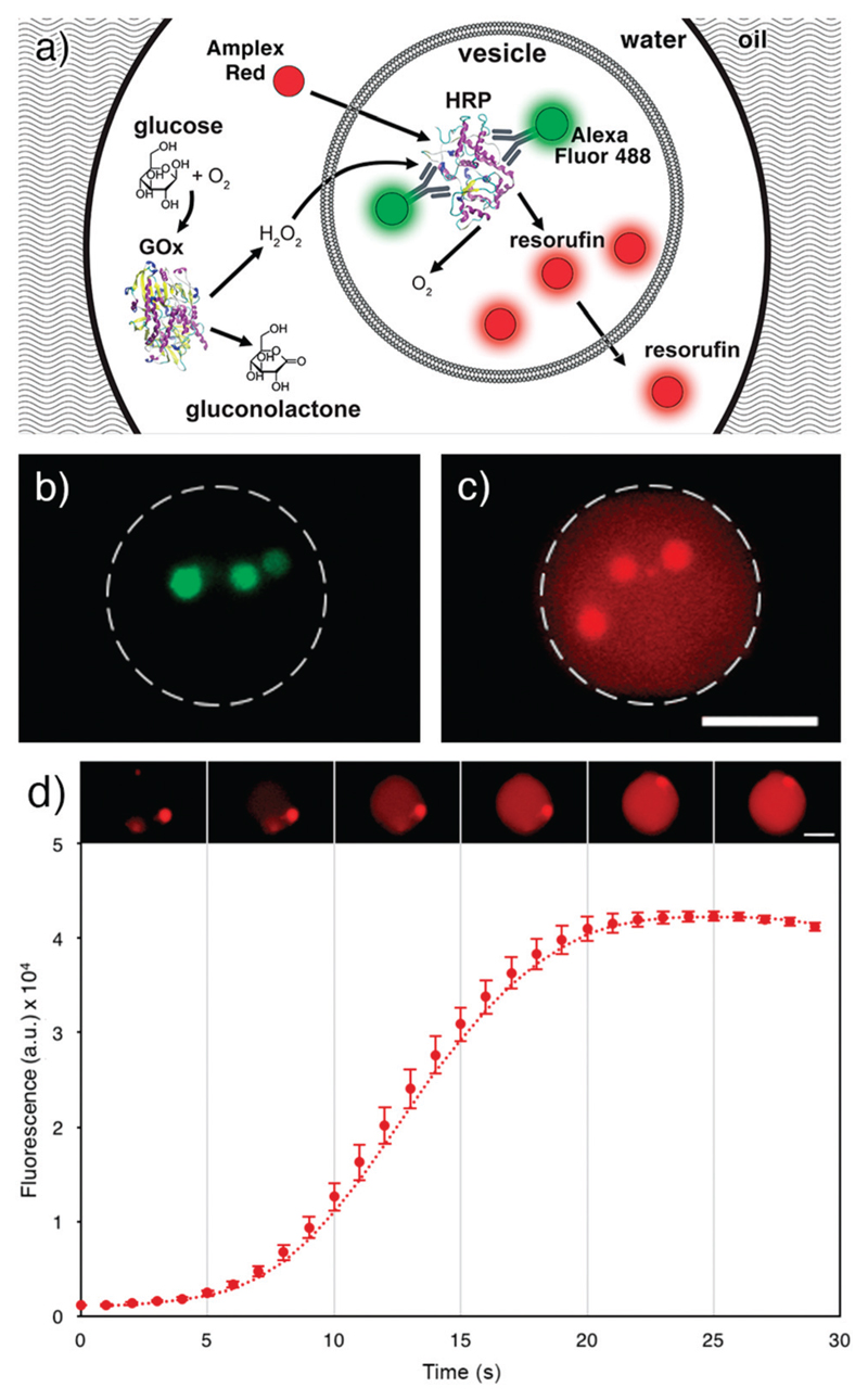
a) Scheme of the enzyme cascade assay in a MVD. Outside the lipid vesicle, GOx converts the substrate glucose to gluconolactone and hydrogen peroxide. Amplex Red and hydrogen peroxide permeate across the lipid bilayer into the lipid vesicle where the labelled HRP reacts with the two substrates to form oxygen and fluorescent resorufin. Resorufin is then diffusing out of the lipid vesicle, inside the droplet lumen (schematics is not to scale). b) Fluorescence image of Alexa Fluor 488 labelled HRP encapsulated in three lipid vesicles inside an MVD. c) Fluorescence image of the same MVD. The fluorescence originates from the resorufin generated in the enzyme cascade assay, and it is observed both in the lipid vesicles and in the droplet lumen. The initial Amplex Ultra Red concentration in the droplet pictured in b) and c) is 33 μM. Scale bar: 25 μm. d) Image sequence and plot of the mean pixel intensity of the entire MVD (n = 3). Error bars represent standard deviations.
For the enzyme cascade assay in Fig. 5b) and c), Amplex Ultra Red (100 μM) was used instead of Amplex Red. FC-40 containing 2 wt% biocompatible PFPE-PEG-PFPE triblock copolymer was used as the immiscible carrier phase for droplet generation. This solution was saturated with H2O by mixing and subsequently stored under a layer of water until use.
Giant lipid vesicle preparation
The giant unilamellar lipid vesicles were prepared by the water/oil emulsion transfer method.41 First, POPC and DSPE-PEG(2000) biotin, both dissolved in chloroform, were mixed at a molar ratio of 98 : 2. Subsequently, the chloroform was removed by vacuum evaporation and the dried lipids were dissolved again in mineral oil to a total phospholipid concentration of 200 μM. This phospholipid solution was sonicated for 60 min at 50 °C using a Sonorex Super sonicator (Bandelin, Berlin, Germany).
The following steps of the lipid vesicle preparation were performed in 1.5 ml polypropylene microtubes (Sarstedt, Nümbrecht, Germany). First, a water-in-oil emulsion of 50 μl of IS and 500 μl of phospholipid solution was produced by mechanical agitation. This emulsion was transferred to a microtube containing 500 μl of HS, layered with 200 μl of phospholipid solution. The droplets were forced through the interface between phospholipid solution and HS by centrifugation using a miniSpin plus centrifuge from Eppendorf (Hamburg, Germany) for 3 min at 4700 × g at room temperature. Lipid vesicles settle in a pellet at the bottom of the microtube. The supernatant was removed by aspiration, and the vesicle pellet was dissolved in 100 μl of HS and centrifuged again with the same settings. These washing steps were repeated three times before the lipid vesicles were dissolved in 50 μl of HS. The size of the resulting vesicles lies within the 2 and 30 μm range.
Results and discussion
Encapsulation process
The encapsulation of lipid vesicles in droplets requires careful selection of the carrier phase. Hydrophobic carrier phases like mineral oils are not suitable due to their ability to leach the phospholipids from the vesicles, which can lead to their rupturing. Therefore, we chose perfluorinated FC-40 containing 2 wt% biocompatible PFPE-PEG-PFPE triblock copolymer as our carrier phase.39 We produced monodisperse droplets in the size range of 45 to 50 μm by planar flow-focusing, using flow rates of 0.25–1 and 2–4 μl min−1 of the lipid vesicle suspension and carrier phase, respectively. We visualised the encapsulation process using high-speed bright-field microscopy (Fig. 3a, Video 2 in the ESI†) and adjusted the concentration of the lipid vesicle suspension to obtain 1–10 vesicles per droplet. In general, the number of vesicles per droplet followed a Poisson distribution (Fig. 3c). With a low concentration of the lipid vesicle suspension, MVDs containing mostly one or zero vesicles per droplet are formed (Fig. 3a). If the concentration of the lipid vesicle suspension is higher, the number of vesicles in the MVDs increases (Fig. 3b) and vesicles can fill the entire droplets without fusion.
Capturing of the MVDs
In order to inspect the lipid vesicles in a large number of droplets, we used the previously described trapping array to fix the MVDs in place. Thanks to the quick loading and unloading of the trapping array made possible by the described off-chip bypass valve, a cycle of droplet capture, analysis, and reloading with fresh droplets takes about 5–15 min, depending on the flow rate settings. This setup allows for quick batch-wise examinations of the MVDs by fluorescence microscopy (see Fig. S1†).
Depending on the flow rate settings, a low flow of the carrier phase through the array remains when the bypass valve is open (less than ~5% of the total flow). This causes the lipid vesicles to slowly rotate inside the droplets (see Video S3†). By stopping the droplet generation, this movement can be brought to a halt.
Moreover, the PDMS surface of the traps can dehydrate the droplets over time, causing them to shrink in size.42 To reduce this shrinkage, the PDMS chips were saturated with water before use. Nevertheless, the maximum time for which a MVD can typically be observed is 15 min (see Video S4†). After this time, the droplet becomes small enough that it is flushed out of the trap (~74% of the original diameter). For the assays in this study, which all take less than 1 min, this observation time is more than sufficient.
As we show further in this article, the carrier phase is not involved in the droplet shrinkage. Therefore, switching to a non-dehydrating material other than PDMS, e.g. glass, would allow for the long-term trapping and observation of slower reactions.
Lipid vesicle integrity
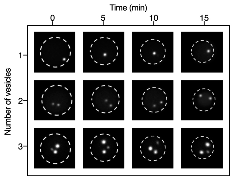
Since the formation of droplets by planar flow-focusing exposes the lipid vesicles to strong shear forces,43 their membrane might be damaged during the encapsulation process. To examine the vesicle integrity, two membrane staining processes were performed, and the membrane and lumen of the encapsulated vesicles were inspected while in the trapping array. First, the vesicles were incubated off-chip with either a solution containing the membrane dye DiI or Alexa Fluor 488 streptavidin conjugate which binds to the biotinylated phospholipids in the lipid vesicle membrane. After a washing step with the hosting solution, the labelled/stained vesicles were encapsulated in droplets and trapped in the array (see Fig. S2†). Both assays showed that the lipid vesicles remain intact. We also performed the labelling steps on-chip by supplying unlabelled lipid vesicle suspension and DiI solution through different inlet channels. The solutions were mixed within milliseconds inside the droplets,44 and DiI intercalated into the lipid vesicle membrane (Fig. S2c†). However, despite the fact that all channel walls were coated with perfluorosilane to reduce wetting by the aqueous phase, DiI adhered to the channel walls over the time course of the experiment, therefore on-chip staining is not recommended. For labelling procedures with highly water-soluble dyes such as the Alexa Flour 488-conjugated streptavidin solution, no leakage was observed (Fig. S2d†). In order to further prove that the lipid vesicles do not break or fuse with the droplet/carrier interface while the MVDs are trapped in the array, we counted the number of vesicles for each droplet immediately after trapping and after 5, 10, and 15 minutes by bright field microscopy. In all the droplets observed, the number of lipid vesicles remained the same (Fig. 4).
Fig. 4.
Images of MVDs containing one, two or three lipid vesicles at different time points. The vesicles contain fluorescent calcein, t = 0 is the moment of trapping in the array. We observed a total of 89 droplets for the maximum observation time. In all the MVDs observed, the number of lipid vesicles remained the same for the entire time.
Compartmentalised enzyme cascade reaction
After proving the stability of the lipid vesicles, we performed a two-step enzyme cascade reaction assay to demonstrate the capability of our setup to perform complex biochemical reactions inside MVDs. The first step of the reaction involved the conversion of glucose to gluconolactone and hydrogen peroxide in the droplet lumen by the enzyme glucose oxidase (GOx). The second step involved the conversion of Amplex Red to fluorescent resorufin in the lipid vesicle lumen by the enzyme horseradish peroxidase (HRP) in the presence of hydrogen peroxide (Fig. 5a).
To initiate the reaction cascade, we co-encapsulated and mixed in each droplet three different solutions containing: (i) glucose and Amplex Red, (ii) GOx, and (iii) a suspension of lipid vesicles filled with HRP. We have recently shown that HRP can be stably encapsulated in lipid vesicles without loss of activity.45 Here, HRP was bound with an Alexa Fluor 488-conjugated polyclonal goat anti-HRP antibody to visualise the encapsulation inside the inner lipid vesicles (Fig. 5b).
We investigated the resorufin fluorescence signal in the droplets from the moment of trapping (Fig. 5d), observing an immediate rise of fluorescence intensity within the lipid vesicles, confirming that resorufin is formed inside them.
We also observed a gradual fluorescence increase in the droplet lumen, indicating that not only Amplex Red and hydrogen peroxide, but also resorufin slowly permeate the lipid membrane, as presumed in a work by Grotzky et al.46 (see Fig. 5c). After about 25 seconds, resorufin fluorescence peaks and no new resorufin is produced. It should be noted that the concentration of the enzyme HRP is decreased here to 200 mU ml−1 to monitor the reaction. For higher concentrations, the reaction already terminated when the droplets are trapped, i.e., ca. 80 ms after formation.
After conversion of Amplex Red, the signal does not increase further but decreases due to photobleaching as the droplets are constantly exposed to light (see Fig. S3†). To quantify the leakage of resorufin in oil, we imaged resorufin-filled droplets in oil in a PDMS-free glass chamber. The droplets did not show any significant fluorescence intensity or size variation over one hour (Fig. S4†).
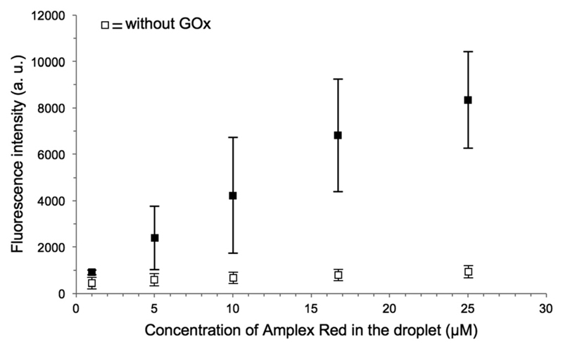
Finally, the fluorescence intensity inside the lipid vesicles was recorded for varying Amplex Red concentrations. MVDs with different concentrations of Amplex Red were generated, and the fluorescence intensity of the lumen of vesicles with sizes between 3 to 6 μm was measured immediately after trapping. As can be seen in Fig. 6, the fluorescence intensity of the lipid vesicles increases proportionally to the initial concentration of Amplex Red, as can be expected from the fast reaction, where the substrate conversion is completed. If a component is missing, e.g. GOx, the fluorescence intensity remains at the background level.
Fig. 6.
Graph showing the fluorescence intensities of the lipid vesicles plotted against the Amplex Red concentration in the droplet. All sample images were taken with the same acquisition setting, immediately after the droplet trapping (n = 8).
Conclusions
In conclusion, we introduced a microfluidic method for the generation of a novel droplet-based artificial cell model, and we optimised this method for the kinetic analysis of a two-step enzymatic cascade. In vitro, enzyme studies are often performed in a well-defined bulk aqueous solution. However, this setup does not reflect the environmental complexity in which the enzyme would perform in vivo.47 In live cells, enzyme-catalysed reactions occur in a molecularly crowded environment48 and often in confined spaces.49 Our method replicates these characteristics by providing a confined space that mimics the cytoplasm and by crowding it with lipid structures that simulate the labyrinth of organelles that can be found in a live cell. Our technique provides control over the loading of each compartment, as well as the droplet lumen. Therefore, we believe that it could provide a robust platform for the simulation of metabolic pathways taking place across and between the organelles. Precise kinetic investigations are possible, as the compounds are mixed at the exact moment in which the droplets are created. Moreover, the presented droplet microfluidic technology is biocompatible39 and would allow live cells to be co-encapsulated with lipid vesicles inside a droplet. Further work will be focused on the communication between compartments and the insertion of membrane transport proteins and pores for the exchange of metabolic and signalling molecules. We believe that our on-chip technology could ultimately aid synthetic cell research by providing a simplified, easy to use cell model of well-defined size and content.
Supplementary Material
† Electronic supplementary information (ESI) available. See DOI: 10.1039/c7lc00710h
Acknowledgements
We gratefully acknowledge funding from the European Research Council (ERC Consolidator grant no. 681587, HybCell). We also thank the clean room facility FIRST at ETH Zurich and V. Vogel (ETH Zurich) for providing the labelled streptavidin.
Footnotes
Conflicts of interest
There are no conflicts to declare.
References
- 1.Blain JC, Szostak JW. Annu Rev Biochem. 2014;83:615–640. doi: 10.1146/annurev-biochem-080411-124036. [DOI] [PubMed] [Google Scholar]
- 2.Adamala KP, Martin-Alarcon DA, Guthrie-Honea KR, Boyden ES. Nat Chem. 2016;9:431–439. doi: 10.1038/nchem.2644. [DOI] [PMC free article] [PubMed] [Google Scholar]
- 3.Walde P, Cosentino K, Engel H, Stano P. ChemBioChem. 2010;11:848–865. doi: 10.1002/cbic.201000010. [DOI] [PubMed] [Google Scholar]
- 4.Walde P. BioEssays. 2010;32:296–303. doi: 10.1002/bies.200900141. [DOI] [PubMed] [Google Scholar]
- 5.Khalifat N, Puff N, Bonneau S, Fournier J-B, Angelova MI. Biophys J. 2008;95:4924–4933. doi: 10.1529/biophysj.108.136077. [DOI] [PMC free article] [PubMed] [Google Scholar]
- 6.Ewers H, Römer W, Smith AE, Bacia K, Dmitrieff S, Chai W, Mancini R, Kartenbeck J, Chambon V, Berland L, Oppenheim A, et al. Nat Cell Biol. 2010;12:11–18. doi: 10.1038/ncb1999. [DOI] [PubMed] [Google Scholar]
- 7.Robinson T, Verboket PE, Eyer K, Dittrich PS. Lab Chip. 2014;14:2852. doi: 10.1039/c4lc00460d. [DOI] [PubMed] [Google Scholar]
- 8.Nomura SM, Tsumoto K, Hamada T, Akiyoshi K, Nakatani Y, Yoshikawa K. ChemBioChem. 2003;4:1172–1175. doi: 10.1002/cbic.200300630. [DOI] [PubMed] [Google Scholar]
- 9.Kim S, Turker MS, Chi EY, Sela S, Martin GM. Biochim Biophys Acta Biomembr. 1983;728:339–348. doi: 10.1016/0005-2736(83)90504-7. [DOI] [PubMed] [Google Scholar]
- 10.Kulkarni SB, Singh M, Betageri GV. J Pharm Pharmacol. 1997;49:491–495. doi: 10.1111/j.2042-7158.1997.tb06829.x. [DOI] [PubMed] [Google Scholar]
- 11.Zhang H, Wang G, Yang H. Expert Opin Drug Delivery. 2011;8:171–190. doi: 10.1517/17425247.2011.547470. [DOI] [PubMed] [Google Scholar]
- 12.Boyer C, Zasadzinski JA. ACS Nano. 2007;1:176–182. doi: 10.1021/nn7002025. [DOI] [PMC free article] [PubMed] [Google Scholar]
- 13.Bolinger P-Y, Stamou D, Vogel H. J Am Chem Soc. 2004;126:8594–8595. doi: 10.1021/ja049023u. [DOI] [PubMed] [Google Scholar]
- 14.Elani Y, Gee A, Law RV, Ces O. Chem Sci. 2013;4:3332–3338. [Google Scholar]
- 15.Elani Y, Law RV, Ces O. Nat Commun. 2014;5:5305. doi: 10.1038/ncomms6305. [DOI] [PubMed] [Google Scholar]
- 16.Elani Y, Law RV, Ces O. Phys Chem Chem Phys. 2015;17:15534–15537. doi: 10.1039/c4cp05933f. [DOI] [PubMed] [Google Scholar]
- 17.Okumura Y, Ohmiya T, Yamazaki T. Membranes. 2011;1:265–274. doi: 10.3390/membranes1040265. [DOI] [PMC free article] [PubMed] [Google Scholar]
- 18.Okumura Y, Nakaya T, Namai H, Urita K. Langmuir. 2011;27:3279–3282. doi: 10.1021/la2004485. [DOI] [PubMed] [Google Scholar]
- 19.Menger F, Lee S, Keiper J. Langmuir. 1996;12:4479–4480. [Google Scholar]
- 20.Walker SA, Kennedy MT, Zasadzinski JAN. Nature. 1997;387:61–64. doi: 10.1038/387061a0. [DOI] [PubMed] [Google Scholar]
- 21.Ahl PL, Perkins WR. Methods Enzymol. 2003;367:80–98. doi: 10.1016/S0076-6879(03)67007-2. [DOI] [PubMed] [Google Scholar]
- 22.Deng N-N, Yelleswarapu M, Zheng L, Huck WTS. J Am Chem Soc. 2017;139:587–590. doi: 10.1021/jacs.6b10977. [DOI] [PubMed] [Google Scholar]
- 23.Katayama K, Kato Y, Onishi H, Nagai T, Machida Y. Int J Pharm. 2002;248:93–99. doi: 10.1016/s0378-5173(02)00427-1. [DOI] [PubMed] [Google Scholar]
- 24.Yamabe K, Kato Y, Onishi H, Machida Y. J Controlled Release. 2003;90:71–79. doi: 10.1016/s0168-3659(03)00159-7. [DOI] [PubMed] [Google Scholar]
- 25.Zawada ZH. Cell Mol Biol Lett. 2004;9:589–602. [PubMed] [Google Scholar]
- 26.Teh S-Y, Lin R, Hung L-H, Lee AP. Lab Chip. 2008;8:198–220. doi: 10.1039/b715524g. [DOI] [PubMed] [Google Scholar]
- 27.Song H, Chen DL, Ismagilov RF. Angew Chem, Int Ed. 2006;45:7336–7356. doi: 10.1002/anie.200601554. [DOI] [PMC free article] [PubMed] [Google Scholar]
- 28.Dittrich PS, Jahnz M, Schwille P. ChemBioChem. 2005;6:811–814. doi: 10.1002/cbic.200400321. [DOI] [PubMed] [Google Scholar]
- 29.Okushima S, Nisisako T, Torii T, Higuchi T. Langmuir. 2004;20:9905–9908. doi: 10.1021/la0480336. [DOI] [PubMed] [Google Scholar]
- 30.Wang J-T, Wang J, Han J-J. Small. 2011;7:1728–1754. doi: 10.1002/smll.201001913. [DOI] [PubMed] [Google Scholar]
- 31.Martin K, Henkel T, Baier V, Grodrian A, Schön T, Roth M, Michael Köhler J, Metze J. Lab Chip. 2003;3:202–207. doi: 10.1039/b301258c. [DOI] [PubMed] [Google Scholar]
- 32.Sakai S, Kawabata K, Ono T, Ijima H, Kawakami K. Biomaterials. 2005;26:4786–4792. doi: 10.1016/j.biomaterials.2004.11.043. [DOI] [PubMed] [Google Scholar]
- 33.Oh H-J, Kim S-H, Baek J-Y, Seong G-H, Lee S-H. J Micromech Microeng. 2006;16:285–291. [Google Scholar]
- 34.Huebner A, Srisa-Art M, Holt D, Abell C, Hollfelder F, DeMello AJ, Edel JB. Chem Commun. 2007:1218. doi: 10.1039/b618570c. [DOI] [PubMed] [Google Scholar]
- 35.Grodrian A, Metze J, Henkel T, Martin K, Roth M, Köhler JM. Biosens Bioelectron. 2004;19:1421–1428. doi: 10.1016/j.bios.2003.12.021. [DOI] [PubMed] [Google Scholar]
- 36.He M, Edgar JS, Jeffries GDM, Lorenz RM, Shelby JP, Chiu DT. Anal Chem. 2005;77:1539–1544. doi: 10.1021/ac0480850. [DOI] [PubMed] [Google Scholar]
- 37.Tan W-H, Takeuchi S. Proc Natl Acad Sci U S A. 2007;104:1146–1151. doi: 10.1073/pnas.0606625104. [DOI] [PMC free article] [PubMed] [Google Scholar]
- 38.Shi W, Qin J, Ye N, Lin B. Lab Chip. 2008;8:1432. doi: 10.1039/b808753a. [DOI] [PubMed] [Google Scholar]
- 39.Holtze C. Lab Chip. 2008;8:1589–1752. doi: 10.1039/b800001h. [DOI] [PubMed] [Google Scholar]
- 40.Chen CH, Sarkar A, Song YA, Miller MA, Kim SJ, Griffith LG, Lauffenburger DA, Han J. J Am Chem Soc. 2011;133:10368–10371. doi: 10.1021/ja2036628. [DOI] [PMC free article] [PubMed] [Google Scholar]
- 41.Pautot S, Frisken BJ, Weitz DA. Langmuir. 2003;19:2870–2879. doi: 10.1073/pnas.1931005100. [DOI] [PMC free article] [PubMed] [Google Scholar]
- 42.Shim J-U, Cristobal G, Link DR, Thorsen T, Jia Y, Piattelli K, Fraden S. J Am Chem Soc. 2007;129:8825–8835. doi: 10.1021/ja071820f. [DOI] [PMC free article] [PubMed] [Google Scholar]
- 43.Anna SL, Bontoux N, Stone HA. Appl Phys Lett. 2003;82:364–366. [Google Scholar]
- 44.Bringer MR, Gerdts CJ, Song H, Tice JD, Ismagilov RF. Philos Trans R Soc A. 2004;362:1087–1104. doi: 10.1098/rsta.2003.1364. [DOI] [PMC free article] [PubMed] [Google Scholar]
- 45.Zhang Y, Schmid YRF, Luginbühl S, Wang Q, Dittrich PS, Walde P. Anal Chem. 2017;89:5484–5493. doi: 10.1021/acs.analchem.7b00423. [DOI] [PMC free article] [PubMed] [Google Scholar]
- 46.Grotzky A, Altamura E, Adamcik J, Carrara P, Stano P, Mavelli F, Nauser T, Mezzenga R, Schlüter AD, Walde P. Langmuir. 2013;29:10831–10840. doi: 10.1021/la401867c. [DOI] [PubMed] [Google Scholar]
- 47.Küchler A, Yoshimoto M, Luginbühl S, Mavelli F, Walde P. Nat Nanotechnol. 2016;11:409–420. doi: 10.1038/nnano.2016.54. [DOI] [PubMed] [Google Scholar]
- 48.Ellis RJ. Trends Biochem Sci. 2001;26:597–604. doi: 10.1016/s0968-0004(01)01938-7. [DOI] [PubMed] [Google Scholar]
- 49.Conrado RJ, Varner JD, DeLisa MP. Curr Opin Biotechnol. 2008;19:492–499. doi: 10.1016/j.copbio.2008.07.006. [DOI] [PubMed] [Google Scholar]
Associated Data
This section collects any data citations, data availability statements, or supplementary materials included in this article.


