Abstract
This paper presents the mechatronic design and experimental validation of a novel powered knee-ankle orthosis for testing torque-driven rehabilitation control strategies. The modular actuator of the orthosis is designed with a torque dense motor and a custom low-ratio transmission (24:1) to provide mechanical transparency to the user, allowing them to actively contribute to their joint kinematics during gait training. The 4.88 kg orthosis utilizes frameless components and light materials, such as aluminum alloy and carbon fiber, to reduce its mass. A human subject experiment demonstrates accurate torque control with high output torque during stance and low backdrive torque during swing at fast walking speeds. This work shows that backdrivability, precise torque control, high torque output, and light weight can be achieved in a powered orthosis without the high cost and complexity of variable transmissions, clutches, and/or series elastic components.
I. INTRODUCTION
Physical training is often needed for patients to relearn how to walk after a stroke [1]–[3]. However, the frequency and availability of physical training are limited by finite medical resources. To address this, researchers are investigating powered lower-limb rehabilitation orthoses to relieve the repetitive and physically tasking duties of therapists as well as to improve patient recovery efficacy [4]. Currently, most lower-limb rehabilitation orthoses are stationary and only available in a small number of hospitals, due to high cost and large size. A personal mobile lower-limb orthosis that can be used in the clinic or at home is desirable for different rehabilitation purposes [5].
Due to the high torque requirements of lower-limb joints, past research has focused on increasing the torque density of powered orthoses to provide enough output torque within an acceptable weight. Consequently, the combination of a highspeed motor and a high-ratio transmission, e.g., ball screw or harmonic drive, is common in powered lower-limb orthoses [6]–[11]. However, the use of a high-ratio transmission results in high mechanical impedance, which means that the user cannot move their joints without help from the orthosis. An orthosis is said to be backdrivable if users can drive their joints without a high resistive torque from the orthosis. Backdrivability may not be necessary for patients who cannot contribute to their walking gait, e.g., patients with spinal cord injuries. For patients who still have some control of their legs, a backdrivable orthosis can promote user participation and provide comfort during physical therapy. In particular, a mobile powered lower-limb orthosis for stroke rehabilitation purposes should be as mechanically transparent as possible.
In addition, advanced torque control methods for emerging physical therapies (e.g., [12]–[16]) require the orthosis to accurately control its torque output during locomotion [17]. Series Elastic Actuators (SEA) have been widely researched [18] and applied in mobile orthoses to address the above two requirements: backdrivability and torque control [19]–[23]. In particular, a torque control system can be implemented by measuring the displacement of elastic components. Active backdrivability can then be achieved by servoing the spring displacement to zero. However, current orthoses with SEA suffer from various limitations, such as low output torque [19], [20], complex system architecture [22], [24], bulky size [23], or limited force/torque control bandwidth [20], [25].
This paper presents the design of a novel powered knee-ankle orthosis that achieves 1) high output torque without a high-ratio transmission and 2) precise torque control and backdrivability without series elastic components. To eliminate the need for a high-ratio transmission, the presented orthosis uses a high torque density electrical motor. A distributed low-ratio transmission is designed to reduce the mechanical impedance and allow the user to easily move their joints. The compact, lightweight actuator provides enough torque and power output to assist the knee and ankle joints during human locomotion. In particular, the orthosis can achieve a continuous output torque of 30 Nm (and 60 Nm peak torque) at each joint during normal walking speeds. Each actuator weighs less than 1.2 kg and thus has a higher torque density than previous low-ratio orthosis actuators [26], [27]. A closed-loop torque control system with a reaction torque sensor can precisely achieve assistive or resistive torques for different physical therapies.
Although high torque output and backdrivability are typically considered tradeoffs in wearable robots, the presented orthosis successfully balances the core requirements of rehabilitation training: backdrivability, torque control, high torque density, and light weight. Our experimental results demonstrate that high torque output during stance phase and low backdrive torque during swing phase can be achieved without using a clutch [28] or variable transmission [29]. Instead of increasing the ratio of the transmission as in previous designs, the presented orthosis achieves a high output torque by increasing the torque density of the electrical motor. This work demonstrates that the core requirements of a powered orthosis can be met with a nearly direct drive actuation system, which has several advantages in the context of legged locomotion [30]. In particular, the custom low-ratio transmission of the presented orthosis provides intrinsic backdrivability without the cost and complexity of variable transmissions, clutches, and/or series elastic components.
The designs of the actuation, torque control, and feedback systems are presented in Section 2. Several experiments are presented to verify key features for the orthosis system in Section 3. Concluding remarks are given in Section 4.
II. Design of Orthosis System
This section presents the design of the powered unilateral lower-limb orthosis, including the actuation system, electrical system, and torque control system. A photo and rendering of the overall system are shown in Fig. 1. The ankle and knee are actuated to dynamically offload body weight from the affected leg of a stroke patient as proposed in [12]. The two actuator modules are attached to a knee-ankle-foot orthotic brace to drive the knee and ankle joints. Torque is transferred to the human ankle through a carbon fiber shoe insert. Several sensors are installed on the brace and the actuator modules to monitor key variables of the gait cycle. A block diagram for the whole orthosis system is shown in Fig. 2. The different systems are described below.
Fig. 1.
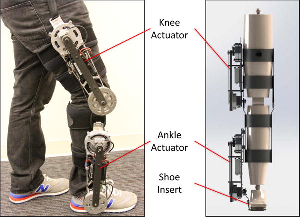
Orthosis System: Two modular actuators are attached to a knee brace and provide torque to the knee and ankle joints of the affected leg.
Fig. 2.
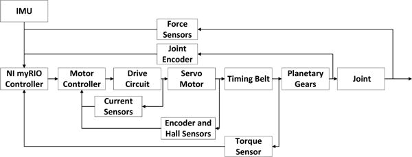
Schematic of the Powered Orthosis System: A servo motor generates a torque, which is then amplified by a timing belt and a planetary gear transmission. A orthosis control system is built with a myRIO controller and a motor controller.
A. Actuation System Design
To provide a sufficient torque output for gait training, the actuation system is designed to generate 30% of the torque and power of healthy human joints during level-ground walking according to previously reported data [31]. The targeted requirements are shown in Fig. 3. To avoid using a high-ratio transmission, the motor needs to generate higher torque. A high torque density PMSM (i.e., AC servo motor) is used to provide sufficient input torque and power to the transmission. By optimizing the motor winding configuration, the custom motor (MF0096008, Allied Motion, Inc.) can produce 7.2 Nm peak torque and 200 W power. The PMSM has distributed windings to reduce the torque ripple and produce a smoother torque output [32].
Fig. 3.
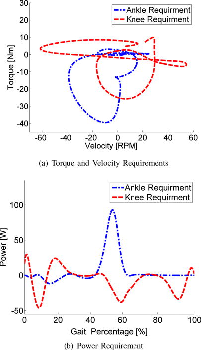
Requirements for the Powered Orthosis: 30% torque and power of healthy human joints over a complete gait cycle during level-ground walking.
A distributed two-stage low-ratio transmission is designed for the actuator. A poly chain GT carbon timing belt (3MR, ratio 4:1, Gates Industry, Inc.) is used to amplify the motor torque and to move the actuator weight closer to the user’s center of mass, which minimizes the metabolic burden of added weight during locomotion [33]. A custom 6:1 planetary gear transmission is built inside the driven sprocket of the timing belt to minimize weight and size. The overall ratio of the two-stage transmission is 24:1 with an estimated efficiency of 90%. The schematic of the actuator is shown in Fig. 4.
Fig. 4.
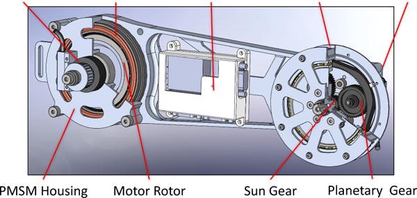
Schematic of Actuator: A frameless electrical motor is integrated with the mechanical structure of the presented orthosis. A timing belt connects the output shaft of the motor to the sun gear. A planetary gear set is built inside the driven sprocket. The actuator driver controls and drives the actuator.
This actuator design achieves the required torque output by increasing the torque density of the electrical motor rather than the ratio of the transmission. The reflected inertia is dramatically reduced by using the low-ratio transmission. Consequently, intrinsic backdrivability is achieved without any sensing or control. The combination of the torque dense motor and the distributed low-ratio transmission can produce 156 Nm output torque in theory. However, the motor’s torque is limited by a thermal condition, and the motor’s velocity output is limited by working voltage. To balance the torque and velocity requirements, the actuation system is designed to provide 30 Nm continuous torque output with peak velocity 80 RPM. The motor driver’s maximum current (30 A) and the mechanical structure limit the peak torque to 60 Nm.
The mechanical structure of the actuation system is mainly manufactured with aluminum alloy. Several carbon fiber mechanical pieces are used to reduce heavy metal material and enhance the strength of the actuation system. With the use of a frameless motor and a custom transmission, all core components are integrally designed with the mechanical structure to further reduce the weight of the orthosis. For instance, the motor housing is part of the main structure of the orthosis. The final weight of each actuation system is less than 1.2 kg. The orthosis weight specification is shown in Table I.
B. Electrical System Design
The electrical system of the lower-limb orthosis has two main parts: a high-level gait control system and a low-level actuator drive system. The gait control system monitors the key variables of the user’s gait to implement any given torque-based rehabilitation algorithm. The actuator drive system drives the actuator to track torque commands from the gait control system. The block diagram of the electrical system is shown in Fig. 5.
Fig. 5.
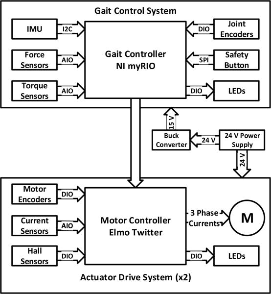
Block Diagram of Electrical System: The gait control system receives feedback related to the user’s gait and sends torque commands. The two actuator drive systems control and drive the knee and ankle actuators. A buck DC-DC converter provides power to the gait control system.
The gait control algorithm is implemented on a myRIO 1900 microcontroller (National Instruments, Inc.), which has a dual-core ARM microprocessor and a Xilinx FPGA. To achieve different torque based rehabilitation control algorithms, several features from the user’s gait cycle (e.g., gait phases and joint angles) are measured by the following sensors. The phase of gait, e.g., stance vs. swing, is detected with two force sensing resistors (FlexiForce A301, Tekscan, Inc.) embedded into a flexible insole, which is placed beneath the user’s foot in their shoe. These two force sensors are placed along the normal path of the center of pressure, with one under the heel and the other under the ball of the foot. The insole is printed from a rubber-like polyjet photopolymer by a Connex 350 3D printer. Two magnetic incremental encoders (6400 CPR, LM13, Renishaw, Inc.), which are located at the output shaft of the actuator, measure the ankle and knee angles. The components and I/O channels of the high-level gait control system are integrated through a custom Printed Circuit Board (PCB).
The actuator drive system is designed to precisely control each actuator. The PMSM is driven by a field oriented motor controller (G-TWI-25/100-SE, Elmo Motion Control, Ltd.), which has faster response time and less torque ripple compared to trapezoidal motor control [34]. Three hall-effect sensors (SS461A, Honeywell, Inc.) and a magnetic incremental encoder (6400 CPR, LM13, Renishaw, Inc.) are attached to the motor to obtain accurate absolute position feedback for the field oriented motor controller. A reaction torque sensor (M2210E, Sunrise Instruments Co., Ltd.) is installed at the output shaft of the actuator to measure the real torque output from the actuator. A custom low-level PCB for each joint integrates the I/O signals from sensors and motor drivers and communicates with the high-level PCB through a HD-15 cable. The following section describes how the actuator drive system controls the joint torque output.
C. Torque Control System Design
A common method for torque control is based on estimating the actuator’s output torque through the motor phase currents and the transmission ratio and efficiency. The electromagnetic motor torque Te and actuator output torque Ta are given by the following equation:
| (1) |
where P is the number of motor poles, λm is the motor flux linkage, Iq is the active current in the d-q rotating reference frame and is calculated by the Clark and the Park transformation [35], η is the transmission efficiency, and τ is the transmission ratio. Equation (1) determines the reference motor current to achieve the desired output torque, and the reference motor current is regulated by a proportional-integral (PI) control loop around the motor driver (the inner loop in Fig. 6).
Fig. 6.
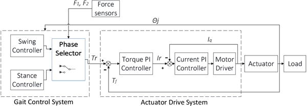
Torque control system schematic, where θj represents joint angles, F1 and F2 are ground reaction forces, Tr is torque reference, Tf is actuator torque output feedback, Ir is current reference, and Iq is motor active current [35]. The phase selector detects the stance and swing phase. The stance and swing controllers produce the torque reference. The actuator drive system contains two closed-loop PI controllers. The inner loop is the current PI controller which controls the motor’s current. The outer loop is the torque PI controller to compensate for the actuator’s torque error.
Typically, the transmission efficiency η is not constant during dynamic motion, causing inaccurate torque estimates from equation (1) and thus inaccurate actuator output torques. One of the potential benefits of low-ratio transmissions is a more constant transmissions efficiency for more accurate current-based torque control. For comparison, we also implemented a second (outer) torque control loop to compensate the torque error measured by the reaction torque sensor. Both loops (inner current loop and outer torque loop) use PI control to enforce the commanded torque. The control schematic is shown in Fig. 6.
D. Actuator Bandwidth Test
Before experimenting with human subjects, a closed-loop velocity bandwidth test of the actuation system’s dynamic performance was performed. Although the control objective may vary between different rehabilitation algorithms, actuator velocity is an important variable to evaluate system dynamic performance. In the closed-loop velocity bandwidth test, the motor was controlled by field oriented control over various frequencies, and the actuator’s output velocity was recorded. A simple PD velocity control loop was implemented through the motor controller. During this long experiment time, the motor was limited to its continuous working current of 10 A for safety reasons. The target velocity of the bandwidth test is set to 1000 RPM, which is a normal operating velocity during walking. The experiment results in Fig. 7 show that the actuator’s bandwidth frequency is 12 Hz, which is higher than that required for normal human walking (4–8 Hz) [31]. Fig. 7 is a conservative estimate based on the continuous current of the motor, and the bandwidth frequency would increase with peak current above 10 A.
Fig. 7.
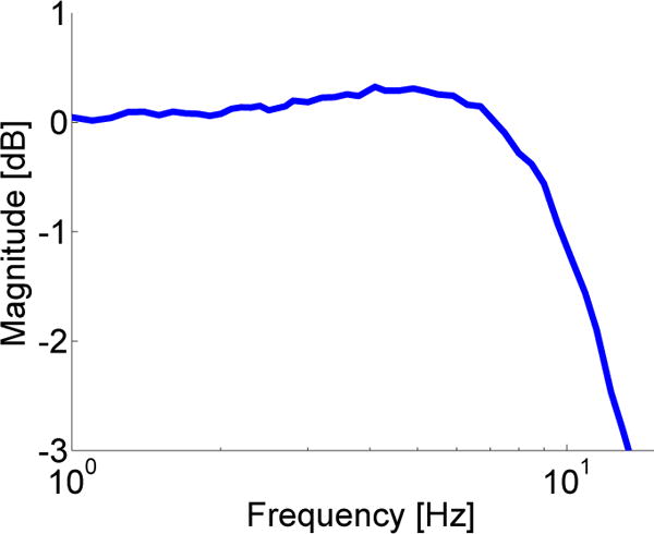
Magnitude of the Velocity Closed-loop Bandwidth: The frequency at −3 dB is 12 Hz, which shows that the presented orthosis has sufficiently fast dynamic performance for gait assistance.
III. Human Subject Experiments and Results
The orthosis design was validated in two experiments with a healthy human subject wearing the orthosis while walking on a treadmill. A passive walking test (i.e., zero command torque) was conducted to demonstrate both intrinsic and active backdrivability. A high torque walking test (using a high-level quasi-stiffness controller [36]) then demonstrated the output torque and power capabilities of the orthosis.
A. Experimental Setup
The experimental setup is shown in Fig. 8. The orthosis was attached to a knee brace and tightened with four flexible straps around the subject’s right leg. The subject wore a back brace which carried the gait control system. A strap connected the orthosis and the back brace to help suspend the weight of the orthosis.
Fig. 8.
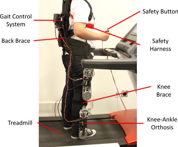
Human Subject Experiment Setup
The human subject experiment was approved by the Institutional Review Board of UT Dallas. A safety harness was attached to the subject’s torso to prevent falling. Additionally, a safety button was held in the subject’s hand during the experiments. If the button were to be released, the actuation drive system would be deactivated.
Passive and high torque walking tests were conducted with this experimental setup. The treadmill speed was set to 2.0 miles per hour (MPH) for passive walking test and 2.7 MPH for high torque tests, which is faster than a stroke patient’s normal walking speed. The faster walking speed was chosen to examine dynamic backdrive conditions and to demonstrate the high power capabilities of the device. Data was recorded once the subject reached a steady gait (after about 5 steps). A supplemental video recording is available for download.
B. Passive Walking Test
The command torque for both joints was set to zero for the passive walking test. The subject began this test with active torque compensation enabled, i.e., using the double-closed-loop torque controller. After several steps, the user released the safety button and deactivated the actuator. The torque sensor, located at the actuator’s output shaft, measured the torque between the human and the orthosis during walking on the treadmill. The backdrive torques with and without torque compensation are shown in Fig. 9. Each curve was calculated by the average absolute value of 10 steady steps before and after the button releasing moment. The shaded regions represent ±1 standard deviation about the mean.
Fig. 9.
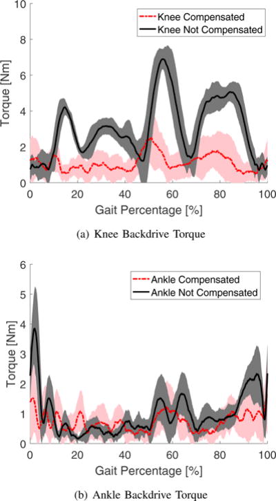
Measured Backdrive Torque during Passive Walking: Average absolute values and error bars (±1 standard deviation shown in shaded regions).
The amplitudes of the intrinsic backdrive torques were lower than 8 Nm. The peak backdrive torque of the ankle joint occurred during early stance, primarily due to heel contact. The ankle’s intrinsic backdrive torque during swing was only 2.5 Nm. The intrinsic backdrive torques would likely be smaller in a clinical application, where slower walking speeds are expected.
By using the double-closed-loop torque controller, the backdrive torques were further reduced. The mean value of the average absolute torque was reduced by 22.9% for the ankle joint and 63.13% for the knee joint. The peak backdrive torque was reduced by 57.87% for the ankle joint and 63.56% for the knee joint. Aside from the actuation system, misalignment of the orthosis brace and heel contact contributed to the remaining backdrive torque.
C. High Torque Walking Test
The high torque walking test aimed to validate the output torque and power capabilities of the orthosis. We adopted Quasi-Stiffness Control as an example control strategy, which implements a virtual spring at each joint based on the slope of the desired torque-angle curve for healthy human walking [36], [37]. Quasi-stiffness directly maps the measured joint angle to the command torque, providing a simple high-level controller for high torque testing. Quasi-stiffness determined the command torque during the stance period, whereas the reference torque was set to zero during swing to further validate backdrivability. To simplify implementation, we adopted the average of the knee quasi-stiffness values of the stance phase presented in [38] for the knee joint. Two different ankle quasi-stiffness values from [39] were used for the ankle joint. The control law is given by
If stance
If swing
where uknee and uankle denote the torque being applied at the knee and ankle joints, α = 0.3 denotes the 30% support ratio, θa and θk denote the relative angles for the ankle and knee joints, and Kk = 6.29 Nm · deg−1 is the quasi-stiffness value for the knee joint. An angular threshold was manually tuned to trigger the transition from ankle dorsiflexion with Ka1 = 6.53 Nm · deg−1 to plantar-flexion with Ka2 = 21.16 Nm•deg−1. The stance and swing transitions were detected using two force sensors located at the heel and toe part of the shoe insert. We defined ankle plantar-flexion and knee flexion as the positive angular directions. To guarantee safety and smooth transitions, we applied a fading process when switching between phases, i.e., using the weighted sum of the stance and swing torque laws.
We implemented two different low-level actuator drive modes with this high-level control strategy. The current control mode only used the inner current loop in Fig. 6 to control the actuator torque output. The second mode used the double-closed-loop torque controller in Fig. 6 to compensate the measured torque error. The parameters of the torque PI controller were manually tuned to minimize backdrive torque, whereas the current PI parameters were tuned to minimize response time. The ankle’s torque reference was set to zero at the beginning of each stance phase to avoid vibration from heel contact.
Before beginning the high torque test, the feedback for the two force sensors was calibrated for detecting the transitions between stance and swing. The angle feedback for all joints was initialized while the subject stood in a upright position. The mean and variance over 10 steady steps with both low-level actuator drive modes are shown in Fig. 10.
Fig. 10.
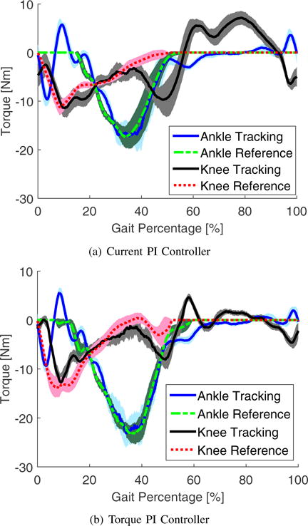
Torque Outputs of Normal Walking: Mean values (reference and tracking) and error bars (±1 standard deviation shown in shaded regions) of the actuator torque with quasi-stiffness control.
The orthosis produced high torque and power outputs at the selected walking speed. The peak value of the positive power and torque output reached 30 W and 27 Nm, respectively. The peak torque output of a single step was up to 30 Nm at the ankle. The demonstrated output torque and power could aid stroke patients in a variety of therapies and rehabilitation stages, including progressive walking speeds.
The peak ankle power (30 W) was lower than expected during late stance. By comparing with the passive walking case, we found that ankle dorsiflexion during early stance was reduced by the high extension torque command of the quasi-stiffness controller. The reduced ankle motion resulted in less power output. The performance of the orthosis will likely be improved in the future with more advanced torque-based control algorithms, e.g., potential energy shaping control [12].
The torque controller tracked the torque reference well during stance phase and swing phase. The current controller only tracked the torque reference accurately during stance phase, and had a large torque error during swing phase, which is shown in Fig. 10(a). The low-ratio transmission allowed an almost linear torque constant between the motor current and the actuator output torque. This allowed the current controller to estimate the actuator torque output accurately during stance phase. The torque error of the current controller during swing phase was mainly caused by the intrinsic backdrive torque. The performance of the current controller shows the possibility to implement a torque control system without using a torque sensor if the intrinsic backdrive torque can be further reduced in the mechanical design.
IV. CONCLUSION AND FUTURE WORK
This paper presented the design and validation of a light-weight, mobile, powered knee-ankle orthosis for gait rehabilitation training. By designing the orthosis with a torque dense motor and a low-ratio transmission, intrinsic backdrivability and high torque and power output are achieved with a simple structure. At the same time, the presented orthosis can maintain and track a high torque output at a high walking speed. These advantages affirm that the presented orthosis is a suitable platform for testing different rehabilitation control strategies.
Since the actuator is nearly a direct drive system, it demonstrates several advantages, such as improved dynamic performance, reduced intrinsic backdrive torque, and an almost linear torque constant. If intrinsic backdrive torque can be further decreased in the design, it will be possible to control the actuator’s output torque with motor current feedback instead of torque sensor feedback. This would allow the cost and weight of the torque sensors to be removed from the orthosis design.
Future work will involve implementing more advanced torque control algorithms such as [12] and performing experiments with patient subjects. Design improvements will be investigated to enhance the motor torque density and intrinsic backdrivability. A battery system with regenerative power electronics will also be added to the back brace for untethered operation of the orthosis.
Supplementary Material
TABLE I.
Orthosis Weight Specification
| Weight [kg] | |
|---|---|
| Actuators | 2.4 |
| Mechanical Structure | 1.12 |
| Attachment | 0.84 |
| Electrical System | 0.52 |
| Total Weight | 4.88 |
Acknowledgments
This work was supported by the National Institute of Child Health & Human Development of the NIH under Award Number DP2HD080349. The content is solely the responsibility of the authors and does not necessarily represent the official views of the NIH. R. D. Gregg holds a Career Award at the Scientific Interface from the Burroughs Welcome Fund. This work was also supported by the Eugene McDermott Graduate Fellowship.
References
- 1.Barbeau H, Norman K, Fung J, Visintin M, Ladouceur M. Does neurorehabilitation play a role in the recovery of walking in neurological populations? Annals of the New York Academy of Sciences. 1998;860(1):377–392. doi: 10.1111/j.1749-6632.1998.tb09063.x. [DOI] [PubMed] [Google Scholar]
- 2.Calautti C, Baron J-C. Functional neuroimaging studies of motor recovery after stroke in adults a review. Stroke. 2003;34(6):1553–1566. doi: 10.1161/01.STR.0000071761.36075.A6. [DOI] [PubMed] [Google Scholar]
- 3.Hesse S, Bertelt C, Jahnke M, Schaffrin A, Baake P, Malezic M, Mauritz K. Treadmill training with partial body weight support compared with physiotherapy in nonambulatory hemiparetic patients. Stroke. 1995;26(6):976–981. doi: 10.1161/01.str.26.6.976. [DOI] [PubMed] [Google Scholar]
- 4.Hidler J, Nichols D, Pelliccio M, Brady K, Campbell DD, Kahn JH, Hornby TG. Multicenter randomized clinical trial evaluating the effectiveness of the lokomat in subacute stroke. Neurorehabilitation and neural repair. 2009;23(1):5–13. doi: 10.1177/1545968308326632. [DOI] [PubMed] [Google Scholar]
- 5.Dollar AM, Herr H. Lower extremity exoskeletons and active orthoses: challenges and state-of-the-art. Robotics, IEEE Transactions on. 2008;24(1):144–158. [Google Scholar]
- 6.Pratt JE, Krupp BT, Morse CJ, Collins SH. Robotics and Automation, IEEE International Conference on. Vol. 3. IEEE; 2004. The roboknee: an exoskeleton for enhancing strength and endurance during walking; pp. 2430–2435. [Google Scholar]
- 7.Blaya JA, Herr H. Adaptive control of a variable-impedance ankle-foot orthosis to assist drop-foot gait. IEEE Trans Neural Systems and Rehabilitation Engineering. 2004;12(1):24–31. doi: 10.1109/TNSRE.2003.823266. [DOI] [PubMed] [Google Scholar]
- 8.Kawamoto H, Sankai Y. Power assist system hal-3 for gait disorder person. Computers helping people with special needs. 2002:19–29. [Google Scholar]
- 9.Aguilar-Sierra H, Lopez R, Yu W, Salazar S, Lozano R. A lower limb exoskeleton with hybrid actuation. inIEEE Int Conf Biomedical Robotics and Biomechatronics IEEE. 2014:695–700. [Google Scholar]
- 10.Lu R, Li Z, Su C-Y, Xue A. Development and learning control of a human limb with a rehabilitation exoskeleton. IEEE Trans Industrial Electronics. 2014;61(7):3776–3785. [Google Scholar]
- 11.Kiguchi K, Yokomine Y. Walking assist for a stroke survivor with a power-assist exoskeleton. IEEE Int Conf Systems, Man and Cybernetics IEEE. 2014:1888–1892. [Google Scholar]
- 12.Lv G, Gregg RD. Orthotic body-weight support through underactuated potential energy shaping with contact constraints. IEEE Conf Decision and Control IEEE. 2015:1483–1490. doi: 10.1109/cdc.2015.7402420. [DOI] [PMC free article] [PubMed] [Google Scholar]
- 13.Martin AE, Gregg RD. Hybrid invariance and stability of a feedback linearizing controller for powered prostheses. American Control Conference. 2015:4670–4676. doi: 10.1109/ACC.2015.7172065. [DOI] [PMC free article] [PubMed] [Google Scholar]
- 14.Quintero D, Villarreal DJ, Gregg RD. Preliminary experiments with a unified controller for a powered knee-ankle prosthetic leg across walking speeds. IEEE/RSJ Int Conf Intell Robots Syst. 2016 doi: 10.1109/IROS.2016.7759798. [DOI] [PMC free article] [PubMed] [Google Scholar]
- 15.Lv G, Gregg RD. Underactuated potential energy shaping with contact constraints: Application to a powered knee-ankle orthosis. IEEE Transactions on Control Systems Technology. 2017 doi: 10.1109/TCST.2016.2646319. [DOI] [PMC free article] [PubMed] [Google Scholar]
- 16.Lv G, Gregg RD. Towards total energy shaping control of lower-limb exoskele-tons. American Control Conference IEEE. 2017 doi: 10.23919/ACC.2017.7963706. [DOI] [PMC free article] [PubMed] [Google Scholar]
- 17.Lv G, Zhu H, Elery T, Li L, Gregg RD. Experimental implementation of underactuated potential energy shaping on a powered ankle-foot orthosis. IEEE International Conference on Robotics and Automation. 2016 May;:3493–3500. doi: 10.1109/ICRA.2016.7487529. [DOI] [PMC free article] [PubMed] [Google Scholar]
- 18.Paine N, Oh S, Sentis L. Design and control considerations for high-performance series elastic actuators. Mechatronics, IEEE/ASME Transactions on. 2014;19(3):1080–1091. [Google Scholar]
- 19.Kong K, Bae J, Tomizuka M. Control of rotary series elastic actuator for ideal force-mode actuation in human-robot interaction applications. Mechatronics, IEEE/ASME Transactions on. 2009;14(1):105–118. [Google Scholar]
- 20.Kong K, Bae J, Tomizuka M. A compact rotary series elastic actuator for human assistive systems. Mechatronics, IEEE/ASME Transactions on. 2012;17(2):288–297. [Google Scholar]
- 21.Accoto D, Carpino G, Sergi F, Tagliamonte NL, Zollo L, Guglielmelli E. Design and characterization of a novel high-power series elastic actuator for a lower limb robotic orthosis. International Journal of Advanced Robotic Systems. 2013;10 [Google Scholar]
- 22.Yu H, Cruz M Sta, Chen G, Huang S, Zhu C, Chew E, Ng YS, Thakor NV. Mechanical design of a portable knee-ankle-foot robot. Robotics and Automation, IEEE International Conference on IEEE. 2013:2183–2188. [Google Scholar]
- 23.Lagoda C, Schou AC, Stienen AH, Hekman EE, van der Kooij H. Design of an electric series elastic actuated joint for robotic gait rehabilitation training. IEEE Int Conf Biomedical Robotics and Biomechatronics IEEE. 2010:21–26. [Google Scholar]
- 24.Brackx B, Geeroms J, Vantilt J, Grosu V, Junius K, Cuypers H, Vanderborght B, Lefeber D. Design of a modular add-on compliant actuator to convert an orthosis into an assistive exoskeleton. IEEE Int Conf Biomedical Robotics and Biomechatronics IEEE. 2014:485–490. [Google Scholar]
- 25.Robinson DW. PhD dissertation, Massachusetts Institute of Technology. 2000. Design and analysis of series elasticity in closed-loop actuator force control. [Google Scholar]
- 26.Farris RJ, Quintero HA, Goldfarb M. Preliminary evaluation of a powered lower limb orthosis to aid walking in paraplegic individuals. IEEE Trans Neural Systems and Rehabilitation Engineering. 2011 Dec;19(6):652–659. doi: 10.1109/TNSRE.2011.2163083. [DOI] [PMC free article] [PubMed] [Google Scholar]
- 27.Quintero HA, Farris RJ, Goldfarb M. Control and implementation of a powered lower limb orthosis to aid walking in paraplegic individuals. IEEE International Conference on Rehabilitation Robotics. 2011 Jun;:1–6. doi: 10.1109/ICORR.2011.5975481. [DOI] [PMC free article] [PubMed] [Google Scholar]
- 28.Lenzi T, Sensinger J, Lipsey J, Hargrove L, Kuiken T. Design and preliminary testing of the RIC hybrid knee prosthesis. Int Conf IEEE Eng Medicine Biology Society. 2015 Aug;:1683–1686. doi: 10.1109/EMBC.2015.7318700. [DOI] [PubMed] [Google Scholar]
- 29.Shepherd M, Rouse E. Design and characterization of a torque-controllable actuator for knee assistance during sit-to-stand. Int Conf IEEE Eng Medicine Biology Society. 2016 doi: 10.1109/EMBC.2016.7591172. [DOI] [PubMed] [Google Scholar]
- 30.Kenneally G, De A, Koditschek D. Design principles for a family of direct-drive legged robots. IEEE Robotics and Automation Letters. 2016;1(2):900–907. [Google Scholar]
- 31.Winter DA. Biomechanics and Motor Control of Human Movement. 2nd. New York, NY: Wiley; 2009. [Google Scholar]
- 32.Jahns TM, Soong WL. Pulsating torque minimization techniques for permanent magnet ac motor drives-a review. Industrial Electronics, IEEE Transactions on. 1996;43(2):321–330. [Google Scholar]
- 33.Waters RL, Mulroy S. The energy expenditure of normal and pathologic gait. Gait & posture. 1999;9(3):207–231. doi: 10.1016/s0966-6362(99)00009-0. [DOI] [PubMed] [Google Scholar]
- 34.John JP, Kumar SS, Jaya B. Space vector modulation based field oriented control scheme for brushless dc motors. IEEE Int Conf Emerging Trends in Electrical and Computer Tech. 2011:346–351. [Google Scholar]
- 35.Krishnan R. Permanent magnet synchronous and brushless dc motor drives. 2010 [Google Scholar]
- 36.Shamaei K, Napolitano PC, Dollar AM. Design and functional evaluation of a quasi-passive compliant stance control knee—ankle—foot orthosis. IEEE Trans Neural Systems and Rehabilitation Engineering. 2014;22(2):258–68. doi: 10.1109/TNSRE.2014.2305664. [DOI] [PubMed] [Google Scholar]
- 37.Rouse EJ, Gregg RD, Hargrove LJ, Sensinger JW. The difference between stiffness and quasi-stiffness in the context of biomechanical modeling. IEEE Transactions on Biomedical Engineering. 2013;60(2):562–568. doi: 10.1109/TBME.2012.2230261. [DOI] [PMC free article] [PubMed] [Google Scholar]
- 38.Shamaei K, Sawicki GS, Dollar AM. Estimation of quasi-stiffness of the human knee in the stance phase of walking. PloS one. 2013;8(3):e59993. doi: 10.1371/journal.pone.0059993. [DOI] [PMC free article] [PubMed] [Google Scholar]
- 39.Shamaei K, Sawicki GS, Dollar AM. Estimation of quasi-stiffness and propulsive work of the human ankle in the stance phase of walking. PloS one. 2013;8(3):e59935. doi: 10.1371/journal.pone.0059935. [DOI] [PMC free article] [PubMed] [Google Scholar]
Associated Data
This section collects any data citations, data availability statements, or supplementary materials included in this article.


