Abstract
Alternating magnetic fields (AMFs) cause magnetic nanoparticles (MNPs) to dissipate heat while leaving surrounding tissue unharmed, a mechanism that serves as the basis for a variety of emerging biomedical technologies. Unfortunately, the challenges and costs of developing experimental setups commonly used to produce AMFs with suitable field amplitudes and frequencies present a barrier to researchers. This paper first presents a simple, cost-effective, and robust alternative for small AMF working volumes that uses soft ferromagnetic cores to focus the flux into a gap. As the experimental length scale increases to accommodate animal models (working volumes of 100s of cm3 or greater), poor thermal conductivity and volumetrically scaled core losses render that strategy ineffective. Comparatively feasible strategies for these larger volumes instead use low loss resonant tank circuits to generate circulating currents of 1 kA or greater in order to produce the comparable field amplitudes. These principles can be extended to the problem of identifying practical routes for scaling AMF setups to humans, an infrequently acknowledged challenge that influences the extent to which many applications of MNPs may ever become clinically relevant.
I. INTRODUCTION
Heat dissipated by magnetic nanoparticles (MNPs) plays a central mechanistic role in a variety of minimally invasive biomedical applications including cancer hyperthermia,1,2 site specific actuation of drug release,3,4 protein manipulation,5,6 and control over cellular functions, e.g., neural stimulation and insulin production.7–9 Research on these topics typically relies on externally applied alternating magnetic fields (AMFs) with amplitudes of tens of kA/m and frequencies of hundreds of kHz in order for the MNPs to generate sufficient hysteresis losses. The magnetic moments of MNPs offer a plausible energetic handle for actuation by AMFs of this amplitude,10 and experimental evidence has surprisingly indicated that nanoscale heating of MNPs is orders of magnitude greater than what macroscopic heat transport equations predict.11 Scrutiny of indiscriminate use of linear response theory, the predominant physical model used to describe MNP hysteresis in AMFs, has led to the development and experimental evaluation of more general models.12–17 These systems will likely continue to pose worthwhile fundamental questions and offer opportunities for applications in medicine and elsewhere.
One way to enable the scientific community in its ongoing study of these topics is to lower financial and technical barriers to the creation of experimental setups that produce AMFs. Laboratories conducting magnetic hyperthermia research often purchase induction furnaces or contract outside experts to make custom AMF setups,3,18 but these approaches can be prohibitively expensive. Simple, cost effective, and robustly functional alternatives exist,19,20 and this paper identifies and motivates several efficient strategies for creating suitable AMF-generating electromagnets and their driving circuits. An effective AMF electromagnet essentially functions as a low loss inductor, stably operating with uniform field amplitude in an accessible working volume. A small quantity of MNPs introduced into a sample, animal model, or patient are coupled to the circuit driving the inductor by the AMF, but even a highly efficient electromagnet dissipates several orders of magnitude more power in waste heat than it delivers to the MNPs. The benefit of AMFs in this context is not efficiency of power transfer by the circuit, but rather the targeted delivery of energy to MNPs that leaves surrounding tissue unharmed. The need to limit off-target power dissipation by weak eddy currents arising from the conductivity of tissue is typically stated in terms of a maximum allowable field amplitude-frequency product, H0 f. Time-averaged off-target power dissipation depends on many other factors including duty cycle, geometry of the exposed region, and field profile. Nevertheless, idealized eddy current power dissipation is a function of H0 f, so such a limit serves as a useful, if approximate, benchmark. Abiding by a frequently cited estimate of this physiological limit, H0 f ≤ 5 × 10⁹ Am−1 s−1,21 has the practical effect of limiting maximum useful operating frequencies to the low megahertz range for the purpose of heating MNPs in biomedical applications. At frequencies above this, the allowable amplitude diminishes more rapidly than the H0 f product suggests as conductivity of tissue increases, causing nonspecific power dissipation to increase.22
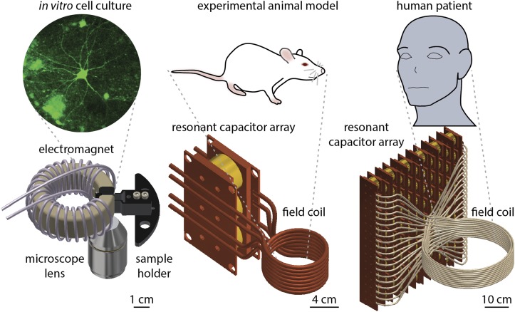
When designing an AMF setup for an experiment, the most crucial parameter to consider is scale; a feasible approach for producing a high amplitude field in a working volume of 1 cm3 cannot necessarily be scaled efficiently to 100 cm3 (Fig. 1). Unless practical methods can be identified to scale AMF setups producing the conditions represented in research to dimensions relevant to humans, many of the applications of MNPs currently being investigated may never leave the laboratory. This paper will begin by discussing AMF generation suitable for characterization of small samples, in vitro experimentation, and shallow targets in small animal models. It will then discuss the limitations of this approach in the context of large working volumes and demonstrate more appropriate designs, culminating in an analysis of human scale coils.
FIG. 1.
Generation of alternating magnetic fields at increasing length scales for biomedical research, progression of design strategies.
II. SMALL SCALE RESEARCH ELECTROMAGNETS: ∼2 cm3 WORKING VOLUME
A. Principle of operation for electromagnets with cores
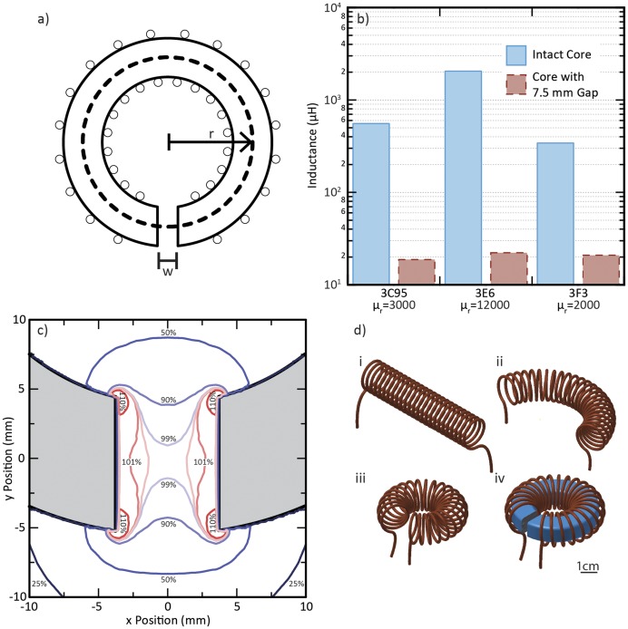
Electromagnets employing soft ferromagnetic cores magnetized by a current-carrying wire are commonplace in both laboratories and introductory physics textbooks.23 Regardless of the particular shape or size of the core, many of these instruments operate on the same physical principle by offering a high permeability path for magnetic flux with a comparatively small air gap that dominates the overall reluctance. To clarify how this leads to strong fields in the gap, consider a magnetostatic toroidal coil with a small gap of width w and N turns of a wire carrying a current I [Fig. 2(a)]. An Amperian loop around the circumference of a circular path of radius r that falls within the core relates the field to the current,
| (1) |
Here, Hg is the magnitude of the magnetic field in the gap and Hc is the magnitude of the field in the core, both assumed to be tangential and vary only with r. Magnetic flux is locally conserved, and in the limit of small gap width relative to the cross-sectional area of the core A, the fringing behavior of the field in the gap may be neglected such that a statement of flux conservation reads
| (2) |
| (3) |
Here, μ0 and μc are the permeability of free space and the core, respectively; Bg and Bc are the magnetic field in the gap and the core, respectively. This allows for the substitution
| (4) |
where relative permeability . Substituting Eq. (4) into Eq. (1) and solving for Hg yields
| (5) |
Because of the assumptions made in Eqs. (1) and (3), Eq. (5) provides an upper bound for the field in the gap. Its approximate form is justified in the limit of high relative permeability of the core and small but non-vanishing gap width. Even when the gap is widened somewhat, the same principle is still at work as demonstrated by the width of the gap dominating the inductive behavior of gapped toroids [Fig. 2(b)]. According to a planar magnetoquasistatic finite element model shown in Fig. 2(c), the field amplitude in the widened gap is predicted to remain reasonably uniform, with about 70% of the gap falling within ±5% of the mean value.
FIG. 2.
(a) Idealized gapped toroidal electromagnet geometry. (b) The influence of gap introduction on inductance for geometrically identical toroidal cores with 10 turns as measured experimentally using an LCR meter. Cores were manufactured by Ferroxcube, part numbers TX51/32/19-3C95, TX51/32/19-3E6, and TX51/32/19-3F3. (c) Detail of the gap region of a magnetostatic planar finite element model of electromagnet with a 7.5 mm gap and nonlinear B vs H manufacturer data for 3F3 at 25 °C. Magnetic field magnitude is shown relative to the mean magnetic field in the gap (25 kA/m) to assess uniformity. (d) A representation of an imagined deformation of a long solenoid into the windings of gapped toroidal electromagnet.
The advantage of this approach becomes evident when comparing it with the field of a long finite solenoid. The field Hs depends on the number of turns N and length L,
| (6) |
The enhancement of the field magnitude can be quantified by imagining that the long solenoid is deformed into the shape of a toroid acting as the windings of a gapped core while keeping N and I constant, as shown in Fig. 2(d),
Since the gap represents a small section of the circumference of the toroid, L/w would generally be much greater than 1. Despite relying on a few simplifying idealizations, this result demonstrates the utility of soft ferromagnetic flux paths for efficient generation of high magnetic fields. The use of a core allows the same field to be produced with lower current density and thus significantly lower power. For an electromagnet producing an AMF, the core will also generate losses that often far exceed the power dissipated in the wires, as discussed in Sec. III. However, for small working volumes and with appropriate core material selection, the same benefits apparent in the magnetostatic case can also be realized at frequencies approaching 1 MHz. The overall expense of an apparatus generating AMFs at this scale is dominated by the electronics powering it, so reducing the necessary power also reduces cost.
B. Practical implementation
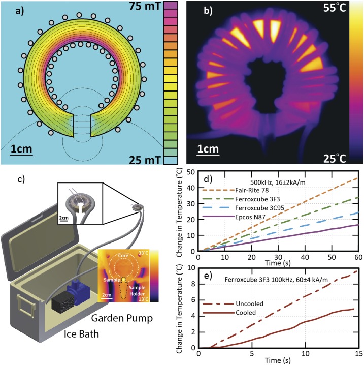
In the magnetostatic case, achievable field magnitudes in the gap can be limited by the saturation magnetization of the core material.24 At frequencies of hundreds of kHz, AMF amplitudes are more likely to be limited by core losses, either directly via increased effective resistance within the circuit or indirectly via the production of waste heat.19 These losses increase with flux density, and excessive heating can change the magnetic properties of the core or, worse yet, contaminate experimental results. This limitation is compounded by the fact that power ferrites, the best-performing core materials between 100 kHz and 1 MHz for this application, are poor thermal conductors. Consequently, significant heat can build up in the regions of highest flux [Figs. 3(a) and 3(b)]. For other applications at these frequencies, nanocrystalline materials and iron powder materials may offer viable alternatives, but the comparatively higher conductivity of these materials usually results in comparatively greater losses at the flux density amplitudes required for generating useful AMFs.
FIG. 3.
(a) Magnetostatic planar finite element model of flux distribution in the core of a 3F3 electromagnet (TX51/32/19) with a 7.5 mm gap and magnitude 16 kA/m at center of the gap. (b) Infrared thermograph of uncooled electromagnet operating with 16 kA/m gap amplitude at 500 kHz after 30 s. Note correlation of core temperature with flux density. (c) Sketch of low cost cooling apparatus with inset thermograph showing coil operating with cooling with gap amplitude 30 kA/m at 100 kHz. (d) Comparison of temperature versus time from infrared thermography on uncooled cores with 7.5 mm gaps operated at 500 kHz and 16 kA/m. (Part numbers: Ferroxcube TX51/32/19-3F3, Ferroxcube TX51/32/19-3C95, Epcos B64290L82X87, Fair-Rite 5978003801.) (e) Comparison of temperature increase of Ferroxcube TX51/32/19-3F3 with a 7.5 mm gap at 100 kHz and 60 kA/m with and without cooling.
Undesired heating can be mitigated through a combination of design and experimental practice. Small cores are favorable and active cooling (with water circulated from an ice bath) can help offset the dissipated heat as illustrated in Fig. 3(c). One simple approach is to immerse a garden pump with a filter in an ice chest and flow the water through silicone rubber tubing brought into thermal contact with the core of the electromagnet with electrically non-conducting thermal epoxy. Combined with a well-insulated sample holder, these electromagnets can be used for the measurement of MNP heating rates with low background. For some experimental setups, it may be advantageous to modify the geometry of the gap for a more uniform flux density distribution in the core, as discussed in the supplementary material.
Even among various ferrites intended for power magnetics, careful material selection can significantly reduce dissipated heat.25 Figure 3(d) compares temperature change in uncooled, similarly sized toroidal power ferrite cores produced by several manufacturers. Gaps were cut to the same width of 7.5 mm and the field in the gap was kept constant between trials. The cores were all wrapped with a single close-packed layer of litz wire (1050 strands of 44 AWG for a 2 mm overall diameter) protected with heat shrink tubing. Optimality of the core material depends on operating conditions, but for ferrites in the frequency range 100 kHz to 750 kHz, Ferroxcube’s 3F3 and Epcos’ N87 emerged as suitable options. Both materials are readily available in many geometries and heat acceptably at high flux densities [Fig. 3(e)]. Despite the measures taken to reduce heating, operation at the highest field amplitudes is typically limited to durations of tens of seconds punctuated by several minute rest periods.
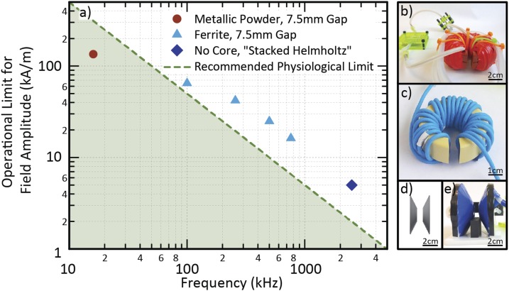
Figure 4(a) summarizes the maximum field amplitude used in standard operation as a function of frequency for several designs, as compared to the H0 f product clinical limit discussed earlier. For electromagnets based on metal powder cores, operation was limited to the low tens of kHz due to eddy current losses. Though falling below the H0 f limit, the electromagnet shown in Fig. 4(b) can reach amplitudes of up to 130 kA/m at 16 kHz. In the hundreds of kilohertz, power ferrite cores like the one shown in Fig. 4(c) can easily meet or exceed the limit. Although suitable ferrites for similar designs that operate near or above 1 MHz do exist25 and were tested up to 2.5 MHz, it was found that the benefits of using of a core diminish at these frequencies. The power savings realized by using a core relative to a coreless coil are reduced as the current required to reach the conditions suggested by the H0 f product limit decreases. If the two approaches require similar power dissipation to reach the target AMF amplitude, a litz wire design is favorable because it can transfer heat with its surroundings more effectively and is therefore more readily cooled.26 One such geometry that maintains the same field direction and homogeneity as the designs incorporating cores while reaching frequencies as high as 2.5 MHz is shown in Figs. 4(d) and 4(e). It employs a conical spiral of litz wire with a pitch of superimposed Helmholtz coils of increasing diameter held by a 3D printed wire guide and can optionally be cooled by a fan.
FIG. 4.
(a) Summary of normal operating conditions relative to one commonly stated H0 f product limit, 5 × 10⁹ A m−1 s−1. (b) Electromagnet for 16 kHz operation with two stacked Magnetics, Inc. MPP cores (part number C055866A2) with a 7.5 mm gap. (c) A Ferroxcube 3F3 ferrite core (TX51/32/19-3F3) with a 7.5 mm gap wrapped with insulated litz wire. (d) Sketch of wire geometry for a stacked Helmholtz coil. (e) Stacked Helmholtz coil incorporating 3D printed wire guides.
C. Drive circuit considerations
The circuits powering all of the AMF generation discussed in this paper make use of either series or parallel resonance, both of which store energy at their resonant frequency. In a series resonant circuit, a high voltage can build up between the capacitor and inductor, while the current in these elements is constrained (by definition) to the supplied current. In a parallel resonant circuit, a high circulating current can develop between the capacitor and inductor, while the voltage applied to the two elements is constrained (by definition) to the supplied voltage. Incorporating a core both increases inductive reactance and reduces the required current [Eq. (7)]; for a design with many turns of litz wire, this suggests the need for series rather than parallel resonance. The series resonant circuits used to drive electromagnets like those shown in Fig. 4 can build up thousands of volts between the capacitor and inductor at resonance, even with the modest currents on the order of 10 A necessary to achieve the desired field in the gap. This should be carefully considered for both user safety and setup durability—high voltage discharge through an uninsulated core and dielectric breakdown of the capacitors are both common modes of failure.19 Wherever possible, arrays of surface mounted high voltage mica capacitors with negligible equivalent series resistance may be used. The voltage that this array must be able to withstand Vw can be estimated by accounting for the current amplitude I0 required by Eq. (5), the resonance frequency fr, and the overall capacitance value C,
| (8) |
In some cases, it is desirable to mechanically isolate the interconnection between the inductor and capacitor from any circuit board in order to prevent dielectric breakdown through the board and mitigate any shunt capacitance to ground that could occur at that node.
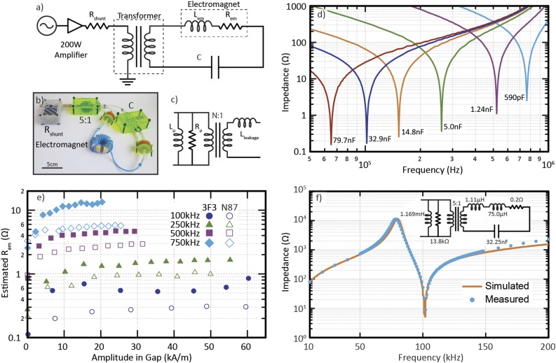
A circuit similar to the one shown by Lacroix et al.19 was used to step up the current supplied by a broadband amplifier designed for 50 Ω loads (E&I 1020L). A schematic with simplified nonideal component models is shown in Fig. 5(a), along with a representative photograph of the circuit in Fig. 5(b), and a nonideal transformer model in Fig. 5(c). Only a single capacitor array placed in the secondary is necessary to tune the resonance with the electromagnet, which has inductance Lem [Fig. 5(d)]. The effective resistance of the electromagnet Rem is dominated by the core loss and depends on both frequency and flux density. Figure 5(e) shows how Rem varies with frequency and field amplitude in the gap of a 3F3-based electromagnet, estimated by monitoring the voltage drop across the shunt resistor Rshunt.
FIG. 5.
(a) Simplified schematic for circuit driving AMF electromagnets with cores. (b) Photograph of a representative circuit. (c) Model of nonideal transformer. (d) Resonances of the same electromagnet placed in series with various capacitor arrays. (e) Estimated resistance of gapped toroidal electromagnets with 28 turns, comparable dimensions, and a 7.5 mm gap, as a function of magnetic field amplitude in the gap. Part numbers for cores: Ferroxcube TX51/32/19-3F3 and Epcos B64290L82X87. (f) Simulated low current impedance of a model based on measured component values is compared with impedance versus frequency measurements.
| (7) |
In a simplified model of a nonideal transformer [Fig. 5(c)], the leakage inductances from both sides can be lumped together as a single secondary-side inductance Lleakage; this represents the series inductance measured in the secondary circuit by an LCR meter when shorting the primary winding. (More precisely, this is a cantilever model of the transformer.27) Lleakage can shift the resonance frequency slightly, but it is significantly smaller than the inductance of an AMF electromagnet with the recommended design (e.g., ∼1 μH versus ∼75 μH). A parallel inductance Lμ, intended to model the magnetic energy and flux in the core of the transformer,28 is added to the primary circuit and can be estimated by measuring the series inductance of the primary windings with an open secondary circuit. Including this element in the model predicts a parallel resonance with the capacitor in the secondary circuit. If the transformer is made from an intact toroid of the same type used in the electromagnet, Lμ will generally be much larger than Lem [Fig. 2(b)], and its parallel resonance will occur at a frequency far below the series resonance of the secondary circuit. This simple transformer model, based on measured quantities, effectively captures the behavior of the circuit in Fig. 5(f) and makes the case for approximating the transformer as ideal in the vicinity of the series resonance where the AMF electromagnet operates.
III. LIMITS OF SCALABILITY
The scalability of inductors and transformers that incorporate soft ferromagnetic cores is a well-studied topic,29–31 typically focusing on figures of merit assessing storage and transfer of energy. A similar analysis can be conducted that considers the consequences of maintaining the same field amplitude in designs with and without cores as working volume increases. This constraint results in somewhat different design tradeoffs than with other goals. Since Sec. II A argued the utility of the designs with cores on the basis of a reduction in the power required to maintain a desired field amplitude, it is logical to first consider how this advantage is lost by increasing size.
Consider a coreless solenoid and an electromagnet with a core that are uniformly scaled up by a factor ε, while preserving the same field amplitude in the working volume. As will be discussed in Secs. IV–VI, scaled up designs usually favor a reduced number of turns, with less resistance per turn, so that this simple mental picture of enlarging a design with many turns is not entirely realistic. However, making such an assumption does not alter the most salient features of the analysis; both power dissipation and field amplitude can be seen as functionally dependent on distributions of flux density and current density. Maintaining the same number of turns while neglecting the effect on inductance is therefore a justifiable analytical expedient that approximates a scaled up distribution of current density.
The geometric dependence of the Biot-Savart law implies that to maintain the same field amplitude in a coreless coil, the new current Iε would need to increase by the factor ε,
| (9) |
Scaling also changes the original winding resistance R to a new value Rε. In direct current (DC) conditions or when properly-sized litz wire is used,32 the full cross sectional area of the wire is utilized, so scaling up the coil reduces its resistance, . Without litz wire, for a single-layer winding at high frequencies, the change in resistance may be estimated by assuming that the skin effect pushes current density fully to the outer surface of the wire. In this case, The actual exponent of the scaling factor for the resistance falls between these limiting cases, but should come close to the DC case for an appropriate litz wire selection.32
The power Pε required to maintain the desired field amplitude with a scaled up coreless coil can be compared with the power P required for the original coil as follows:
| (10) |
such that
| (11) |
Inductance scales with ε3 for such a coil, so the ratio of energy stored in the coil per unit power dissipated (i.e., quality factor, see Sec. IV) thus increases with ε in the coreless case. This agrees with the well-known principle that coreless magnetics achieve higher quality factor with increased size.29,31
For a scaled up electromagnet with a core, Eq. (5) implies that the current would similarly have to increase by the same factor ε to maintain the field amplitude. The power dissipated in the windings would scale quadratically according to Eq. (11); however the power dissipated in the core would scale with volume and therefore ε3,
| (12) |
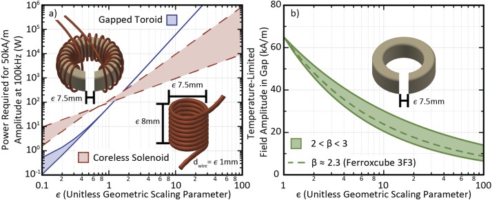
A plot of estimated power dissipation versus ε, shown in Fig. 6(a), compares two illustrative cases: a gapped 3F3 toroidal electromagnet and a finite solenoid with similar accessible working volume, both producing an AMF with an amplitude of 50 kA/m at a frequency of 100 kHz. The upper bound for the power required by the solenoid takes into account the proximity effect and skin effect expected with a solid copper conductor. The lower bound is based on linear scaling of estimated power dissipation using a measurement of litz wire resistance at 100 kHz. For the gapped toroid, power dissipation was estimated by the voltage drop across the shunt resistor Rshunt, and the relative contributions of the core and wire were estimated using the current and known resistance of the litz wire alone at 100 kHz. As expected, at the scale where the design was implemented, the gapped toroid is more efficient than the solenoid and its power dissipation is dominated by the core. Figure 6(a) suggests that the advantages of using a core to concentrate an AMF in a gap diminish rapidly with scale, though it should be noted that the specific crossover point depends on AMF frequency and field amplitude, core geometry, and material.
FIG. 6.
(a) Comparison of power requirements for a uniformly scaled gapped toroidal electromagnet and a solenoidal coil, generating the same AMF amplitude at a target point central to the working volume. The analysis is based on applying bounded scaling laws to extrapolate from measured power dissipation and resistances. (b) Estimate of allowable field amplitude in the gap for the constrained temperature change in the core. The estimate is based on applying a scaling law to a known set of aggressive operating conditions (65 kA/m at 100 kHz) for a Ferroxcube TX51/32/19-3F3 core with a 7.5 mm gap.
Maintaining the same field amplitude in electromagnets utilizing cores is actually far less scalable at high frequencies than an analysis of required power alone suggests. The preceding analysis assumed that the distribution and density of magnetic flux remains the same in scaled up cores, but large inductors are actually limited to lower flux densities due to heating.31 If the core is constrained to remain below a particular operating temperature, and the rate at which it can transfer heat to its surroundings is proportional to its surface area (a reasonable though slightly conservative approximation30), then the allowable energy loss density Pv,allowed is proportional to ε−1. Losses in core materials can be described as a function of the flux density, so Pv,allowed is also proportional to where Bmax is the peak flux density in the core and β is a parameter that is approximately 2.3 for 3F3 according to fits of the curves in Fig. 5(e).33 This implies that, at sizes sufficient to be limited by temperature increase, the maximum allowable field in the gap scales as ε−1/β. Consequently, larger designs would by necessity be limited to operation at a lower field amplitude, frequency, or duty cycle as illustrated in Fig. 6(b). Even for particularly well-designed flux paths such as the one presented in Gneveckow et al. or the special high surface area core design developed by Magforce, the use of a core still limits usable amplitudes.34,35 In principle, cooling copper tubing or litz wire in a coreless coil by flowing deionized water is comparatively feasible, even in cases with many kilowatts of dissipated power. Magnetic materials could still play a role in scaled up designs as shielding to reduce electromagnetic interference, but it is generally inadvisable for them to be incorporated into the main flux path of a large-scale AMF coil.
IV. MODERATE SCALE: 200 cm3 WORKING VOLUME
A. Resonant tank design
Section III showed that for working volumes larger than a few cubic centimeters, the most efficient designs surround the working volume with conductors carrying large currents. It is advisable to again employ a form of resonance, but this time a parallel LC configuration, or resonant “tank” [Fig. 7(a)], is more appropriate.36 Placing an inductor and capacitor in parallel amplifies the supplied current by the quality factor, Q, potentially producing large circulating currents at resonance without those currents needing to be carried by circuitry external to the tank.37 Q-factor is determined by the ratio of resistively dissipated power to peak stored energy per cycle,
| (13) |
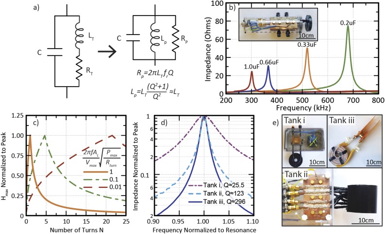
where RT is the resistance of the resonant tank, LT is its inductance, and is its resonant frequency. For an intuitive understanding of the frequency dependence of the load presented by a resonant tank with a large Q value, the circuit model in Fig. 7(a) offers a close approximation.37 Rp is the apparent real load of the tank at resonance, which depends on Q and LT,
| (14) |
In the limit of high Q values, the parallel inductance Lp is approximately equal to LT, as indicated in Fig. 7(a).38 Impedance measurements on a resonant tank with various capacitance values are shown in Fig. 7(b), illustrating how the impedance of a resonant tank is maximized at resonance and that Rp tends to increase with .
FIG. 7.
(a) Basic electrical schematic of a resonant tank for establishing large circulating currents and an intuitive model with nearly identical impedance vs frequency characteristics. (b) Impedance vs frequency for a handheld coil with various resonances. (c) Analysis of the role of voltage and power constraints on optimizing the number of turns in an idealized tank circuit. (d) Measured Q-factor values of resonant tanks with comparable inductance and resonance frequencies but different inductor design. (e) Photographs of the coils measured in (d). Tank i is a simple 8 turn copper tubing coil. Tank ii incorporates 4 parallel copper tube conductors into an 8 cm diameter two turn solenoid. Tank iii incorporates two parallel litz wires (42 × 10 × 10/44 AWG) surrounded by flexible Teflon tubing for flow.
To generate AMFs with amplitudes of up to 50 kA/m at frequencies of hundreds of kHz in volumes of tens of cm3, some laboratories employ induction furnaces or circuits based on them.3,18 These devices use an AMF generated by the current in a water-cooled copper tubing coil to inductively couple to conductive workpieces in order to deliver kilowatts of heat.39 Direct use of such furnaces as AMF sources may be effective in some cases, but they can be expensive in the 100 kHz-1 MHz frequency range and are typically limited to a fixed frequency. Furthermore, the fundamental purpose of an AMF coil is subtly different: most of the possible biomedical applications require the dissipation of a fraction of a milliwatt by the MNPs, implying that the tank operates essentially unloaded. Identifying the design goal as maximizing AMF amplitude at resonance for an unloaded resonant tank will subsequently be shown to suggest the use of fewer turns and parallel conductors, design characteristics that would be unwarranted for an inductive furnace application. (In its loaded state, the effective resistance introduced into the tank by a metal workpiece should already far exceed the resistance of the coil for efficient power transfer.)
General characteristics of the tank needed to maximize the field amplitude at resonance are suggested by a few basic circuit considerations that account for constraints on power and voltage. The field amplitude of a coil with N turns can be estimated by
| (15) |
Here, α is a proportionality factor determined by the coil geometry. The approximation is warranted for a tightly confined current distribution, such as in a low aspect ratio solenoid. For a long solenoid, the dependence on N is weaker because adding turns to the ends has diminishing marginal utility for increasing the field at the center. Assuming that each turn contributes a resistance Rturn to the coil such that its total resistance is given by RturnN, the maximum power that can be delivered to the coil Pmax limits the maximum value of the field,
| (16) |
In the idealized resonant tank of Fig. 7(a), the maximum circulating current is additionally limited by the inductive reactance of the coil XL in combination with the maximum voltage that can be applied to the tank Vmax. This maximum voltage limit is a design parameter set by the capacitor array of the tank or perhaps ultimately by safety and dielectric breakdown considerations, especially given the possible path to ground via the circulating cooling fluid. Consistent with the approximation made in Eq. (15), let XL ≈ 2πfrALN2, where AL is a geometry dependent inductance factor and is the resonant frequency,
| (17) |
| (18) |
Taken together, Eqs. (16) and (18) illustrate a fundamental tension in designing tank circuits that maximize the field amplitude. Increasing N to reduce the required power eventually increases the inductance enough that the field amplitude may instead become limited by the voltage that can be applied to the tank. Regardless of the particular geometry or exact dependence on N, a design maximizing the field amplitude in the working volume operates where these two limits coincide. Figure 7(c) illustrates this principle with generality for three cases defined in terms of the ratio of the prefactors in Eqs. (16) and (18). By attempting to reach higher field amplitudes in scaled up high frequency coils (increased AL), increasing Pmax, and decreasing Rturn, the optimal number of turns is pushed progressively lower and the maximum grows progressively sharper, indicating the advantage of geometries with a few turns that carry high currents. High Q-factor is desirable so that power can be delivered efficiently and the majority of resistive losses occur in the tank. This, however, must be achieved by decreasing tank resistance rather than by increasing tank inductance. Decreasing Rturn can be accomplished by the use of actively cooled litz wire or parallel conductors, though it should be noted that interconnect loss can become an important factor with highly paralleled conductors. Figure 7(d) shows how these strategies increase the Q-factor for several coils with comparable inductance and similar resonance frequency depicted in Fig. 7(e).
B. A case study: 8 cm diameter resonant tank for freely moving small animals
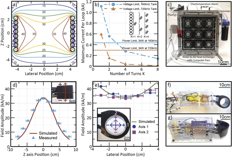
To demonstrate the application of these principles, a coil was constructed for experiments with awake, freely behaving mice. The first step was to establish the intended operating frequency and working volume. For this example, the target frequency was approximately 150 kHz and the working volume consisted of a cylindrical space with diameter 8 cm and height of at least 4 cm. This working volume lent itself to a finite solenoid fashioned from 0.25 in. copper tubing. Using the open-source finite element modeling software FEMM, an expected field profile could be simulated for magnetoquasistatic conditions,40 with the solenoid approximated by a stack of current-carrying rings. A design incorporating N = 8 conducting rings was selected due to the predicted uniformity of the field, which ranged from a minimum of 29 kA/m to a maximum of 44 kA over the entire working volume [Fig. 8(a)].
FIG. 8.
(a) Cross-sectional view of a finite element model plot for a stack of 8 rings carrying 434 A each. (b) Voltage and power limits used to determine the optimal number of parallel conductor groupings for the tanks appearing in (f) and (g). (c) Heat exchanger for cooling resonant tanks with rapidly flowed deionized water. (d) Field amplitude at 164 kHz as measured by 3 interpenetrating orthogonal inductive pickup loops along the z axis of the coil, as compared with the values predicted in (a). (e) Comparison of measured and simulated field amplitude values along lateral axes in the center of the coil. (f) Resonant tank for ∼160 kHz operation. Insulating black potting epoxy covers the turns of copper tubing. (g) Resonant tank for ∼720 kHz operation. Note two series layers of capacitors in the array to boost voltage tolerance.
The maximum field amplitude as limited by available power could be estimated by assuming a resistance per loop, Rloop, accounting approximately for the skin effect (2.0 mΩ). In order to avoid over-estimating the achievable AMF amplitude, it was prudent to suppose that perhaps 50% of the maximum DC supply power would be dissipated by the coil for an inverter circuit like the one discussed in Sec. IV C. In this case, the as- sumption implied an approximate Pmax of 3 kW. The maximum current per loop, Iloop, could then be estimated as follows:
| (19) |
Assuming that one or more metallized film capacitors (High Energy Corp. CHE6100M) were placed in parallel to handle the combined current of the loops, the maximum voltage that could be applied was limited to 600 V. In order to mitigate the inductance, some of the loops need to be grouped in parallel. Let K represent the effective number of turns of the coil accounting for parallel groupings. Here, K could assume the values 1 (8 parallel conductors), 2 (4 parallel conductors), 4 (2 parallel conductors), or 8 (1 single conductor). The same finite element model could then be used to determine how many turns should be placed in parallel by integrating over the volume to find the magnetic field energy, U. This quantity is relatable to inductance L by K and the current per loop Iloop,
| (20) |
Figure 8(b) shows how changing the effective number of turns K changes the influence of the 600 V limit on the maximum current per loop. Since Fig. 7(c) suggests an optimal design in the vicinity of the crossover between the voltage and power limit, the two-turn solenoid with four parallel conductors was the best available choice. The overall current in the tank with this selection was predicted to be approximately 1.7 kA, and although this tremendous current was distributed across the four conductors and three parallel capacitors, effective cooling was necessary to avoid failure due to Joule heating. This was accomplished with a custom heat exchanger that rapidly circulated deionized water from a reservoir [Fig. 8(c)].
The AMF amplitude developed by this apparatus as measured by a homemade three-axis inductive field probe consisting of three orthogonal loops of litz wire with known diameter (13 mm) closely matched the profile predicted by the magnetoquasistatic finite element model [Figs. 9(d) and 9(e)]. The field strength along the lateral axes of the tank is somewhat less symmetric in the actual coil [Fig. 8(f)], as expected from the simplifying approximation of cylindrical symmetry in the simulation. Under these operating conditions, 4.2 kW were delivered, implying that some 70% of this power was dissipated in the coil itself, with the remainder presumably accounted for by the resonant capacitors and switching losses in the inverter. Comparable operation at higher frequencies in a coil with identical geometry requires raising the voltage tolerance of the tank. For example, a coil intended to generate a lower AMF amplitude at a frequency of ∼680 kHz uses a series capacitor array to double the maximum voltage [Fig. 8(g)].
FIG. 9.
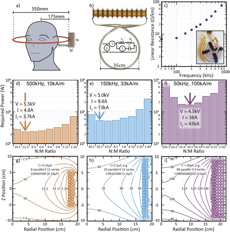
(a) Geometric starting point for a scaled up design for applying AMFs to a human head. (b) Sketch of top view of a scaled up resonant tank, along with definitions of quantities appearing elsewhere in the figure. (c) Measured linear resistance versus frequency for 42 × 10 × 10/44 AWG litz wire surrounded by Teflon tubing for flow. [(d)–(f)] Power dissipation required to achieve stated target field amplitude and frequency in the center a coil with a fixed number of parallel litz wire conductors arranged in various rectangular bundles. [(g)–(i)] Cylindrical magnetostatic finite element models of magnetic field magnitude for the recommended configurations. Possible capacitor array designs are indicated to corroborate feasibility.
C. Full bridge driver
Commercial amplifiers with built-in protections against damage from mismatched loads are undoubtedly the most convenient means to supply tens to a few hundred watts of power to AMF setups with adjustable resonance frequencies. However, the tank circuits described in Sec. IV B require substantially more power to reach comparable amplitudes. Linear amplifiers capable of supplying kilowatts do exist but can be prohibitively expensive. Driving AMF coils at resonance implies that while frequency adjustability is a desirable feature, linear amplification over a wide bandwidth is not actively utilized and is therefore a waste of both expense and efficiency. Instead, a custom full bridge inverter was developed to convert a regulated DC supply (e.g., 600 V, 10 A maximum) to a square wave with a frequency set by an input signal from a function generator. More sophisticated inverter designs are available,41 but a full bridge was selected on the basis of its simplicity and it proved sufficient for the purpose. Additional discussion of the inverter as well as the role of a transformer with leakage inductance that impedes high frequency components of the square wave can be found in the supplementary material.
V. OUTLOOK FOR CLINICAL SCALABILITY: 1000 cm3 WORKING VOLUME
Research on biomedical applications of MNPs acted upon by AMFs implicitly assumes that particular AMF conditions employed experimentally can be feasibly scaled to the human body. Studies are conducted over a wide range of AMF conditions, often with a markedly higher H0 f products than the AMF that can be produced by a clinical scale electromagnet.34 The reasoning behind the resonant tanks demonstrated in Sec. IV may be extended to coils suitable for reaching a target deep inside a human brain.
Recalling the conclusion of the earlier thought experiment of coil scalability (Fig. 6), a useful geometric starting point for designing a suitable tank is a (purely hypothetical) superconducting circular loop with a diameter of 35 cm [Fig. 9(a)] that can accommodate a head with ample room left for insulation. Consistent with the analysis in Fig. 7(c), the large voltages already necessitated by the inductance of this single loop recommend against a design with multiple turns [Fig. 9(b)]. Taking the target point to be the center of the loop, a bound on the minimum current needed to produce an amplitude meeting the H0 f product limit can be calculated, since distributing current density by adding additional parallel conductors will only increase the total required current. In envisioning how to replace this loop with real wire, e.g., water-cooled litz wire, it is neither practical to restrict the required current to a single conductor nor to attempt to distribute it over thousands of parallel conductors. The latter strategy would, in principle, minimize the necessary power, but it does so at the expense of dramatically increasing the total required current, which causes the capacitor array to grow formidably in size and expense. A rational compromise is to set a target value for power to be dissipated per wire. The heat exchanger in Fig. 8(c) was able to compensate for about 1 kW of power dissipated per conductor, so this quantity can serve as a conservative limit for the purpose of discussion. Using measurements of the linear resistance of the litz wire incorporated into the coil in Fig. 9(c) and the physical dimensions of the loop, the maximum current per wire can be estimated, which suggests the necessary number of conductors.
To determine an efficient geometric distribution of these parallel conductors, one can assume that together they form an N by M rectangular cluster of wires with spacing that accounts for the outer diameter of the surrounding cooling tube [Fig. 9(a)]. Then the total resistance of the coil and the total field produced at its center may be found by a sum or superposition of constituent rings, respectively. Figures 9(d)–9(f) illustrate how total dissipated power varies with M and N for a fixed total number of conductors. At low frequencies (e.g., 50 kHz) where large currents are required, the necessary power is >150 kW [Fig. 9(f)], a level that far exceeds that of the higher frequency alternatives. In cases where total required power is comparable for two possibilities, higher N improves field uniformity [Figs. 9(e) and 9(h)]. A finite element magnetoquasistatic model for this distribution of current predicts the variation of the field as shown in Figs. 9(g)–9(i) and additionally offers a means to calculate inductance using the magnetic field energy. The capacitor array must withstand both the total resonance current and the voltage applied to produce it. Such an array would consist of up to several hundred parallel and series elements that require cooling and account for a significant portion of the cost of such a system (Fig. 9).
This analysis has several limitations. Notably, the current was assumed to be uniformly distributed over the parallel conductors. A more detailed design might balance the inductance and resistance of the conductors simply by constraining them to the same length and distributing their connections to the capacitor array in a way that mitigated differences in contributions to inductance. Also, the power dissipation of the capacitor array was neglected, so required power would certainly exceed the values in Figs. 9(d)–9(f), though the array would operate at a lower current density than the coil. Crossover of the wires as they connect to the capacitor array [Fig. 9(b)] would add some resistance, but the field would drop off more quickly far from the resonant tank, a feature that could help reduce its inductance.
VI. CONCLUSION
In identifying useful methods for producing AMFs, the most important consideration was scale. This paper began with simple, inexpensive designs that used soft ferromagnetic cores to expose ∼2 cm3 working volumes to amplitudes of 10s of kA/m at frequencies between 100 kHz and 1 MHz. With little required power, these electromagnets can offer valuable experimental data on trends in MNP heating or test the feasibility of ideas for biomedical applications in vitro. The advantage of this approach diminishes rapidly as coils become larger and the need for AMF generation in volumes suitable for freely behaving animals necessitates strikingly different coil designs employing resonant tank circuits with more than 1 kA of circulating current.
By extending the same principles to hypothetical setups with dimensions required for clinical applications, the analysis reflected increasing challenges, cost, and complexity for scaling up AMF coils. Previous work has suggested that the constraint of an H0 f product limit alone is insufficient to assert an unambiguously optimal type of MNPs; differing magnetic properties can lead to markedly different AMF conditions for optimal heating.17 The relative technical feasibility and physiological suitability of these optimal AMF conditions can vary markedly. This suggests that the scalability of AMF setups is a consideration that must help to inform materials design of MNPs if the techniques employing them are to be realized in the clinic.
SUPPLEMENTARY MATERIAL
See supplementary material for a discussion of additional modifications that can be made to a gapped toroid for a more uniform flux distribution and designs for the inverter that drives the resonant tank circuits. Detailed plans including part lists, board layouts, technical drawings, and other documentation sufficient to reproduce these setups will be provided upon request to either of the corresponding authors.
ACKNOWLEDGMENTS
This work was supported in part by the Defense Advanced Research Projects Agency (DARPA) under the ElectRx Program (No. HR001-15-C-0155) and by the National Institutes of Health BRAIN Initiative (No. IR01MH111872-01). M.G.C. was supported by the Department of Defense through the National Defense Science and Engineering Graduate (NDSEG) Fellowship. The work of C.H. was supported by the National Science Foundation under CAREER Award to P.A. (No. CBET-1253890) and Center for Materials Science and Engineering Research Experience for Undergraduates program, as part of the MRSEC program under Grant No. (DMR-1419807).
REFERENCES
- 1.Pankhurst Q. A., Connolly J., Jones S. K., and Dobson J., J. Phys. D: Appl. Phys. 36(13), R167 (2003). 10.1088/0022-3727/36/13/201 [DOI] [Google Scholar]
- 2.Pankhurst Q. A., Thanh N. T. K., Jones S. K., and Dobson J., J. Phys. D: Appl. Phys. 42(22), 224001 (2009). 10.1088/0022-3727/42/22/224001 [DOI] [Google Scholar]
- 3.Thomas C. R., Ferris D. P., Lee J.-H., Choi E., Cho M. H., Kim E. S., Stoddart J. F., Shin J.-S., Cheon J., and Zink J. I., J. Am. Chem. Soc. 132(31), 10623–10625 (2010). 10.1021/ja1022267 [DOI] [PubMed] [Google Scholar]
- 4.Schuerle S., Dudani J. S., Christiansen M. G., Anikeeva P., and Bhatia S. N., Nano Lett. 16(10), 6303–6310 (2016). 10.1021/acs.nanolett.6b02670 [DOI] [PMC free article] [PubMed] [Google Scholar]
- 5.Loynachan C. N., Romero G., Christiansen M. G., Chen R., Ellison R., O’Malley T. T., Froriep U. P., Walsh D. M., and Anikeeva P., Adv. Healthcare Mater. 4(14), 2100–2109 (2015). 10.1002/adhm.201500487 [DOI] [PubMed] [Google Scholar]
- 6.Monsalve A., Bohrquez A. C., Rinaldi C., and Dobson J., IEEE Magn. Lett. 6, 1–4 (2015). 10.1109/lmag.2015.2477271 [DOI] [Google Scholar]
- 7.Huang H., Delikanli S., Zeng H., Ferkey D. M., and Pralle A., Nat. Nanotechnol. 5(8), 602–606 (2010). 10.1038/nnano.2010.125 [DOI] [PubMed] [Google Scholar]
- 8.Stanley S. A., Gagner J. E., Damanpour S., Yoshida M., Dordick J. S., and Friedman J. M., Science 336(6081), 604–608 (2012). 10.1126/science.1216753 [DOI] [PMC free article] [PubMed] [Google Scholar]
- 9.Chen R., Romero G., Christiansen M. G., Mohr A., and Anikeeva P., Science 347(6229), 1477–1480 (2015). 10.1126/science.1261821 [DOI] [PubMed] [Google Scholar]
- 10.Meister M., eLife 5, e17210 (2016). 10.7554/eLife.17210 [DOI] [PMC free article] [PubMed] [Google Scholar]
- 11.Chiu-Lam A. and Rinaldi C., Adv. Funct. Mater. 26(22), 3933–3941(2016). 10.1002/adfm.201505256 [DOI] [PMC free article] [PubMed] [Google Scholar]
- 12.Rudolf H., Silvio D., and Matthias Z., Nanotechnology 21(1), 015706 (2010). 10.1088/0957-4484/21/1/015706 [DOI] [PubMed] [Google Scholar]
- 13.Carrey J., Mehdaoui B., and Respaud M., J. Appl. Phys. 109(8), 083921 (2011). 10.1063/1.3551582 [DOI] [Google Scholar]
- 14.Ruta S., Chantrell R., and Hovorka O., Sci. Rep. 5, 9090 (2015). 10.1038/srep09090 [DOI] [PMC free article] [PubMed] [Google Scholar]
- 15.Usov N. A. and Barandiarán J. M., J. Appl. Phys. 112(5), 053915 (2012). 10.1063/1.4749799 [DOI] [Google Scholar]
- 16.Mehdaoui B., Meffre A., Carrey J., Lachaize S., Lacroix L.-M., Gougeon M., Chaudret B., and Respaud M., Adv. Funct. Mater. 21(23), 4573–4581 (2011). 10.1002/adfm.201101243 [DOI] [Google Scholar]
- 17.Christiansen M. G., Senko A. W., Chen R., Romero G., and Anikeeva P., Appl. Phys. Lett. 104(21), 213103 (2014). 10.1063/1.4879842 [DOI] [Google Scholar]
- 18.Stanley S. A., Sauer J., Kane R. S., Dordick J. S., and Friedman J. M., Nat. Med. 21(1), 92–98 (2015). 10.1038/nm.3730 [DOI] [PMC free article] [PubMed] [Google Scholar]
- 19.Lacroix L.-M., Carrey J., and Respaud M., Rev. Sci. Instrum. 79(9), 093909 (2008). 10.1063/1.2972172 [DOI] [PubMed] [Google Scholar]
- 20.Connord V., Clerc P., Hallali N., El Hajj Diab D., Fourmy D., Gigoux V., and Carrey J., Small 11(20), 2437–2445 (2015). 10.1002/smll.201402669 [DOI] [PubMed] [Google Scholar]
- 21.Hergt R. and Dutz S., J. Magn. Magn. Mater. 311(1), 187–192 (2007). 10.1016/j.jmmm.2006.10.1156 [DOI] [Google Scholar]
- 22.Bottomley P. A. and Andrew E. R., Phys. Med. Biol. 23(4), 630 (1978). 10.1088/0031-9155/23/4/006 [DOI] [PubMed] [Google Scholar]
- 23.Feynman R. P., Leighton R. B., and Sands M. L., The Feynman Lectures on Physics, Definitive ed. (Pearson/Addison-Wesley, San Francisco, 2006). [Google Scholar]
- 24.Autler S. H., Rev. Sci. Instrum. 31(4), 369–373 (1960). 10.1063/1.1716985 [DOI] [Google Scholar]
- 25.Hanson A. J., Belk J. A., Lim S., Perreault D. J., and Sullivan C. R., presented at the 2015 IEEE Energy Conversion Congress and Exposition, 2015. [Google Scholar]
- 26.Connord V., Mehdaoui B., Tan R. P., Carrey J., and Respaud M., Rev. Sci. Instrum. 85(9), 093904 (2014). 10.1063/1.4895656 [DOI] [PubMed] [Google Scholar]
- 27.Erickson R. W. and Maksimovic D., presented at the PESC 98 Record 29th Annual IEEE Power Electronics Specialists Conference, 1998. [Google Scholar]
- 28.Kassakian J. G., Schlecht M. F., and Verghese G. C., Principles of Power Electronics (Addison-Wesley, Reading, Massachusetts, 1991). [Google Scholar]
- 29.Rand A., IEEE Trans. Compon. Parts 10(1), 31–35 (1963). 10.1109/tcp.1963.1134806 [DOI] [Google Scholar]
- 30.Perreault D. J., Hu J., Rivas J. M., Han Y., Leitermann O., Pilawa-Podgurski R. C. N., Sagneri A., and Sullivan C. R., presented at the IEEE Applied Power Electronics Conference and Exposition, 2009. [Google Scholar]
- 31.Sullivan C. R., Reese B. A., Stein A. L. F., and Kyaw P. A., presented at the International Symposium on 3D Power Electronics Integration and Manufacturing, 2016. [Google Scholar]
- 32.Sullivan C. R., IEEE Trans. Power Electron. 14(2), 283–291 (1999). 10.1109/63.750181 [DOI] [Google Scholar]
- 33.Steinmetz C. P., Trans. Am. Inst. Electr. Eng. IX(1), 1–64 (1892). 10.1109/t-aiee.1892.5570437 [DOI] [Google Scholar]
- 34.Gneveckow U., Jordan A., Scholz R., Brüß V., Waldöfner N., Ricke J., Feussner A., Hildebrandt B., Rau B., and Wust P., Med. Phys. 31(6), 1444–1451 (2004). 10.1118/1.1748629 [DOI] [PubMed] [Google Scholar]
- 35.Feucht P., U.S. patent 6,575,893 (10 June 2003).
- 36.Garaio E., Collantes J. M., Plazaola F., Garcia J. A., and Castellanos-Rubio I., Meas. Sci. Technol. 25(11), 115702 (2014). 10.1088/0957-0233/25/11/115702 [DOI] [Google Scholar]
- 37.American Radio Relay League, The ARRL Handbook for Radio Communications (ARRL, Newington, CT, 2013), Chap. 19. [Google Scholar]
- 38.Lee T. H., Planar Microwave Engineering: A Practical Guide to Theory, Measurement, and Circuits (Cambridge University Press, Cambridge, England, New York, 2004). [Google Scholar]
- 39.Khan I., Tapson J., and de Vries I., presented at the IEEE International Symposium on Industrial Electronics, 1998. [Google Scholar]
- 40.Haus H. A. and Melcher J. R., Electromagnetic Fields and Energy (Prentice Hall, Englewood Cliffs, NJ, 1989). [Google Scholar]
- 41.Rodriguez J. I. and Leeb S. B., IEEE Trans. Power Electron. 21(6), 1607–1617 (2006). 10.1109/tpel.2006.882965 [DOI] [Google Scholar]
Associated Data
This section collects any data citations, data availability statements, or supplementary materials included in this article.
Supplementary Materials
See supplementary material for a discussion of additional modifications that can be made to a gapped toroid for a more uniform flux distribution and designs for the inverter that drives the resonant tank circuits. Detailed plans including part lists, board layouts, technical drawings, and other documentation sufficient to reproduce these setups will be provided upon request to either of the corresponding authors.


