

Abstract
In this article, we present a novel class of robots that are able to move by growing and building their own structure. In particular, taking inspiration by the growing abilities of plant roots, we designed and developed a plant root-like robot that creates its body through an additive manufacturing process. Each robotic root includes a tubular body, a growing head, and a sensorized tip that commands the robot behaviors. The growing head is a customized three-dimensional (3D) printer-like system that builds the tubular body of the root in the format of circular layers by fusing and depositing a thermoplastic material (i.e., polylactic acid [PLA] filament) at the tip level, thus obtaining movement by growing. A differential deposition of the material can create an asymmetry that results in curvature of the built structure, providing the possibility of root bending to follow or escape from a stimulus or to reach a desired point in space. Taking advantage of these characteristics, the robotic roots are able to move inside a medium by growing their body. In this article, we describe the design of the growing robot together with the modeling of the deposition process and the description of the implemented growing movement strategy. Experiments were performed in air and in an artificial medium to verify the functionalities and to evaluate the robot performance. The results showed that the robotic root, with a diameter of 50 mm, grows with a speed of up to 4 mm/min, overcoming medium pressure of up to 37 kPa (i.e., it is able to lift up to 6 kg) and bending with a minimum radius of 100 mm.
Keywords: : growing robots, 3D printing, additive manufacturing, plant-inspired robots, soft robots
Introduction
The emergence of bioinspired approaches represents an innovative way to rethink robot design since new strategies, new patterns of movement, and new sensing and actuation abilities can be proposed to build innovative robotic systems.1 This bioinspired evolution of robotics also supports the effectiveness of soft bodies, as living organisms exploit soft tissues and compliant structures to move effectively in complex natural environments.1,2
Soft robotics, which focuses on generating devices based on compliant and deformable materials in the interaction with the environment,3 represents a recent disruptive technology and an approach to develop new classes of robots expected to act in natural, unstructured environments (e.g., locomotion in uncertain terrains, manipulation of unknown objects, and accomplishment of non-predetermined tasks) and to interact more safely with humans.4,5 Structures made of soft matter with variable stiffness properties6,7 give rise to continuum soft robots that, differently from the former rigid-link robots, are able to undergo elastic deformation at any point in their structures for producing structural movements.8–10
The use of soft materials and continuum deformations paves the way for scientific and technological challenges, which include developing control solutions that are more difficult in computational terms, defining new design rules, and also developing and adopting innovative manufacturing technologies, including combinations of advanced fabrication techniques (e.g., micromolding,11 soft lithography,12 and multimaterial-embedded three-dimensional (3D) printing13). The complexity of developing bioinspired soft robots is increased by the need for mimicking biological system capabilities in being energetically efficient, in changing their morphology, in adapting their body and functionality in their lifetime, by growing, or even by a morphological environmental adaptation.14,15
Hence, the challenge ahead for soft robotics is to further develop the abilities for robots to grow, evolve, self-heal, develop, and biodegrade, which are the ways that robots can adapt their morphology to the environment.16 In this context, growth is a very interesting possibility that would allow the creation of robots endowed with new and unpredictable abilities of movement, able to assume any shape on the basis of the task to be accomplished. An example of these approaches is given by the spider-like robot proposed in a study by Wang et al.,17 where improved locomotion capabilities in a 3D space are obtained by thermoplastic spinning of draglines. Innovative solutions to address these challenges can be obtained by studying and imitating plants. Unlike the majority of animals, which grow until they reach maturity, plants grow for their entire life.
In this work, we present a new concept of a self-growing robot that is inspired by the movement and adaptation capabilities of plant roots in soil. By uncovering the fundamental aspects of the chosen biological model, we aim to develop novel robotic morphologies and controllers specifically optimized for burrowing.
Soil is a poorly explored environment in robotics. Some of the robotic solutions developed in this direction are inspired by legless animals because of their exceptional ability to move in unstructured environments in different conditions (rocks, desert, forests, underground, etc.) and their high stability (barycenter in proximity to the soil).18 There are already robots inspired by legless animals for manipulation and movement in 3D spaces,19 medical applications,20,21 pipe inspection,22 and soil locomotion.23,24 Although these robots have implemented interesting solutions, the penetration of deep soil remains challenging due to the peripheral frictional interaction with the soil and the power transmission.
Recently, plant roots have been proposed as a new biological model for developing advanced soil drilling robotic solutions. Plant roots are excellent natural diggers, and their characteristics such as adaptive growth, low-energy consumption movements, and the capability of penetrating the soil at any angle are interesting from an engineering perspective.25 A first attempt at developing a mechanism inspired by plant roots was reported in an article.26 In this work, we translated the outward flow of growing cells at the tip of the root and the low frictional interaction with the soil provided by sloughing cells to an engineering prototype that is able to penetrate into the soil.
The system simulates these features by the outward movement of a soft sleeve from the internal hole of a rigid tube to its external face. In addition, we studied and imitated the positive effect of root hairs in providing anchorage and preventing upward movement instead of downward penetration by adding lateral hairs to the sleeve. The main challenge of the proposed solution is the tissue flexibility that does not prevent the transmission of soil pressure to the rigid shaft during the penetration. This problem becomes more significant when the system penetrates into deeper soil, because the medium lateral pressure to this system becomes higher. Moreover, a long and rigid shaft that does not bend or change its orientation offers a limited number of robotic applications.
To overcome these limits, as given in Ref.,27 we proposed another artificial solution that was based on the root-growing strategy. Plants are able to efficiently penetrate different types of soil because they grow at the apical level of their roots by the division and generation of new cells and elongate on absorbing water from their external environment by osmosis. These phenomena occur in the root meristem zone and elongation region, respectively.28 Analogously to a natural organism, the root-like device penetrates the medium by imitating the new cell generation by adding layers of artificial material at its tip level, which results in a growth process. This addition process provides a pushing action for overcoming the soil pressure and penetrating the soil, while at the same time it also elongates the structure of the artificial root.
The mechanism that performs the material deposition process (called the growing mechanism) has a short length and slides inside its self-developed tubular structure and always remains at the apical part of the robotic root. The body of the robot does not move with respect to the soil and only its apical part performs the penetration. This localization of the frictional interactions at the tip level makes the behavior and efficiency of the system independent from its length, in contrast with the sloughing mechanism.26
Even if this system successfully validates and demonstrates the advantages of following the plant root strategy in penetration, the proposed solution will still not be able to provide the capability of deep penetration because the new layers of material added at the tip level are not sufficiently sticky to build a proper structure, which makes the system limited to deep penetration and bending. In fact, in addition to straight penetration, the plant roots can perform a bending task in soil for following/escaping from an environmental stimulus or avoiding an obstacle (tropisms29–32) by the differential elongation of the cells in the elongation region. Mimicking this feature, we can improve the capabilities of the robotic root to explore and penetrate unknown environments.
In the current work, we propose a new generation of growing robots able to build their own bodies. In particular, we present a novel robotic system, inspired by plant roots, able to move in a granular medium through a layer-by-layer deposition process. These features are achieved by the integration of a customized 3D printer inside the root. To the best of our knowledge, this is the first robot able to grow by changing shape and expanding its body on the basis of the selected task and that integrates a 3D printer-based solution. Taking advantage of these characteristics, the robotic roots are able to move inside a medium by growing their body in a straight direction or by bending. These growing roots have been integrated in a PLANTOID,33 which is a plant root-inspired robot that embeds innovative technologies, such as plant-inspired materials in its leaves34 and plant-inspired roots with soft bending capabilities.33
This article is organized as follows. First, we present the robot design, modeling of locomotion, details of the deposition strategy and results of the experimental trials. Next, we describe the robot prototype fabrication and the related control architecture and then provide details on the setups and experiments used for the robot characterization. Last, we discuss the limits and advantages of the current version of the robot, as well as possible future applications.
Results
Growing robot design
The robotic root is designed by exploiting the 3D printer and classic FDM (fused deposition modeling) approaches. Each robotic root includes a tubular body, a growing head, and a sensorized tip that commands the robot behaviors (Fig. 1). The growing head is a customized 3D printer-like system that builds the tubular body of the root in the format of circular layers by fusing and depositing the filament of a raw material at the tip level. This miniature 3D printer-like machine includes an extruder and plotting units (Fig. 2A, B). The extruder unit (similar to FDM 3D printers) includes a gear-based feeder mechanism, a guiding tube, a heater as a liquefier, and a nozzle (Fig. 2B). The gear-based feeder provides a gripping action to the thermoplastic filament, pulling it from the reservoir and then pushing it toward the heater and nozzle.
FIG. 1.

A general view of a PLANTOID: a robot with several (two in the picture for clarity) growing roots for soil exploration. Each root has its local control unit at the tip level, while another electronic unit placed inside the trunk manages the communications between the roots and an operator. The root tips are equipped with soft touch sensors at their apex to measure the soil pressure and detect obstacles, a gravity sensor to determine the tip orientation, and sensors for temperature, humidity, and chemicals on their peripheral surface to monitor the surrounding environmental conditions and implement the plant root behaviors.33
FIG. 2.

CAD model of the growing mechanism, including the sensorized tip, (A) the plotter unit, (B) the extruder unit, and (C) the sensorized tip decoupled from the growing mechanism by means of a ball bearing, while their relative rotation can be monitored by a magnetic encoder mounted on the control unit and a magnet at the axis of the tip.
The guiding tube changes the direction of the filament (∼90°) from the external gate of the feeder to the internal gate of the heater. The components of the extruder are mounted on two parallel disks, called the deposition disk and rim (Fig. 2). After the final assembly, these disks are fixed together and the deposition process occurs by the relative rotational motion of these disks with respect to the tubular body of the root. The plotting unit is responsible for providing this relative rotational motion by means of a DC gear motor and an internal gear, placed between the motor holder disk and the deposition head (Fig. 2A). This assembly smoothly functions as a flat bearing due to two couples of raceways on the corresponding surfaces of the disks filled with bearing spheres.
The internal gear, which also functions as the main body of the 3D printer, is interfaced with the root tubular body through four flexible clamping fingers installed on its circumferential sides (Fig. 2A). The flexibility of these fingers and the sharpness of their corners provide an interaction with the tubular body that prevents the rotation of the growing mechanism inside the printed tubular body and, at the same time, allows the axial sliding of the growing system along the growth direction. The deposition process of the root body occurs under the rim of the deposition head. The addition of each new layer between the deposition head and the tubular body pushes the growing tip forward to penetrate the soil. The pressure generated by the soil on the deposited layers guarantees the realization of a compact and solid robotic root structure because they stick to each other.
A customized tip, including miniaturized sensors (see Sadeghi et al.33 for details) and connected through a bearing to the deposition head, collects environmental information and decides on the growth orientation on the basis of the embedded behavior (Fig. 2C).33
Robotic root movement in soil by growing
The simultaneous actions of feeding and rotational plotting permit the layer-by-layer deposition of the fused material in a tubular shape for the realization of the root body. The layers can be deposited in complete circles or in sectors of circular patterns. The compliancy and softness of the fused material can be tuned by controlling the heater temperature and the feeding speed; this aspect, together with the independency of the extruder and the plotting units, allows controlling the speed and orientation of the plotting. These features provide flexibility in the resulting thickness, shape, and position of the layers. Similar to our previous work,27 the force transmitted from the anchored robotic root body to the advancing tip can be modeled as the force applied by a screw by exploiting the helical deposition of the filament material.
Nevertheless, different from the previous work in which the filament diameter (d) was assumed constant during the deposition process, in this case, due to the heating and the fusion process, after deposition, the filament section changes to an almost rectangular shape (with a thickness t and a width s) (Fig. 3). A rectangular deposited layer of length Ld can be obtained by a filament of raw material with an initial diameter d and length Lr.
 |
FIG. 3.

(A) Schematic view of the growing mechanism. Red arrows represent forces acting on the system during the deposition process: F is the force applied by the plotter motor, W is the vertical resistance during penetration (composed by external resistance WS and internal frictional forces Wf), M is the torque required for both deposition and penetration processes to overcome W, t is the thickness of the filament after the deposition, and D is the external diameter of the tubular body. (B) Equilibrium of forces acting on the deposited layer for one complete unwound turn, where α is the angle made by the helix of the deposited filament with respect to a plane perpendicular to the axis of the tubular body, N is the reaction force, and μ is the friction coefficient between deposited layer and deposition head.
Considering the helical shape of the deposited layers, the tip penetrates a distance equal to the layer thickness in each complete deposition cycle. Therefore, the penetration depth P, resulting from the deposition of a layer with length Ld, thickness t, and width s in a tubular root shape with an external diameter D, is given as follows:
 |
where α is the helix pitch angle, which can be expressed as follows:
 |
A successful plotting elongation process can be performed when the system has enough power to overcome the internal force Wf (generated by the clamping fingers) and the external axial forces Ws (e.g., vertical force generated by soil pressure). Defining μ as the contribution of the friction force between the depositing layer and deposition head, the required torque M at the deposition head is
 |
Playing with the deposition parameters (i.e., heater temperature, feeding speed, and deposition speed), it is possible to change the thickness of the material and obtain different α values. Thus, the generated axial force and the penetration speed can be tuned on the basis of the medium that the robot has to penetrate. The provided flexibility in the deposition process also permits the addition of different amounts of material on the sides of the robotic root structure and creates an asymmetry with a consequent bending in the lower deposition direction (Fig. 4B, C). This asymmetry caused by the material's differential deposition imitates a similar behavior observed in natural roots that is generated by the differential division and elongation of new cells at their apexes, causing the bending of the root.
FIG. 4.

Possible penetration strategies that the robot can adopt to move straight or bend; (A) a symmetric deposition of material behind the deposition head results in straight growth; (B) a bending of the robotic root caused by deposition of different thickness material layers; (C) a bending of the robotic root caused by the addition of a variable number of layers on a side of the root body (combination of complete cycles and sectors of cycles); (D) definition of the curvature parameters in the cases of different numbers of deposited layers; and (E) the curvature radius of the structure as a function of the ratio between heights of layers (case A) or a number of layers (case B) deposited on the two sides, calculated, respectively, by means of equation (7A) or (7B).
From an exquisite engineering view, the bending can be compared to the locomotion of a classic two-wheel mobile robot on a planar surface, where the deposition speed on the two sides of the structure is equivalent to the speed of the two wheels. In particular (Fig. 4D), the instantaneous curvature of the structure rc can be obtained as follows:
(A) a differential deposition of the same number of layers k with different thicknesses h1 and h2 (Fig. 4B) or
(B) a differential deposition of different numbers of layers n and m with the same thickness h (Fig. 4C).
Using rin for the internal structure curvature radius, rex for the external one, and β for the curvature angle, we obtain for the two cases
Ideally, case A creates a more continuous structure because by tuning the diameter of the extruded filament it is possible to deposit a more homogeneous helical structure. This structure can be realized by maintaining a constant feeding speed and extrusion temperature and regulating the plotting speed. However, tuning precisely the plotting speed is a challenging task and turning in the same direction can also create the problem of cable twisting. In our implementation, we used case B because it can intrinsically prevent the problem of twisting of the filament of the raw material and power wires (see more details in the Deposition Process section); moreover, the deposition process needs less accuracy because the softness of the extruded filament compensates intrinsically the gaps created by the on/off deposition strategy.
In the performed experiments, straight growth was obtained by a symmetric deposition of layers (n/m = 1) and bending is obtained by depositing different numbers of layers (n/m > 1). A value of 2 for the n/m deposition ratio was sufficient to obtain the minimum bending radius RM of 100 mm in the root structure.
Deposition process
The filament extending from the nozzle should be partially liquefied. The main challenge is to obtain a material that is externally sticky enough to permit the layers to attach together but internally semisolid such that it is sufficiently strong enough to overcome the soil pressure and push the tip ahead. Indeed, if the material that comes out from the nozzle is completely liquefied, it is squeezed around by the soil pressure and no penetration can happen. On the contrary, if it is too solid, penetration can occur but no structure would be obtained.
The optimal temperature and feeding speed values were experimentally defined as 180–200°C and 8 mm/s, respectively, to obtain successful penetration and fabrication of the growing structure. We selected strategy B for the bending, so the deposition process was planned with alternating changes in the orientation of the plotting cycles. This strategy prevents the accumulation of twisting and torsion in the polylactic acid (PLA) thermoplastic filament pulled from the reservoir and in the power wires connected to the trunk. The deposition strategy can be arbitrary; in the following, we consider that the deposition occurs by a sequence of straight growing (SG) cycles followed by a single differential sector deposition (DD), and we call the ratio between these two parameters the deposition ratio (K = SG:DD), where DD is always equal to 1. The maximum curvature is obtained for K = 1:1, which corresponds to a single complete layer deposition followed by a single sector deposition so that n/m = 2.
With the proposed strategy (B), after finishing some cycles of deposition in a certain direction (Fig. 5A), it is necessary to stop the feeding of the raw material before stopping the plotting motion (Fig. 5B). This provides an empty gap in front of the nozzle (Fig. 5C) that allows the easy exit of the material for plotting in an inverse direction (Fig. 5D–F) (Supplementary Video S1; Supplementary Data are available online at www.liebertpub.com/soro). The same strategy is used for the differential deposition during bending that requires the continuous inversion of the plotting orientation to obtain complete and incomplete layers. The relevant parameters to accomplish the growing task are the central deposition angle (θ); bending direction (θ + 180°); amplitude of the angle at which the filament is applied differentially, named the differential deposition sector (ΔD); the angle before the inversion process between the stop of the feeding and the stop of the plotting, named the extra angle (EA); and the deposition ratio (K) (Fig. 5).
FIG. 5.

Schematic view of the parameters selected for the material deposition process (left); representation of the phase sequence required for straight growth and bending (right). (A) The filament is first deposited toward the right; (B) the feeding is stopped while the rotation of the deposition head continues for an EA of amplitude EA to remove the material in front of the nozzle; (C) the rotation is stopped for 3–5 s more to cool down the old layer; (D–F) the process restarts in the opposite direction for depositing the next K layers. EA, extra angle.
The differential deposition task includes three states:
(1) The first state starts when the deposition and feeding motor are turned on. The filament comes out from the extruder and is deposited on the old material, realizing the structure and at the same time pushing the tip ahead (Fig. 5A);
(2) When the extruder goes out from the differential deposition sector, the feeding motor is stopped, while the plotting rotation continues for an EA of amplitude EA before the plotting motor is stopped (Fig. 5B); and
(3) After a few seconds (3–5 s), necessary for cooling the old layer (Fig. 5C), the plotting rotation starts in the opposite direction together with feeding (Fig. 5D, E). The filament rises above the old layer (Fig. 5E) and continues to grow (feeding+deposition) for a defined number (K) of complete layers (Fig. 5F) until the next inversion.
Validation of the robot movement by growing ability
The prototype was tested in three different scenarios (see the Materials and Methods section for details). The performed experiments were particularly aimed at establishing (1) the thickness of the deposited layers at different extrusion temperatures and applied pressure conditions; (2) the bending capabilities and resulting curvature radius; and (3) the robot's ability to penetrate through a soil-like environment by growing.
Figure 6 shows the resulting layer thickness on maintaining fixed feeding and plotting speeds and varying the extrusion temperature and applied pressure (impedance). The layer thickness was evaluated in each condition by growing 10 layers with constant parameters and then (after the experiments) disassembling the developed structures and measuring the thickness of the layers at four points for each coil. As expected, a lower temperature (180°C) and lower applied pressure (1 kg weight on the tip) give a higher layer thickness (1.25 mm), with a 1.4 mm average width, while a higher temperature (200°C) combined with a higher pressure (6 kg) gives a lower layer thickness (0.55 mm) and 2.9 mm average width.
FIG. 6.

Results of straight growth in air under different loads; the graphs present the thickness of the printed layers under different loads at different temperatures.
We evaluated the robotic root bending capabilities and the consequent curvature radius by measuring the tip bending angle and related speed using an embedded accelerometer. Experiments were performed for different deposition ratios (K = 8:1, 4:1, 2:1, and 1:1), with a 1 kg axial load and 200°C filament extrusion temperature. We performed tests 10 times for each K and recorded the final angle of each test after two inverse bending sequences. Each direct sequence is composed of 1, 2, 4, or 8 cycles of straight growth, a half cycle for differential deposition, and a 5-s delay for cooling, while the same amount of straight deposition in the inverse direction, a half-cycle deposition, and the same cooling time compose the inverse sequence.
Table 1 reports the results, which show a maximum bending speed of 1.28°/min with K = 1:1 and 1.08, 0.75, and 0.36°/min for K = 2:1, 4:1, and 8:1, respectively. We correlated these results with the proposed model, equation (7B), calculating the corresponding curvature radius of the built structure. In particular, the angle of the structure β can be calculated as follows:
 |
Table 1.
Results of Bending Experiments with Different Deposition Ratios
| Deposition ratio (K) | n/m | Average bending speed (°/min) | Bending speed, (SD) | hd (mm/min) | rc (mm) | rc (SD) |
|---|---|---|---|---|---|---|
| 1:1 | 2 | 1.28 | 0.15 | 2.24 | 101.44 | 12.14 |
| 2:1 | 1.5 | 1.08 | 0.14 | 2.37 | 127.31 | 18.81 |
| 4:1 | 1.25 | 0.75 | 0.12 | 2.47 | 193.86 | 30.72 |
| 8:1 | 1.125 | 0.36 | 0.06 | 2.54 | 394.90 | 57.06 |
where hd is the average height of the structure deposited in the unit time and can be expressed as
 |
Here, ncycle is the number of complete deposited layers (8, 4, 2, and 1 in our test), hl is the thickness of the deposited layer (0.87 mm from the previous experiment with a 200°C extrusion temperature and 1 kg applied pressure), tcycle is the time to perform one cycle deposition (18 s with the set parameters), and tdelay is the cooling time before the inversion (5 s during the experiment). Applying equation (8) to the average measured bending speeds, we obtain the resulting curvature radius shown in Table 1. The comparison between the measured curvature radius and that resulting from the model is presented in Figure 7.
FIG. 7.

Result of bending experiment in air under a constant axial load compared with model prediction; the graph presents the achievable curvatures by different settings of the deposition ratio (K).
Finally, the growing robotic root was tested in an artificial medium performing a constant bending with K = 2:1. The robot was able to realize a curve of almost 90° in 1 h and 40 min. The measured angle is close to a straight line with a slope of 0.92°/min (±0.04°/min on three trials). Figure 8 shows the comparison of the bending angle between soil and air experiments as a function of time.
FIG. 8.

Bending angle comparison between growing in air and growing in soil with the same deposition ratio (K = 2:1).
The robot characteristics are summarized in Table 2.
Table 2.
Robot Main Characteristics and Performance
| Characteristics | Values |
|---|---|
| Generated maximum axial force | 5/6 kg |
| Generated maximum axial pressure | 37 kPa |
| Minimum bending radius | 100 mm |
| Maximum bending speed | 1.28°/min |
| One-layer deposition time | 18 s |
| Layer thickness | 0.55–1.2 mm |
| Growing speed | 1.8–4 mm/min |
| Extrusion temperature | 180–200°C |
| Power consumption | ∼14 W |
| Growing unit weight | 105 g |
Fabrication of the robot prototype
The design phase of the robotic root considered a reduction of the tip surface area as much as allowed by the fabrication techniques and the selected components. This is required to decrease the pressure needed for soil penetration in primis and to improve the system capability in avoiding obstacles and passing in narrow spaces as well as to reduce the filament reservoir capacity. The current version of the developed 3D printer-based growing mechanism has an external diameter of 50 mm and a maximum length of 63 mm (Fig. 9).
FIG. 9.

Views of the growing robot prototype. (A) Bottom view of the growing mechanism: (A1) magnetic encoder and (A2) bearing used for decoupling the sensorized tip. (B) Sensorized tip: (B1) magnet for tracking the relative tip rotation and (B2) tip shaft mounted inside the ball bearing. (C) Front view of the growing mechanism with the sensorized tip: (C1) plotter motor; (C2) feeder motor; (C3) flexible metallic fingers; (C4) extruder nozzle; (C5) filament of raw material; and (C6) power and communication lines. (D) A view of a tubular-printed structure with the growing mechanism inside: (D1) printed tubular body made of PLA; (D2) deposition head; and (D3) growing mechanism inside the tubular body. PLA, polylactic acid.
The deposition head, motor holder disk, and guiding tube were made of Teflon (PTFE) to prevent heat transmission and avoid a high thermal strength. The heater was made of a machinable glass ceramic (Macor®) and nickel/chrome wire. The internal gear was made of aluminum by a lathe and wire-cut machining. The flexible fingers were cut from a spring steel sheet with a 0.1 mm thickness. The flat bearing was made using bearing spheres of 2 mm diameter. The DC motors used for the feeder and plotter are Micro Metal Gearmotors (from Pololu Corporation) with a gear ratio of 1000:1 for the plotter motor and 298:1 for the feeder motor. Two Hall-effect encoders regulate the speed of the feeding and plotting motors. Commercial PLA filaments with a diameter of 1.7 mm were used for creating the 3D printed root tubular body (Fig. 9).
Robot control architecture
The control unit of the robotic root (based on a PIC32MX340F512H microcontroller from Microchip, Inc.) is assembled on the surface of the deposition head between the growing mechanism and the sensorized tip. The tip is dedicated to data acquisition and behavior implementation by defining the growth direction on the basis of received external stimuli.33 The growth direction is then sent to the growing mechanism control unit, where a low-level control algorithm manages the 3D printer parameters. In particular, it sets and maintains the optimal values for all the parameters influencing the deposition process (i.e., feeding speed, heating temperature, and plotting speed and orientation).
The general architecture of the robot is reported in Figure 10. A closed-loop control is used to manage the temperature of the heater and the speeds of the feeder and plotting motors by using a temperature sensor (NTC G1560 100K Thermistor from TDK/EPCOS) and magnetic encoders (Magnetic Encoder 12 CPR from Pololu, Inc.). A direct connection of the heater to the control unit can increase the temperature of this module. Therefore, a second temperature sensor (TMP123 from Texas Instruments) directly assembled on the electronic board is used to monitor the overall temperature of the system and stop the process in the case of overheating. Moreover, to receive the environmental stimuli with the correct orientation, it is essential to avoid the rotation of the tip in soil by decoupling the sensorized tip from the deposition head.
FIG. 10.

Control robot architecture: a gateway/trunk board is used to collect data from the robotic roots and exchange data with an external PC. The control unit is used in the growing mechanism to manage the deposition process; the electronic board is used in the sensorized tip to acquire data from the embedded sensors.
For this reason, the tip is assembled on the deposition head by a bearing that enables its independent rotational movements. A magnetic encoder (AMS5055 from AMS AG) mounted at the center of the embedded electronic board (Fig. 10) tracks the relative position of the deposition head and, in particular, of the extruder nozzle, with respect to a reference magnet (SM-04x04-N-D from magnets4you GmbH) integrated at the center of the sensorized tip. The communication between the sensorized tip and the growing mechanism is managed wirelessly by an RF module (RFD21733 from RF Digital Wireless).
Materials and Methods
Experimental setups and methods
We tested the working parameters, such as growing speed, minimum bending radius, thickness of layers, and maximum pushing force, and the overall behavior of the growing robot in two different media (i.e., air and granular soil). As gravity may affect the deposition process, all the tests in air were performed in an upward direction. The high-level control algorithm (responsible to make the decision about the growing direction) was bypassed, and the commands were sent directly by a PC to manually select the growing direction and the deposition parameters. We used an external IR thermal camera (A325sc; FLIR Systems, 60 Wilsonville, OR) to verify the effective extrusion temperature and cooling time of the structure (Supplementary Video S1).
In the following, we describe the experiments performed with the deposition and feeding processes set at the same speed (8 mm/s), which allows the robotic root to perform a complete deposition circle in ∼18 s. Maintaining deposition and feeding at the same speed allows avoiding filament stretching, which results in a more uniform deposition of the material with a consequent greater reproducibility in the root body construction.
Robotic root straight growth in air
We performed tests of the robot's straight growth in air to provide visual feedback of its performance. We simulated a soil with virtual constant pressures by applying different weights to the top of the robotic root (i.e., root tip facing upward) while it was growing. Straight growth was implemented by the deposition of an integer number of layers followed by the deposition of the same number in the opposite direction (to avoid filament torsion) with weights from 1 to 6 kg on the top of the growing mechanism and with a heater temperature from 180 to 200°C. These tests were performed to (1) visualize the robot functionalities; (2) find the maximum axial pressure that the system can overcome; and (3) evaluate the thickness of the deposited layers under different applied pressures and temperatures (Fig. 11 and Supplementary Video S2).
FIG. 11.
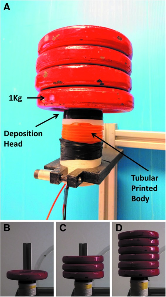
(A) An overall view of the lifting setup for evaluating the root structure in air under different loads. (B–D) Weights from 1 to 6 kg were applied to the system to evaluate the maximum axial force that the robot can exert.
Robotic root bending in air
The bending capabilities of the system were evaluated under particular constant loads. During the bending, both the tip position and angle continuously change, so we cannot apply a constant load as in the case of the straight growth tests, described in the previous section. We therefore developed a setup based on a pulley (280 mm in diameter) with a rope to add weights (Fig. 12). The robot tip is linked to the shaft of the pulley by means of a solid sliding bar (180 mm length) and a rotary joint. The rotary and sliding point of contact permits the tip to follow its commanded directions without the disturbance of any lateral loads. By adding constant loads to the rope, a constant axial load is transferred to the tip.
FIG. 12.

(A) An overall view of the experimental setup for characterizing the robot bending by differential growth. (B) A constant torque applied to the pulley transmits a constant axial load to the tip during the bending. (CE) Sequential images of growing and bending movements. The robot starts bending on the right, and after ∼20 min, it bends on the left, simulating, for example, the avoidance of an obstacle.
The effect of gravity on the deposition process can be negligible for two main reasons: the system is lightweight (160 g tip included) and at the same time it is internally anchored to the tubular structure that does not permit gravity to affect the deposition process. These tests allowed evaluating the bending angle at different deposition ratios (K). The bending angle was measured using an accelerometer integrated at the tip under an axial load of 1 kg, 200°C extrusion temperature, and K of 8:1, 4:1, 2:1, and 1:1 (Supplementary Video S3).
Robotic root growing in an artificial soil
We performed robotic root growing tests in an artificial granular medium made of polyoxymethylene (POM; Ultraform N2320 003; BASF, Ludwigshafen, Germany) plastic beads (diameter = 4 mm). We selected POM for our trials in soil because it shows low moisture absorption (0.2% under experimental conditions at T = 25°C and 40% relative humidity) and thus guarantees repeatable results.
The mechanical strength of this medium was previously tested using standard methods.27 In this medium, we measured an average maximum force of 38.4 N (±4.3 N standard deviation on nine trials) to obtain a vertical penetration to a depth of 200 mm, with a tip diameter of 50 mm and a 60 mm/min speed. The tests were performed in a cubic container of 500 × 1000 mm with a 300 mm depth. The root was fixed to a side of the soil container (Fig. 13A), and an accelerometer embedded in the root tip tracked the tip bending during the experiment. After each experiment, the soil was removed (Fig. 13B) to verify the effective position of the tip and the shape of the built root (Supplementary Video S4).
FIG. 13.

Setup for testing the robotic root growth in a granular soil. (A) A container (500 × 1000 × 300 mm3) was filled with POM, and the robot was fixed to the container wall. (B) View of the robotic root at the end of the growth process. The exact position of the robot was evaluated by removing the soil granules. POM, polyoxymethylene.
Discussion
In our previous work,26,27 we partially translated the efficiency of natural root movement, when growing in soil, to artificial devices. Although these seminal works introduced for the first time the concept of a robot that self-creates its body through a layer-by-layer deposition, the manufacturing process and material used did not allow the implementation of more complex behaviors, such as bending in air and soil following or escaping from external stimuli or avoiding obstacles. In the present work, we introduced a customized FDM 3D printer-based mechanism inside the robot root body. This manufacturing solution, coupled with the choice of using the commercially available PLA as the deposition material, allowed us to obtain a robot that can build its own structure by a fused deposition process of new layers and, at the same time, grow and bend. We demonstrated such root-like robot abilities both in air, by applying external loads to the tip, and in an artificial medium.
We found that a lower temperature (180°) results in a higher layer thickness and consequently higher growing speed, while a higher temperature (200°) results in a more strongly built structure. We found that the thickness of the root tubular structure, in addition to being caused by the settings of the deposition process, is also the result of external forces applied to the root. The larger the external force, the thinner the layer thickness and wider the layer width. This means that, depending on the soil compactness and extrusion temperature, the system can automatically grow faster in loose soils and slower in harder soil while having a thicker root wall and stronger structure for overcoming the soil pressure in harder soils. Therefore, tuning the temperature on the basis of the soil impedance could be a strategy to optimize the growth speed.
A similar swelling behavior is observed in living roots facing with hard soils: a plant root expands its diameter in harder soils while its penetration speed decreases; vice versa, in loose soils a root grows faster with smaller diameter.35 Some hypotheses explain that the radial expansion of impeded root apexes can reduce the axial stress on the root cap,36 and the root swelling produces soil tensile failure that may propagate a crack ahead of the root apex. The generated crack minimizes resistance to the elongating root resulting in an accelerated elongation into this zone of reduced soil strength.37,38 The developed system can overcome a 6 kg axial load (which is equivalent to 0.37 atm of pressure with this root dimension). On increasing the weight, the growing mechanism begins to become unstable due to the increasing friction between the deposition head and deposited layers.
This capacity is not the limitation of the proposed concept and it can be overcome using stronger DC motors, since they are commercially available. In real soil, the system would be able to penetrate till the environmental pressure is less than the maximum pressure that the system can generate. Effective penetration depends on soil types. A positive aspect is that normally the soil pressure increases till a certain depth (few tens of centimeters) and after that the interaction of soil granules prevents the pressure transmission from upper to lower layers.39 However, there are other technical issues that limit the current robot version in performing deep penetration (e.g., crack of PLA filament, longer power lines that cause an increasing loss of energy, and friction of the filament along the wall structure that increases the resisting force to the penetration).
The robot was able to successfully exhibit steering behavior by bending both in air and artificial soil. In air, for smooth curvatures (K = 8:1, 4:1, and 2:1), the model and the experimental data fit (Fig. 7). However, with a higher K (1:1), the effective bending is less than the predicted value. This is due to the mechanical constraints because this ratio overcomes the minimum bending radius of the structure (100 mm), and the internal contact/friction of the growing mechanism components with the structure decreases the effective bending of the tip. In soil, the bending speed obtained was 0.92°/min different from that obtained in air, where under the same conditions, the bending speed was 1.1°/min. This difference is mainly due to the effect of the lateral pressure present in soil that must be overcome for the whole tip to perform bending.
This results in a decrement of the effective bending speed. Moreover, the bending tests performed in the artificial soil showed a very high linearity with respect to that obtained in air (Fig. 8). This result could be due to the peripheral support that the soil can provide for the printed structure, while in air, the structure grows like a beam under an axial load, even if the load at the tip was axially applied.
The velocity of the system, in addition to being governed by the deposition parameters and environmental conditions, was also limited by the overheating of the controller unit and mechanical components. Even if the heater is insulated in Kapton tape and encapsulated in a PTFE structure, after some minutes (approximately 10–15 min, depending also on the environmental conditions), the heat is transferred to other parts of the system, creating problems in the electronic components (when the temperature exceeds 90°C) and mainly in the feeding part, where the filament becomes prematurely soft and thereafter cannot be pushed properly into the extruder.
To avoid this problem, we adopted two solutions: (1) a system shutdown every 10 min for approximately the same amount of time to permit the root to autonomously decrease the whole temperature and (2) an air cooling system located at the top of the root, where the amount of air is regulated to maintain a root temperature on the order of 75°, which is a working temperature (experimentally verified) that assures long and stable system operation. This problem can also be overcome by using polymers with a lower melting temperature shaped in the form of 3D printer filaments.
This work paves the way for a new generation of robots to grow. A distinctive aspect of this robot is its mimicking of the movement ability of plant roots by growing. In general, different types of additive manufacturing solutions can be used to develop and grow robots, including the delivery of raw material to the growing zone (root tip), the plotting strategy, and the fusion methods. The robotic root tubular structure generated by the growing process can be useful for the transmission of building material(s) and energy-supplier solutions to the growing root. This tubular structure can also provide interesting solutions for several applications, including transmitting data from a sensorized tip in soil-monitoring tasks and passing oxygen, drugs, or food in rescue scenarios and cameras or surgical tools for medical applications.
Supplementary Material
Acknowledgment
This study was partially founded by the PLANTOID project (EU-FP7-FETOpen grant no. 29343).
Author Disclosure Statement
No competing financial interests exist.
References
- 1.Pfeifer R, Lungarella M, Iida F. Self-organization, embodiment, and biologically inspired robotics. Science 2007;318:1088–1093 [DOI] [PubMed] [Google Scholar]
- 2.Kim S, Laschi C, Trimmer B. Soft robotics: a bioinspired evolution in robotics. Trends Biotechnol 2013;31:287–294 [DOI] [PubMed] [Google Scholar]
- 3.Laschi C, Cianchetti M. Soft robotics: new perspectives for robot bodyware and control. Front Bioeng Biotechnol 2014;2:3. [DOI] [PMC free article] [PubMed] [Google Scholar]
- 4.Rus D, Tolley MT. Design, fabrication and control of soft robots. Nature 2015;521:467–475 [DOI] [PubMed] [Google Scholar]
- 5.Mazzolai B, Mattoli V. Robotics: generation soft. Nature 2016;536:400–401 [DOI] [PubMed] [Google Scholar]
- 6.Wang L, Iida F. Deformation in soft-matter robotics: a categorization and quantitative characterization. IEEE Robot Autom Mag 2015;22:125–139 [Google Scholar]
- 7.Manti M, Cacucciolo V, Cianchetti M. Stiffening in soft robotics: a review of the state of the art. IEEE Robot Autom Mag 2016;23:93–106 [Google Scholar]
- 8.Robinson G, Davies JBC. Continuum robots–a state of the art. In: Robotics and Automation 1999, IEEE International Conference 1999;4:2849–2854 [Google Scholar]
- 9.Trivedi D, Rahn CD, Kier WM, Walker ID. Soft robotics: Biological inspiration, state of the art, and future research. Appl Bionics Biomech 2008;5:99–117 [Google Scholar]
- 10.Walker ID. Continuous backbone “continuum” robot manipulators. ISRN Robotics 2013;1–19 [Google Scholar]
- 11.Heckele M. Schomburg WK. Review on micro molding of thermoplastic polymers. J Micromech Microeng 2003;14:R1 [Google Scholar]
- 12.Qin D, Xia Y, Whitesides GM. Soft lithography for micro-and nanoscale patterning. Nat Protoc 2010;5:491–502 [DOI] [PubMed] [Google Scholar]
- 13.Wu W, DeConinck A, Lewis JA. Omnidirectional printing of 3D microvascular networks. Adv Mater 2011;23:24. [DOI] [PubMed] [Google Scholar]
- 14.Wang L, Brodbeck L, Iida F. Mechanics and energetics in tool manufacture and use: a synthetic approach. J R Soc Interface 2014;11:20140827. [DOI] [PMC free article] [PubMed] [Google Scholar]
- 15.Laschi C, Mazzolai B. Lessons from animals and plants: the symbiosis of morphological computation and soft robotics. IEEE Robot Autom Mag 2016;23:107–114 [Google Scholar]
- 16.Laschi C, Mazzolai B, Cianchetti C. Soft robotics: technologies and systems pushing the boundaries of robot abilities. Sci Robotics 2016;1:eaah3690. [DOI] [PubMed] [Google Scholar]
- 17.Wang L, Culha U, Iida F. A dragline-forming mobile robot inspired by spiders. Bioinspir Biomim 2014;9:016006. [DOI] [PubMed] [Google Scholar]
- 18.Hirose S, Hiroya Y. Snake-like robots. IEEE Robot Autom Mag 2009;16:88–98 [Google Scholar]
- 19.Kotay K, Rus D. The inchworm robot: a multi-functional system. Auton Robots 2000;8:53–69 [Google Scholar]
- 20.Menciassi A, Dario P. Bio-inspired solutions for locomotion in the gastrointestinal tract: background and perspectives. Philos Trans A Math Phys Eng Sci 2003;361:2287–2298 [DOI] [PubMed] [Google Scholar]
- 21.Phee L, Accoto D, Menciassi A, Stefanini C, Carrozza MC, Dario P. Analysis and development of locomotion devices for the gastrointestinal tract. IEEE Trans Biomed Eng 2002;49:613–616 [DOI] [PubMed] [Google Scholar]
- 22.Lim J, Park H, An J, Hong YS, Kim B, Yi BJ. One pneumatic line based inchworm-like micro robot for half-inch pipe inspection. Mechatronics 2008;18:315–322 [Google Scholar]
- 23.Koh JS, Cho KJ. Omegabot: Biomimetic inchworm robot using SMA coil actuator and smart composite microstructures (SCM). In: Robotics and Biomimetics (ROBIO), 2009. IEEE International Conference 2009;1154–1159 [Google Scholar]
- 24.Omori H, Nakamura T, Yada T. An underground explorer robot based on peristaltic crawling of earthworms. Ind Robot 2009;36:358–364 [Google Scholar]
- 25.Mazzolai B, Beccai L, Mattoli V. Plants as model in biomimetics and biorobotics: new perspectives. Front Bioeng Biotechnol 2014;2:2. [DOI] [PMC free article] [PubMed] [Google Scholar]
- 26.Sadeghi A, Tonazzini A, Popova L, Mazzolai B. Robotic mechanism for soil penetration inspired by plant root. In Robotics and Automation (ICRA), 2013 IEEE International Conference 2013;3457–3462 [Google Scholar]
- 27.Sadeghi A, Tonazzini A, Popova L, Mazzolai B. A novel growing device inspired by plant root soil penetration behaviors. PloS One 2014;9:e90139. [DOI] [PMC free article] [PubMed] [Google Scholar]
- 28.Baluška F, Mancuso S, Volkmann D, Barlow PW. Root apex transition zone: a signaling-response nexus in the root. Trends Plant Sci 2010;15:402–408 [DOI] [PubMed] [Google Scholar]
- 29.Blancaflor EB, Masson PH. Plant gravitropism. Unraveling the ups and downs of a complex process. Plant Physiol 2003;133:1677–1690 [DOI] [PMC free article] [PubMed] [Google Scholar]
- 30.Hart JW. Gravitropism. Plant tropisms and other growth movements. Springer Science & Business Media, 1990;44:89 [Google Scholar]
- 31.Takahashi N, Yamazaki Y, Kobayashi A, Higashitani A, Takahashi H. Hydrotropism interacts with gravitropism by degrading amyloplasts in seedling roots of Arabidopsis and radish. Plant Physiol 2003;132:805. [DOI] [PMC free article] [PubMed] [Google Scholar]
- 32.Ding JP, Pickard BG. Modulation of mechanosensitive calcium‐selective cation channels by temperature. Plant J 1993;3:713–720 [PubMed] [Google Scholar]
- 33.Sadeghi A, Mondini A, Del Dottore E, Mattoli V, Beccai L, Taccola S, et al. A plant-inspired robot with soft differential bending capabilities. Bioinspir Biomim 2016;12:015001. [DOI] [PubMed] [Google Scholar]
- 34.Taccola S, Greco F, Sinibaldi E, Mondini A, Mazzolai B, Mattoli V. Toward a new generation of electrically controllable hygromorphic soft actuators. Adv Mater 2015;27:1668–1675 [DOI] [PMC free article] [PubMed] [Google Scholar]
- 35.Bengough AG, Bransby MF, Hans J, McKenna SJ, Roberts TJ, Valentine TA. Root responses to soil physical conditions; growth dynamics from field to cell. J Exp Bot 2006;57:437–447 [DOI] [PubMed] [Google Scholar]
- 36.Bengough AG, Mullins CE. Mechanical impedance to root growth: a review of experimental techniques and root growth responses. Eur J Soil Sci 1990;41:341–358 [Google Scholar]
- 37.Materechera SA, Dexter AR, Alston ML. Penetration of very strong soils by seedling roots of different plant species. Plant Soil 1991;135:31–41 [Google Scholar]
- 38.Popova L, Van Dusschoten D, Nagel KA, Fiorani F, Mazzolai B. Plant root tortuosity: an indicator of root path formation in soil with different composition and density. Ann Bot 2016;118:685–698 [DOI] [PMC free article] [PubMed] [Google Scholar]
- 39.Huang W, Sheng D, Sloan SW, Yu HS. Finite element analysis of cone penetration in cohesionless soil. Comput Geotech 2004;31:517–528 [Google Scholar]
Associated Data
This section collects any data citations, data availability statements, or supplementary materials included in this article.