Abstract
Cryopreservation by vitrification is the only promising solution for long-term organ preservation which can save millions of lives across the world. One of the challenges in cryopreservation of large-size tissues and organs is to prevent fracture formation due to the tendency of the material to contract with temperature. The current study focuses on a pillow-like shape of a cryobag, while exploring various strategies to reduce thermo-mechanical stress during the rewarming phase of the cryopreservation protocol, where maximum stresses are typically found. It is demonstrated in this study that while the level of stress may generally increase with the increasing amount of CPA filled in the cryobag, the ratio between width and length of the cryobag play a significant role. Counterintuitively, the overall maximum stress is not found when the bag is filled to its maximum capacity (when the filled cryobag resembles a sphere). Parametric investigation suggests that reducing the initial rewarming rate between the storage temperature and the glass transition temperature may dramatically decrease the thermo-mechanical stress. Adding a temperature hold during rewarming at the glass transition temperature may reduce the thermo-mechanical stress in some cases, but may have an adverse effect in other cases. Finally, it is demonstrated that careful incorporation of volumetric heating by means on nanoparticles in an alternating magnetic field, or nanowarming, can dramatically reduce the resulting thermo-mechanical stress. These observations display the potential benefit of a thermo-mechanical design of the cryopreservation protocols in order to prevent structural damage.
Keywords: Cryopreservation, vitrification, nanowarming, thermo-mechanical stress, simulations, cryobag
Introduction
Cryopreservation is a technique to store biological materials at very low temperatures for a potentially indefinite period of time, with applications to transplant and regenerative medicine. Cooling of any biomaterial below the freezing point can be harmful and cryopreservation success is dependent on two key ingredients: (a) cryoprotective agents (CPAs) to control and possibly circumvent ice formation, and (b) appropriate thermal history to minimize a host of devastating effects associated with toxicity, biotransport phenomena, and thermo-mechanical stress.
Cryopreservation success is also dependent on the size of the specimen. Not without technological challenges, cryopreservation success in small specimens (µm to mm size) is relatively high, where the biological system is less complex and homogeneous conditions are more easily obtained across the specimen. That includes cryopreservation of stem cells [4], [19], corneas [2], [3] and pancreatic islets [23], [24]. However, cryopreservation of large-size specimens remains an unmet need, where size-scaling from small specimens to bulky tissues and organs presents additional challenges [25].
Many of the challenges in cryopreservation of large specimens originate from principles of heat and mass transfer. In particular, large specimens experience non-uniform thermal histories, which may lead to variable vulnerability to toxicity effects, the formation of ice, and the development of thermo-mechanical stress due to differential thermal expansion [5], [10], [32] (thermo-mechanical stress and thermal stress are used interchangeably in this study). Frequently, such stresses exceed the strength of the biomaterial and it undergoes irreversible structural changes [33], [39].
The only viable alternative to eliminate the devastating effects of ice crystallization in cryopreservation of large specimens is vitrification (vitreous in Latin means glassy). Vitrification benefits from the exponential increase of the viscosity of the CPA solution with the decreasing temperature at high cooling rates. When the CPA-permeated specimen and its surrounding solution are cooled rapidly to very low temperatures, such that the molecules of the CPA cocktail do not have enough time to rearrange and form crystals, the specimen is trapped in an amorphous (glassy) state [14]. The temperature below which the material’s viscosity is so high that it becomes metastable is known as the glass transition temperature, where the material can be considered as a solid for all practical applications.
In order to prevent rewarming-phase crystallization (RPC) of the metastable CPA-tissue system during recovery from cryogenic storage, rapid heating rates are also necessary [27]. Here RPC may generally relate to ice nucleation and growth in the glassy state or during rewarming (devitrification) or crystal growth from nuclei and small crystals already trapped in the amorphous material during cooling [26]. Either way, the absolute value of the critical rewarming rate to prevent RPC is much higher than that of the critical cooling rate to facilitate vitrification [27], [37].
While the increasing cooling and rewarming rates are favorable to prevent crystallization in different ways, they may intensify thermo-mechanical stresses [38]. Furthermore, it has been shown that the thermo-mechanical stress is path-dependent, and the entire thermal history must be considered when the instantaneous level of mechanical stress is evaluated [10]. In particular, the early stage of rewarming has been identified as most dangerous to fracturing and structural damages [10], [29], [30], [31]. Either way, while hazardous levels of mechanical stress may always develop below the glass transition temperature, this temperature range may extend to several degrees above this temperature threshold, proportionally to the cooling and rewarming rates [32].
An alternative approach to reduce thermo-mechanical stress during rewarming is volumetric heating, rather than relying solely on rewarming by means of convective heating to the surface of the specimen. Volumetric heating can potentially increase the overall rewarming rate, while moderating temperature gradients within the specimen. Previous experimental studies have explored the feasibility of volumetric heating by means of electromagnetic radiation in the radio frequency (RF) range [13], [35] while some studies focused on the microwave range [6], [7], [18], [22], [36], [40], benefiting from its readily accessible commercial technology. While microwave and wider RF-range applications may benefit cryopreservation applications, they are also associated with so-called hot spots, due to inhomogeneity in the electrometric-field intensity [13], [34]. A recent experimental study explored the possibility of improving cryopreservation by means of heating of magnetic nanoparticles in an RF field (termed nanowarming) [12]. Here the RF heating primarily heats volumetrically distributed nanoparticles (i.e., nanowarmers), which in turn conduct heat to their immediate surroundings; direct heat generation in the specimen due to RF heating is negligible in nanowarming applications [12].
This study aims to explore thermo-mechanical effects during cryopreservation protocols in common cryogenic bags. This study targets the tri-dimensional (3D) characteristics of pillow-like shaped cryobags, while expanding upon a two-dimensional (2D) analysis of simplified geometries [10], [11]. In particular, this study makes use of already established physical modeling [10], [11], [32], [39] and a finite elements analysis (FEA) commercial code to demonstrate that thermo-mechanical stresses can be reduced, and possibly eliminated, by carefully planning the cryopreservation protocol. This study further explores the potential benefits of nanowarming in cryopreservation by vitrification in cryobags.
Mathematical Formulation
Consistent with previous studies [10], [11], [15], it is assumed that heat generation due to viscous dissipation is negligible when compared with heat exchange between the specimen and its cryogenic surroundings and with the heat generated due to nanowarming. This assumption permits decoupling the thermo-mechanical stress problem in the following way [10]. The heat transfer problem is solved first, independent of the field of stress. Next, the mechanical stress problem is solved, with the transient temperature field serving as an input for calculating the corresponding thermal strain history.
Heat Transfer Model
Within the temperature range relevant to development of thermo-mechanical stresses, the material has a very high viscosity and essentially behaves like a solid for all practical purposes. In this temperature range, heat is assumed to be transferred solely by conduction [10]:
| (1) |
where C is the volumetric specific heat, T is the temperature, k is the thermal conductivity, and q is heat generated due to nanowarmers [11], and the dot above symbols represents a time derivative.
Heat transfer between the cryobag surface and the cryogenic surroundings is assumed to be due to the combined effect of convection and radiation:
| (2) |
where n̂ is the normal to the cryobag surface, h is the effective heat transfer coefficient by convection and radiation to the cryogenic surroundings, and the subscripts s and ∞ refer to the cryobag surface and the cryogenic environment respectively.
Solid Mechanics Model
The vitrifying CPA is modelled as a Maxwell fluid, where the total strain rate is the sum of creep, elastic, and thermal strain rates [10], [32]:
| (3) |
The creep strain rate is given by:
| (4) |
where S is the deviatoric stress tensor and η is the viscosity. The deviatoric stress tensor is what actually causes distortion of the body, which is the stress tensor left after subtracting out the hydrostatic stress.
The elastic strain rate is given by:
| (5) |
where E is the elastic modulus, ν is the Poisson ratio, I is the identity matrix, and tr is the trace of a matrix.
The thermal strain rate is defined by:
| (6) |
where β is the linear thermal expansion coefficient.
Geometric Model
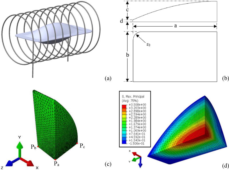
A pillow-like shape is assumed for the cryobag in the current study as illustrated in Fig. 1. The range of cryobag dimensions selected for this study is typical for large-size cryopreservation, Table 1. In particular, an overall length of 122 mm was selected (2a in Fig. 1(b)), which may be used, for example, for cryopreservation of human heart valves and kidneys [38]. Since the mechanical stress is expected to increase with the size of the cryobag, the current parametric study includes variable width ratios (b/a) and cryobag filling ratios (c/a), ranging up to 1, with the upper boundary values resembling a spherical shape.
Figure 1.
The cryobag model: (a) illustration of the geometric model with coils representing electromagnetic induction heater; (b) geometric parameters used in the current study, where only 1/8 of the model is simulated due to symmetry; (c) finite elements mesh rendering including three representative points used in the current study, where Pa is the volumetric center, Pb is the center of longest cryobag edge, and Pc is the center of the bag’s surface; and (d) a representative stress distribution with the maximum stress at the center of the cryobag and minimum stress at the outer surface.
Table 1.
Geometric parameter ranges used in the analysis of the pillow-shape cryobag illustrated in Fig. 1.
| a (mm) |
Width Ratio, b/a |
Filling Ratio, c/a (bag volume in cc) | d (mm) |
r0 (mm) |
|---|---|---|---|---|
| 61.0 | 0.2 | 0 (0.53), 1/6 (3.63), 1/3 (6.73), 1/2 (9.8), 2/3 (12.9), 5/6 (16.0), 1 (19.1) | 0.5 | 2.0 |
| 0.4 | 0 (1.05), 1/6 (7.25), 1/3 (13.5), 1/2 (19.7), 2/3 (25.9), 5/6 (32.1), 1 (38.3) | |||
| 0.6 | 0 (1.58), 1/6 (10.8), 1/3 (20.2), 1/2 (29.4), 2/3 (38.8), 5/6 (48.1), 1 (57.4) | |||
| 0.8 | 0 (2.02), 1/6 (14.5), 1/3 (26.9), 1/2 (39.3), 2/3 (51.7), 5/6 (64.1), 1 (76.5) | |||
| 1.0 | 0 (2.63), 1/6 (18.1), 1/3 (33.6), 1/2 (49.2), 2/3 (64.7), 5/6 (80.2), 1 (95.7) |
A base thickness of 1 mm (2d in Fig. 1(b)) is added to the pillow geometry in the z direction in order to approximate the soldered region of the cryobag, which is assembled from two sheets of a thin, flexible material, such as fluorinated ethylene propylene (FEP) (KryoVue Cryopreservation Peel Pouch, American Fluoroseal Corp., Gaithersburg, MD, USA). This base thickness is essential to prevent a singularity in stress calculations at the soldered edge, which otherwise would yield unrealistically high stresses. For similar reasons the radius at the corner of the cryobag, r0, was selected to be 2 mm.
The cryobag is typically made out of a highly compliant thin-sheet material, which may retain its flexibility at extremely low temperatures. Hence, the constraining effect of the wall on the developing thermo-mechanical stress is initially neglected in the analysis presented below, and the cryobag wall is omitted from the illustration in Fig. 1. Once the worst-case stress scenario is identified for the case of an extremely compliant cryobag, the assumption related to the wall effect is revisited.
With the above considerations in mind, the curved surface of the material contained in the cryobag is modeled by:
| (7) |
where only a one-eighth of the shape is illustrated in Fig. 1 due to symmetry considerations. Therefore, an eighth geometric pillow model is used for the analysis by applying the appropriate symmetric boundary conditions.
Figure 1(c) displays the finite element discretization of the CPA domain, generated by the commercial finite element analysis (FEA) code ABAQUS (Dassault Systems, Inc.). The thermo-mechanical stress problem was solved using ABAQUS. In total, between 50,000 and 60,000 10-node quadratic tetrahedron elements were used, depending on the selected case (DC3D10 for heat transfer analysis and C3D10H for stress analysis). In practice, element meshing was performed parametrically, with a decreasing mesh size on the x-y plane towards the center of the cryobag where stress is maximum. The mesh size was kept uniform in the z direction, as stress and temperature gradients may become very significant in this direction with the decreasing CPA volume. An element number convergence study was performed for each bag geometry, which yielded a typical element dimension at the center of the domain ranging from 0.07 mm for the smallest volume (c/a=0.016, b/a=0.2) to 1 mm for the largest volume (c/a=1, b/a=1). Respectively, the typical dimension of elements at the edge of the bag ranged from 1 mm to 3 mm. Automatic time stepping was chosen with two constraints: (i) less than 1°C, and (ii) less than 1% in maximum inelastic strain rate change between every two consecutive steps at any given node in the domain.
Materials
The material properties used for the analysis are listed in Table 2. Consistent with recent experimental [12], [33], [37], [39] and theoretical studies [10], [11], the CPA cocktail VS55 is used as a model for material properties. VS55 is a cocktail of 3.1 M dimethyl sulfoxide (DMSO), 2.2 M propylene glycol, and 3.1 M formamide. While this study uses VS55 as a model, the results presented in this study are quite general and relevant to a large selection of vitrification solutions.
Table 2.
Material properties used in this study.
| Property | Material | ||||
|---|---|---|---|---|---|
|
| |||||
| VS55 | Cryobag | ||||
| Viscosity, Pa·s | 1.21×10⁴ | −100°C≤T | [28] | N/A | |
| 4.2783×10⁻²³ e−0.6071 T | −140°C≤T<−100°C | ||||
| 4.63×10¹⁴ | T≤−140°C | ||||
|
| |||||
| Glass transition temperature, Tg | −123°C | [28] | N/A | ||
|
| |||||
| Density | 1100 kg/m3 | [1] | 2150 kg/m3 | [8] | |
|
| |||||
| Thermal conductivity | 0.3 W/m °C | [9] | 0.2 W/m °C | [8] | |
|
| |||||
| Specific heat | 2400 J/kg °C | [41] | 268 J/kg °C | [8] | |
|
| |||||
| Thermal Expansion coefficient | 1.1×10⁻⁴ 1/°C | [10] | 1.1×10−41/°C | [8] | |
|
| |||||
| Young’s modulus | 0.8 GPa | [20], [21] | 0.46 GPa | [8] | |
|
| |||||
| Poisson’s ratio | 0.25 | [10] | 0.48 | [8] | |
For the case including volumetric heating by means of nanoparticles, the heat generation rate in W/m3 is calculated by:
| (8) |
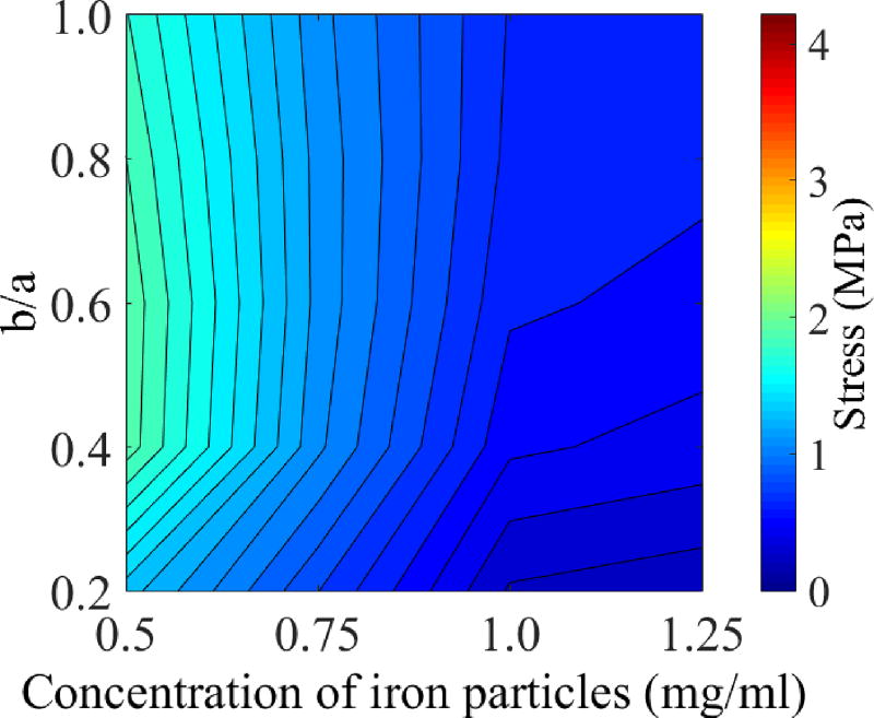
where SAR is the specific absorption rate for VS55 mixed with Fe203 nanoparticles and excited at a field strength of 20 kA/m and frequency of 360KHz [11], and Cn is the concentration of nanoparticles. Eisenberg et al. [11] have analyzed a 2D case of nanoparticle heating at a concentration of 5.0 mg/ml, which yielded an average rewarming rate of 40°C/min at the volumetric center. In order to decrease thermal stress in the 3D case, the current study focuses on lower concentrations in the range of 0.5 mg/ml to 1.25 mg/ml, as discussed in the Results and Discussion section. It is assumed that the specific absorption rate of the mixture is independent of the concentration of nanoparticles in this low concentration range.
Cryogenic Protocol
Consistent with a previous study [11], the overall heat transfer coefficient is kept constant at 150 W/m2K, which is a representative value of the forced convection condition in a controlled-rate cooler [16]. Note that the radiative heat transfer in these conditions is less than 1% of the overall heat transfer coefficient.
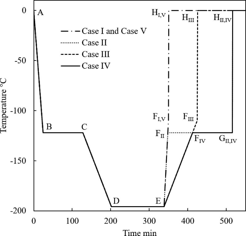
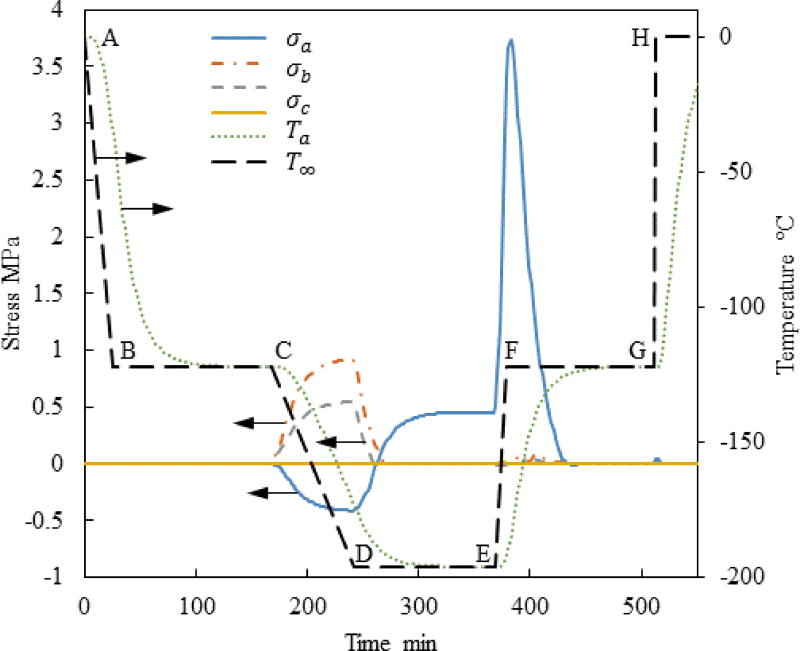
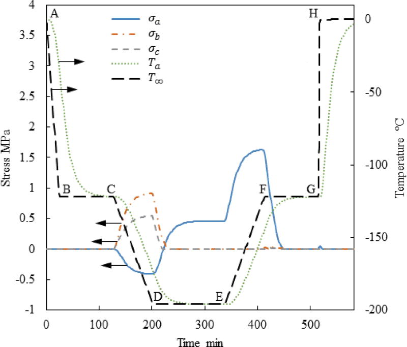
The typical thermal history analyzed in this study consists of six segments, as illustrated for Case I in Fig. 2: (A–B) fast initial cooling to avoid crystallization, in a temperature range characterized by relatively low viscosity; (B–C) temperature hold to facilitate annealing when the viscosity value reaches a significantly high value; (C–D) slow cooling to the cryogenic storage temperature to minimize thermal stress, passing through the glass transition temperature—a temperature threshold below which the amorphous material may be considered solid for all practical applications; (D–E) constant temperature hold at the storage temperature, potentially indefinitely; (E–F) slow rewarming to minimize thermal stress; and (F–H) final rapid heating at a rate that exceed the critical rewarming rate to suppress RPC (G–H). In Cases II and IV in Fig. 2, an additional temperature hold is added to the thermal protocol (F–G) to explore the possibility of an additional annealing stage before the rapid rewarming through the critical temperature range for RPC (G–H). Common cryopreservation practice most frequently excludes segment B–C [10], while segment F–G is included in the current study for the first time.
Figure 2.
Thermal histories in the controlled-rate cooling chamber investigated in the current study.
The current study focuses on the rewarming phase of the cryogenic protocol, where a common thermal history was selected for all cases up to point E in Fig. 2 [10]: (A–B) constant cooling rate of 5°C/min; (B–C) temperature hold at −122°C, which is 1°C above the glass transition temperature, Tg, for VS55; (C–D) constant cooling rate of 1°C/min; and (D–E) storage temperature at −196°C, which is the boiling temperature for liquid nitrogen. In Case I, which is the benchmark case [10], the rewarming phase is characterized by two segments: initial rewarming rate of 7.5°C/min up to −110°C (E–F), followed by a rapid rewarming rate of 100°C/min.
Case II deviates from Case I by including a temperature hold period (F–G) at the same temperature as of the annealing stage during cooling (B–C). The rationale for the additional hold period during rewarming is to ensure that no portion of the vitrified domain will experience cooling rates higher than 7.5°C/min, when the material is prone to destructive thermo-mechanical stresses. Cases III and IV are similar to Cases I and II, respectively, excepting that the initial warming rate is reduced to 1°C/min, which reduces the thermal stress when the material is most prone to structural damage. While Cases I through IV assume convective rewarming solely, Case V is similar to Case I with the inclusion of volumetric heating by means of nanoparticles.
The duration of the respective temperature hold stages was varied according to the cryobag volume, to ensure thermal equilibrium before advancing to the next stage of the cryogenic protocol. Thermal equilibrium was approximated as temperature variations of less than 10−6 °C/min.
Results and Discussion
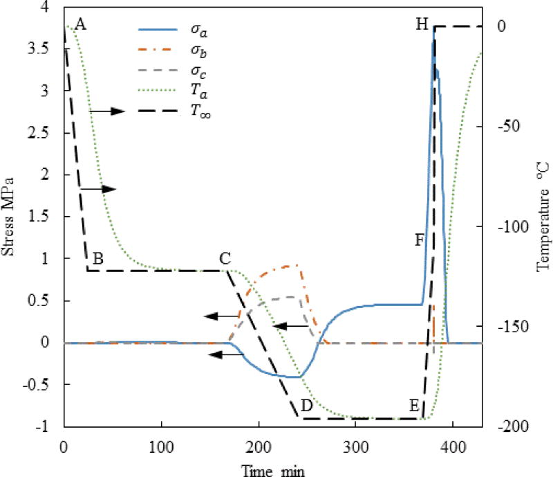
Figure 3 displays the thermal history and the maximum principle stress history in the strategic points illustrated in Fig. 1(c) for Case I where a=61 mm, c/a=0.5 and b/a=0.4. This set of a, b, and c dimensions represents a possible geometry for a cryobag used for heart valve cryopreservation. Nonetheless, the range of a, b, and c values investigated in this study is much wider, covering a wide range of cryopreservation applications. Points Pa, Pb, and Pc were selected based on the results of a previous study [10], where the maximum stress is suspected. Note that the current study aims at identifying the conditioning to fracture, after which the specimen becomes useless for cryopreservation. At the same token, this study is not aimed at exploring solid mechanics effects after the onset of fracturing at some point in the domain. Since brittle materials, such as glasses, tend to fail under tension [17], only the maximum principle stress is presented for each geometric point; when it has a positive value it means tension, while a negative value means compression.
Figure 3.
Thermal history and maximum principle stress histories at the points specified in Fig. 1 for Case I where a=61mm, c/a=0.5, and b/a=0.4.
It can be seen from Fig. 3 that no significant stress develops during the initial stage of cooling, since the viscosity is very low and the material is free to flow as a liquid. The temperature hold B–C is designed to facilitate thermal equilibrium at an intermediate stage, only 1°C above the glass transition temperature. Significant stresses start to build up immediately after point C, when the viscosity value becomes so significant that the material start to gain a solid-like behavior.
Only an insignificant stress level is observed at points b and c in Fig. 3 after thermal equilibrium at cryogenic storage (later times along segment D–E). The maximum principle stress at point a at the same time period is subcritical but not insignificant. In general, the strength of the vitrified material is of the order of a few MPa, depending on the specific CPA composition; 3.2 MPa has been suggested as the stress-to-fracture for a closely related reference solution of 7.05M DMSO [32], [39]. One should be careful to not misinterpret these relatively low stresses at cryogenic storage as the outcome of stress relaxation, as this effect could not have happened well below the glass transition temperature.
The cause for the low stress at cryogenic storage in Fig. 3 is hidden in the integration of the hold-temperature segment B–C into the cryogenic protocol [10,11]. During that time, the material is free to flow as a liquid while the temperature distribution across the bag equilibrates, resulting in zero stress distribution. Temperature gradients across the bag start to form again once cooling commences beyond point C, where the material starts to behave as solid almost immediately thereafter. The temperature gradients during the second segment of cooling (C–D) give rise to mechanical stresses due to the increase in thermal strain rates, Eq. (6), while the ability of the strain to creep away diminishes with the exponentially increasingly (and already very high) viscosity around glass transition, Eq. (4). Once thermal equilibration is regained at cryogenic storage, the thermal strain distribution across the CPA becomes uniform, which again results in lower stresses.
The main reasons for the non-uniform thermo-mechanical stress at cryogenic storage can be attributed to (i) the gradual glass transition across the bag subject to temperature gradients, and (ii) the thermal expansion mismatch between the CPA and the bag, or more generally between the CPA and the container [39]. More moderate cooling rates in segment C–D have shown to further decrease the residual stress at the storage temperature [11]. Mechanical stress due to thermal expansion mismatch between the CPA and the container can be reduced by selecting container materials with similar thermal expansion to that of the CPA. This stress can be reduced further by selecting container materials characterized by a higher compliance [32]. Either way, the integration of segment B–C and the design of segment C–D illustrates the potential benefits of computer simulations in the design of cryopreservation protocols.
Note that the maximum stress at Pa changes from compression during cooling to tension during rewarming, as the temperature distribution in the bag reverses (warmest at the center during cooling and coldest at the center during rewarming). The above observation explains why the current study is focused on exploring various rewarming strategies to decrease the maximum principle stress in tension, while the stress during cooling and cryogenic storage can be controlled effectively.
While the maximum principle stress in tension is found at different points in time at the various locations, the maximum overall tensile stress is found at the early stage of rewarming, between its onset and the glass transition temperature; its magnitude is larger than the maximum principle stress in compression. This observation is consistent with previous theoretical [10], [30], [31] and experimental [29] studies.
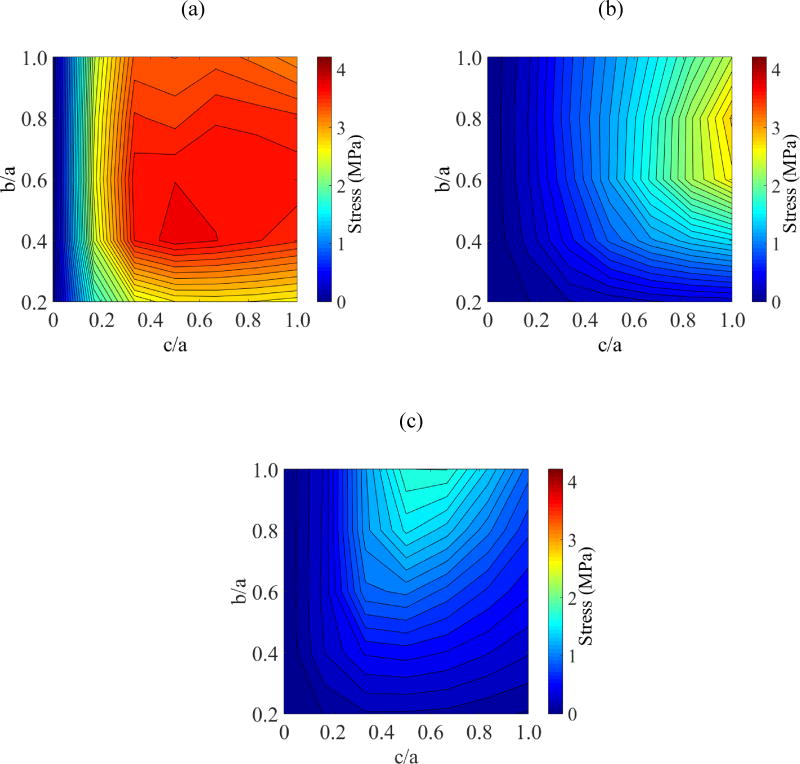
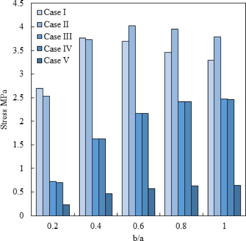
Figure 4 displays parametric study results on the ratio b/a when a=61 mm and c/a=0.5. This study expands on the special case associated with Fig. 3. From Fig. 4 it can be seen that the global maximum principle stress is found at the geometric center of the domain, Pa. The geometric parameters associated with the global maximum principle stress, when c/a is also varied between 0 and 1, are listed in Table 3. When b/a=1 and c/a=1, the cryobag resembles a sphere, while the cryobag resembles a flat plate when c/a is very small. Since the maximum principle stresses at points Pb and Pc are always found during cooling in this study (the same cooling protocols is applied in all studies cases), they are not listed in Table 3. Note that the maximum stress at each point of analysis is found for a different set of geometrical parameters. Further note that the global maximum principle stress is correlated neither with the case resembling a flat plate nor with the case resembling a sphere.
Figure 4.
Parametric study results for Case I: (a) maximum principal stress at the volumetric center, Pa; (b) maximum principal stress at center of longest edge, Pb; and (c) maximum principal stress at center of outer surface, Pc.
Table 3.
Parametric study results for the maximum principle stress during rewarming at Pa where c=61 mm.
| σa,max, MPa | c/a | b/a | ||
|---|---|---|---|---|
| Case I | 3.77 | 0.53 | 0.51 | |
| Case II | 4.18 | 0.64 | 0.70 | |
| Case III | 3.15 | 1.00 | 0.77 | |
| Case IV | 3.16 | 1.00 | 0.77 | |
| Case V | 0.5 mg/ml | 2.00 | * | 0.49 |
| 0.75 mg/ml | 1.17 | * | 0.60 | |
| 1.03 mg/ml | 0.69 | * | 0.96 | |
| 1.25 mg/ml | 0.65 | * | 0.97 | |
c/a=0.5 was kept constant during volumetric heating studies
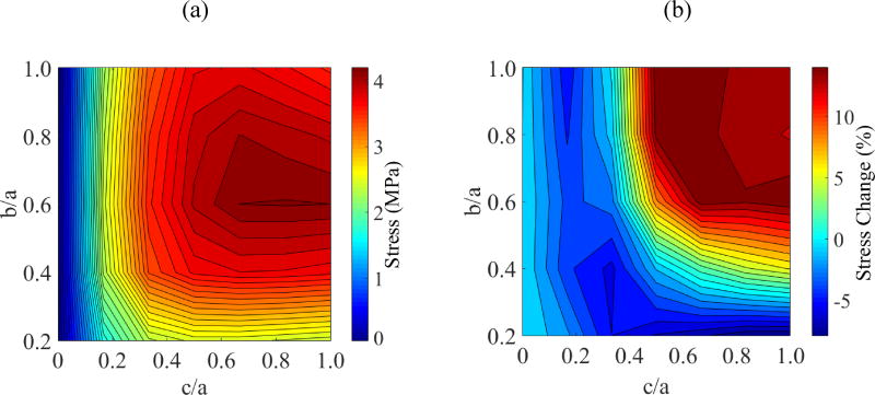
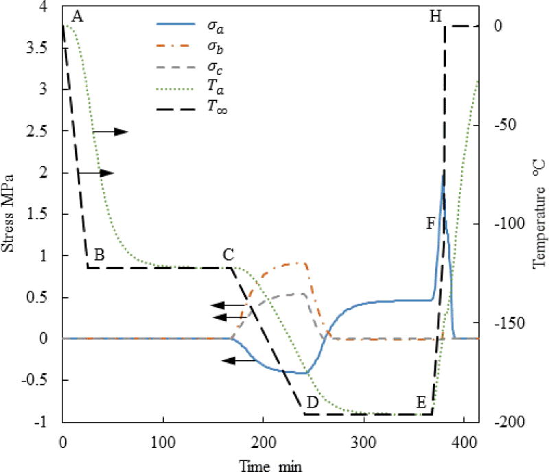
Figure 5 displays the thermal history and the stress history for a case similar to the one presented in Fig. 3, but now with the addition of a temperature hold stage before the final stage of rapid rewarming—Case II. The stress at the onset of rewarming has been decrease in this special case of a=61mm, c/a=0.5, and b/a=0.4. However, a parametric study on the cryobag dimensions indicates that the maximum global principle stress in Case II is actually higher than that in Case I, as can be seen from Fig. 6 and Table 3. Detailed analysis suggests that the maximum principle stress in Case II varies between −7% to +14% when compared with Case I. For example, Case II always yields a worse result than case I when each of the ratios c/a and b/a is greater than 0.5 as displayed in Fig. 6(b).
Figure 5.
Thermal and maximal principle stress history at the points specified in Fig. 1 for Case II where a=61mm, c/a=0.5, and b/a=0.4.
Figure 6.
Results for Case II: (a) Maximum principal stress at center of volume, Pa; and (b) Stress reduction achieved by incorporating a temperature hold period at the glass transition temperature during the thawing stage.
The reason for the counter intuitive observation that an annealing stage during rewarming (Case II) may actually increase stresses is associated with the temperature distribution within the subdomain behaving like a solid and its size. Without such an annealing stage (Case I), the material next to the bag wall quickly warms up above the glass transition temperature, while the size of the subdomain that can support mechanical stresses quickly shrinks. By contrast, the material behaves like a solid for a longer period of time in Case II, while the rewarming rate is slowed down. Two competing effects act during the annealing stage: viscous effects in some portion of the CPA domain may decrease the maximum stress, while a larger CPA volume behaving as a solid may increase the maximum stress. The outcome of the added annealing stage cannot be predicted a priori, which is the result of geometrical parameters and the specific thermal history applied. This stands as one example for how computer simulations can be used to plan cryopreservation protocols to reduce mechanical stress, where the outcome is dependent on the individual case analyzed.
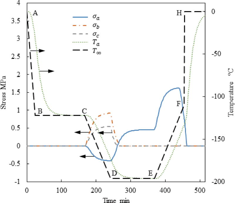
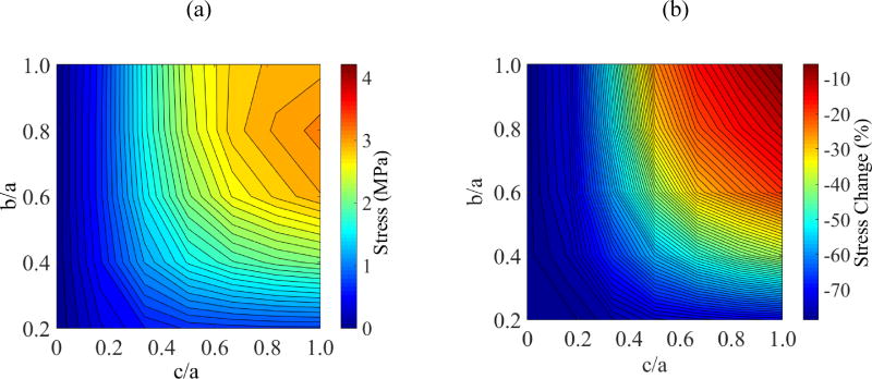
Figure 7 demonstrates the slower initial rewarming rate in Case III (reduced from 7.5°C/min to 1°C/min in stage E–F) can reduce the maximum principle stress for the special geometrical case presented by Figs. 3 and 5. While the maximum global principle stress is still in tension, it is now shifted to a different location, as can be seen from Fig. 8 and Table 3, which is still within the hazardous range that can lead to fracture formation. This observation signifies the need for a multi-parameter optimization of the cryobag shape and thermal protocol, when large-size vitrification is considered.
Figure 7.
Thermal and maximum principle stress history at the points specified in Fig. 1 for Case III where a=61mm, c/a=0.5, and b/a=0.4.
Figure 8.
Results for Case III: (a) Maximum principal stress at center of volume, Pa; and (b) Stress reduction achieved by reducing the rewarming rate from 7.5°C/min to 1°C/min between the storage temperature and the glass transition temperature.
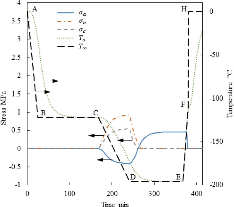
Figure 9 displays the results of Case IV for the same geometrical parameters presented in Fig. 7 for Case III; a temperature hold between slow rewarming and fast rewarming is added in Case IV. Close investigation of the range of geometrical parameters included in this study suggests that the differences in the maximum principle stress are within a 3% range, which suggests that a temperature hold during rewarming may be beneficial only after rapid initial rewarming. However, a temperature hold after slow initial rewarming may add only marginal benefit.
Figure 9.
Thermal and maximum principle stress history at the points specified in Fig. 1 for Case IV where a=61mm, c/a=0.5, and b/a=0.4.
Volumetric Heating During Rewarming by Means of Nanowarmers
Case I is used as a benchmark for investigating the effect of volumetric heating, which corresponds to the shortest cryogenic protocol and most favorable in terms of suppressing RPC. Here, four nanoparticle concentrations are considered 0.5 mg/ml, 0.75 mg/ml, 1 mg/ml, and 1.25 mg/ml, which correspond to rewarming rate of 3.66°C/min, 5.47°C/min, 7.28 °C/min and 9.11°C/min, respectively, at the geometric center of the cryobag during the initial warming stage (E–F). The ratio b/a is investigated in this context, while the ratio c/a is kept constant at 0.5. It is evident from Fig. 10 that the principle stress at the center of the domain decreases with increasing concentration on nanoparticles, and therefore with increasing rewarming rates.
Figure 10.
Maximum principal stress at center of volume, Pa, in Case V subject to c/a=0.5 for variable cryobag sizes and variable nanoparticle concentration.
Figures 11 and 12 display the resulting thermal histories and stress histories for the benchmark geometry (a=61mm, c/a=0.5, and b/a=0.4) subject to two nanoparticle concentrations: 0.5 mg/ml and 1.03 mg/ml. The concentration of 1.03 mg/ml was specially selected such that the rewarming rate at the center of the domain matches the rewarming rate in the cryogenic environment (i.e., the controlled-rate cooling chamber), which is 7.5°C/min in this case. In this special case, the principle stress at the geometric center of the domain (Pa) during rewarming has increased by less than 0.01MPa, when compared with the residual stress calculated the same location and at the end of the cryogenic storage stage (C–D). Furthermore, compared with the principle stress at Pa, the principle stresses at Pb and Pc were found negligible during rewarming.
Figure 11.
Thermal and maximum principle stress history at the points specified in Fig. 1 for Case V where a=61mm, c/a=0.5, b/a=0.4 and Cn=0.5 mg/ml.
Figure 12.
Thermal and maximum principle stress history at the points specified in Fig. 1 for Case V where a=61mm, c/a=0.5, b/a=0.4 and Cn=1.03 mg/ml.
When a concentration of 1.03 mg/ml is simulated (Fig. 12), the global maximum principle stress is actually found during the cooling stage of the cryogenic protocol, rather than during rewarming as in all previous cases. While increasing the volumetric heat generation during rewarming decreases the stress in the range of investigated parameters, it is possible to adversely increase the stress when the heating power exceeds some threshold. In a recent study for example [11], a nanoparticle concentration exceeding 5 mg/ml was found to turn the stress to compressive at the center of the domain and to tensile near the edges compared with the benchmark case of no volumetric heating (when compressive stresses develop in some region of an externally unconstrained specimen, counteracting tensile stresses develop in other areas). However, that study was conducted on a two-dimensional, axisymmetric cylindrical model. Note that inverting the stress directions is the result of excessive volumetric heating, and is not attributed to the simplified geometry in the previous study.
Importantly, tensile stress is generally more hazardous than compressive stress of the same magnitude when structural damage of fragile materials like glasses is to be avoided. However, it is not only the magnitude of the maximum stress but also its location in the domain and the overall stress distribution which may affect the propensity of fractures to propagate and lead to gross structural damage. It follows that the applied volumetric heating must be optimized for the specific sample geometry and physical properties. Note that it is possible to control the volumetric heat generation rate by either varying the nanoparticle concentration, or by modulating the applied electromagnetic field.
Figure 13 displays a comparison of the maximum principle stress during rewarming (E–H) for the geometrical ratio of c/a=0.5 and for various rewarming cases. It is evident that the inclusion of a temperature hold during rewarming might not be advantageous in all geometric cases, and may even create an adverse effect at higher b/a ratios. Reducing the rewarming rate at the beginning of the rewarming process (E–F) is always advantageous, and it is in a temperature range where RPC is not likely to occur. The use of volumetric heating can dramatically decrease the stress everywhere in the domain. In this case, the concentration of nanowarmers and the power of their activation should be designed such that the rewarming rate at the center of the domain is similar to that of the convective surroundings. However, exposing the outer surface of the specimen to other conditions, such as conduction to a cryobag-holder, may create adverse effects, which must be taken into account during the design of the cryogenic protocol.
Figure 13.
Maximum principle stress during rewarming in the domain for c/a=0.5 for various rewarming protocols, where Case V corresponds to a nanowarmer concentration of 1.03 mg/ml.
Cryobag Wall Effect
An underlying assumption in this study is that the contribution of the cryobag wall to the developing thermal stress can be neglected for the investigated cases, where the wall thickness of cryobags is typically in the range of 0.127 mm to 0.254 mm. To validate the above assumption, a worst-case scenario was investigated, where the cryobag is filled with only a very thin layer of CPA, measuring 2 mm (c=1 mm, Fig. 1). Results for this case for a bag thickness of 0.127 mm and b/a=0.2 showed that the maximum stress generated in the domain would be reduced by about 20% when compared with the case not incorporating a bag. Stress reduction is observed since the bag constrains the expansion of the CPA, thereby reducing the tensile stress at the center of the domain. When b/a is increased to 1 and all other parameters are kept constant, the maximum stress is reduced by 17% when the cryobag wall is considered. Further increasing the bag thickness to 0.254 mm reduces the maximum stress by only 4.8%, when compared with the case not incorporating the cryobag in the stress analysis. It is concluded that the inclusion of the cryobag wall reduces the maximum stress in the CPA domain, an effect which decreases with the wall thickness. However, only a very thin layer of CPA is analyzed here, which may be impractical for cryobag applications. The wall effect becomes practically negligible when the cryobag is filled with a layer 20 time the wall thickness or greater.
Summary and Conclusions
This study focuses on thermo-mechanical stress analysis during cryopreservation by means of vitrification, while evaluating the benefits of the inclusion of volumetric heating by means of nanowarmers. This study uses established models of heat transfer and solid mechanics, with the unique contribution of evaluating a realistic 3D shape of a pillow-like cryobag. This study focuses on the rewarming phase of the cryopreservation protocol, which is more frequently prone to the devastating effects of thermo-mechanical stresses. Here, five different strategies are considered.
For a benchmark case of surface rewarming by convection within a controlled-rate cooling chamber, results indicate that the developing stress may exceed the strength of the material, likely leading to fracture formation. Here, the maximum principle stress is always found in tension and at the geometric center of the domain. While the level of stress may generally increase with the amount of CPA filled in the cryobag, the ratio between width and length of the cryobag plays a significant role. Counterintuitively, the global maximum principle stress is not found when the bag is filled to its maximum capacity (when the filled cryobag resembles a sphere). These observations display the potential benefit from a thermo-mechanical design of the cryogenic protocol, including the cryobag geometry, in order to prevent structural damage.
Parametric investigation suggests that reducing the initial rewarming rate between the storage temperature and the glass transition temperature may dramatically decrease the thermo-mechanical stress. Unfortunately, such a slow rewarming rate cannot be maintained at higher cryogenic temperatures due to the propensity of RPC. A similar effect of reducing stress was achieved by an alternative strategy of rapid rewarming up to the glass transition temperature, followed by a temperature-hold stage until thermal equilibrium is reached before the next stage of rapid rewarming. With some commercial cooling-rate chambers, the strategy of rapid rewarming followed by a temperature hold may prove technically superior.
Undoubtedly, the incorporation of volumetric heating can reduce the resulting thermo-mechanical stress. While the increasing volumetric heat generation rate can decrease the level of thermo-mechanical stress to some threshold value, further increasing the heating power will create adverse stress effects, such as increased stresses in other areas of the domain and/or generating stress-concentration effects. It is demonstrated in this study that thermo-mechanical stress buildup during rewarming can be eliminated by optimizing the nanowarming power such that the rewarming rate at the center of the domain is matched with the rewarming rate in the controlled-rate cooling chamber. Such stress buildup may not be completely eliminated by means of nanowarming when the rewarming environment is not as precisely controlled, but the trend is expected to be the same. Either way, successful application of nanowarming calls for thermo-mechanical design of the cryopreservation protocol.
Finally, while the cryobag wall effect on the resulting thermo-mechanical stress has been generally neglected in this study, a worse-case scenario analysis shows that: (a) the cryobag may decrease the maximum stress in the CPA domain when the bag contains a very small quantity of CPA; and (b) it can be neglected in practical cases, when the bag is filled with CPA one fifth (~25 mm bag thickness at the center of the pillow shape) or more of its capacity. However, this wall effect is valid only for the assumed polymeric material of the cryobag, and only when it actually maintains its properties down to deep cryogenic temperatures (as typically advertised for cryobags). However, the effect of a cryobag material which becomes fragile at such low temperatures can only be studied after measuring its mechanical response in those temperatures.
Acknowledgments
This work has been supported in part by the National Heart Lung and Blood Institute (NHLBI), award R01HL127618, and in part by the National Science Foundation CBET-1336659. The authors would also like to thank Dr. David P. Eisenberg for the technical assistance in finite element computation.
References
- 1.Aminabhavi TM, Gopalkrishna B. Density, viscosity, refractive index, and speed of sound in aqueous mixtures of n,n-dimethylformamide, dimethyl sulfoxide, n, ndimethylacetamide, acetonitrile, ethylene glycol, diethylene glycol, 1,4dioxane, tetrahydrofuran, 2methoxyethanol, 2ethoxyethanol at 298.15K. Journal of Chemical engineering data. 1995;40(4):856–861. [Google Scholar]
- 2.Armitage WJ. Cryopreservation for corneal storage. Eye banking. Developments in Opthalmology. 2009;23:63–69. doi: 10.1159/000223839. [DOI] [PubMed] [Google Scholar]
- 3.Basu PK. A review of methods for storage of corneas for keratoplasty. Indian Journal of Opthalmology. 1995;43(2):55–58. [PubMed] [Google Scholar]
- 4.Berz D, MacCormack EM, Winer ES, Colvin GA, Quesenberry PJ. Cryopreservation of hematopoietic stem cells. American Journal of Hematology. 2007;82(6):463–472. doi: 10.1002/ajh.20707. [DOI] [PMC free article] [PubMed] [Google Scholar]
- 5.Best BP. Cryoprotectant toxicity: facts, issues, and questions. Rejuvination Research. 2015;18(5) doi: 10.1089/rej.2014.1656. [DOI] [PMC free article] [PubMed] [Google Scholar]
- 6.Burdette EC, Wiggins S, Brown R, Karrow AM., Jr Microwave thawing of frozen kidneys: a theoretically based experimentally-effective design. Cryobiology. 1980;17(4):393–402. doi: 10.1016/0011-2240(80)90046-2. [DOI] [PubMed] [Google Scholar]
- 7.Cooper D, Ketterer F, Holst H. Organ temperature measurement in a microwave oven by resonance frequency shift. Cryobiology. 1981;18(4):378–385. doi: 10.1016/0011-2240(81)90110-3. [DOI] [PubMed] [Google Scholar]
- 8.DuPont Fluoroproducts. Teflon FEP: Product and properties handbook [Google Scholar]
- 9.Ehrlich LE, Feig JS, Malen JA, Schiffres SN, Rabin Y. CRYO2013-the 50th Annual Meeting of the Society for Cryobiology. 3. Vol. 67. N. Bethesda, DC: Cryobiology; 2013. Integration of transient hot-wire method into scanning cryomacroscopy in the study of thermal conductivity of dimethyl sulfoxide; p. 4. [Google Scholar]
- 10.Eisenberg DP, Steif PS, Rabin Y. On the effects of thermal history on the development and relaxation of thermo-mechanical stress in cryopreservation. Cryogenics. 2014;64:86–94. doi: 10.1016/j.cryogenics.2014.09.005. [DOI] [PMC free article] [PubMed] [Google Scholar]
- 11.Eisenberg DP, Bischof JC, Rabin Y. Thermo-mechanical stress in cryopreservation via vitrification with nanoparticle heating as a stress-moderating effect. Journal of Biomedical Engineering. 2015;138(1) doi: 10.1115/1.4032053. [DOI] [PubMed] [Google Scholar]
- 12.Etheridge ML, Xu Y, Rott L, Choi J, Glasmacher B, Bischof JC. RF heating of magnetic nanoparticles improves the thawing of cryopreserved biomaterials. Technology. 2014;2(3):229. [Google Scholar]
- 13.Evans S. electromagnetic rewarming: the effect of cpa concentration and radio source frequency on uniformity and efficiency of heating. Cryobiology. 2000;40(2):126–138. doi: 10.1006/cryo.2000.2232. [DOI] [PubMed] [Google Scholar]
- 14.Fahy GM, MacFarlane DR, Angell CA, Meryman HT. Vitrificaiton as an approach to cryopreservation. Cryobiology. 1984;21(4):407–426. doi: 10.1016/0011-2240(84)90079-8. [DOI] [PubMed] [Google Scholar]
- 15.Feig JS, Solanki PK, Eisenberg DP, Rabin Y. Polarizd light scanning cryomacroscopy, Part II: Thermal modelling and analysis of experimental observations. Cryobiology. 2016;73(2):272–281. doi: 10.1016/j.cryobiol.2016.06.004. [DOI] [PMC free article] [PubMed] [Google Scholar]
- 16.Feig JS, Rabin Y. CRYO2013-the 50th Annual Meeting of the Society for Cryobiology. 3. Vol. 67. N. Bethesda, DC: Cryobiology; 2013. Integration of polarized light into scanning cryomacroscopy; pp. 399–400. [Google Scholar]
- 17.Gere JM. Mechanics of Materials. Belmont, CA, USA: Thomson Learning, Inc.; 2004. [Google Scholar]
- 18.Gordon CJ. Rewarming mice from hypothermia by exposure to 2450-MHz microwave radiation. Cryobiology. 1982;19(4):428–434. doi: 10.1016/0011-2240(82)90171-7. [DOI] [PubMed] [Google Scholar]
- 19.Hunt CJ. Cryopreservation of human stem cells for clinical application: a review. Transfer medicine and hemotherepy. 2011;38(2):107–123. doi: 10.1159/000326623. [DOI] [PMC free article] [PubMed] [Google Scholar]
- 20.Jiminez-Rios JL, Rabin Y. A new device for mechanical testing of blood vessels at cryogenic temperatures. Experimental Mechanics. 2007;47(3):337–346. doi: 10.1007/s11340-007-9038-8. [DOI] [PMC free article] [PubMed] [Google Scholar]
- 21.Jiminez-Rioz JL, Stief PS, Rabin Y. Stress-strain measurements and viscoelastic response of blood vessels cryopreserved by vitrification. Journal of Biomedical Engineering. 2007;35(12):2077–2086. doi: 10.1007/s10439-007-9372-0. [DOI] [PMC free article] [PubMed] [Google Scholar]
- 22.Kelley FD, Phelan RM, Levin RL. Controlled-rate liquid N2—microwave biological freeze—thaw device. Cryobiology. 1982;19(4):372–391. doi: 10.1016/0011-2240(82)90167-5. [DOI] [PubMed] [Google Scholar]
- 23.Kenmochi T, Asano T, Maruyama M, Saigo K, Akutsu N, Iwashita C, Ohtsuki K, Suzuki A, Miyazaki M. Cryopreservation of human pancreatic islets from non-heart-beating donors using hydroxyethyl starch and dimethyl sulfoxide as cryoprotectants. Cell transplantation. 2008;17(1–2):61–67. doi: 10.3727/000000008783907026. [DOI] [PubMed] [Google Scholar]
- 24.Lakey JR, Anderson TJ, Rajotte RV. Novel approaches to cryopreservation of human pancreatic islets. Transplantation. 2001;72(6):1005–1011. doi: 10.1097/00007890-200109270-00005. [DOI] [PubMed] [Google Scholar]
- 25.Lewis JK, Bischof JC, Braslavky I, Brockbank KG, Fahy GM, Fuller BJ, Rabin Y, Tocchio A, Woods EJ, Wowk BG, Acker JP, Giwa S. The grand challenges of organ banking: proceedings from the first global summit on complex tissue cryopreservation. Cryobiology. 2016;72(2):169–182. doi: 10.1016/j.cryobiol.2015.12.001. [DOI] [PubMed] [Google Scholar]
- 26.MacFarlane DR, Forsyth M. The Biophysics of Organ Cryopreservation. Boston, MA, USA: Springer US; 1987. Devitrification and recrystallization of glass forming aqueous solutions; pp. 237–263. [Google Scholar]
- 27.Mehl PM. Nucleation and crystal growth in a vitrification solution tested for organ cryopreservation by vitrification. Cryobiology. 1993;30(5):509–518. doi: 10.1006/cryo.1993.1051. [DOI] [PubMed] [Google Scholar]
- 28.Noday DA, Stief PS, Rabin Y. Viscosity of cryoprotective agents near glass transition: a new device, technique, and data on DMSO, DP6, and VS55. Experimental Mechanics. 2009;49(5):663–672. doi: 10.1007/s11340-008-9191-8. [DOI] [PMC free article] [PubMed] [Google Scholar]
- 29.Pegg DE, Wusteman MC, Boylan S. Fractures in cryopreserved elastic arteries. Cryobiology. 1997;34(2):183–192. doi: 10.1006/cryo.1996.1997. [DOI] [PubMed] [Google Scholar]
- 30.Rabin Y, Steif PS. Thermal stresses in a freezing sphere and its application to cryobiology. Journal of Applied Mechanics. 1998;65(2):328–333. [Google Scholar]
- 31.Rabin Y, Steif PS. Letter to the Editor: Analysis of thermo-mechanical stress in cryopreservation. Cryo Letters. 2005;26(6):409–412. [PMC free article] [PubMed] [Google Scholar]
- 32.Rabin Y, Steif PS, Hess KC, Jiminez-Rios JJ, Palastro MC. Fracture formation in vitrified thin films of cryoprotectants. Cryobiology. 2006;53:75–95. doi: 10.1016/j.cryobiol.2006.03.013. [DOI] [PMC free article] [PubMed] [Google Scholar]
- 33.Rabin Y, Taylor MJ, Walsh JR, Baicu S, Steif PS. Cryomacroscopy of vitrification, Part I: A prototype and experimental observations on the cocktails VS55 and DP6. Cell Preservation Technology. 2005;3(3):169–183. doi: 10.1089/cpt.2005.3.169. [DOI] [PMC free article] [PubMed] [Google Scholar]
- 34.Robinson MP, Wusteman MC, Wang L, Pegg DE. Electromagnetic re-warming of cryopreserved tissues: effect of choice of cryoprotectant and sample shape on uniformity of heating. Physics in Medicine and Biology. 2002;47:2311–2325. doi: 10.1088/0031-9155/47/13/309. [DOI] [PubMed] [Google Scholar]
- 35.Ruggera PS, Fahy GM. Rapid and uniform electromagnetic heating of aqueous cryoprotectant solutions from cryogenic temperatures. Cryobiology. 1990;27(5):465–478. doi: 10.1016/0011-2240(90)90035-3. [DOI] [PubMed] [Google Scholar]
- 36.Schmehl MK, Graham EF, Kilkowski SM. Thermographic studies of phantom and canine kidneys thawed by microwave radiation. Cryobiology. 1990;27(3):311–318. doi: 10.1016/0011-2240(90)90030-8. [DOI] [PubMed] [Google Scholar]
- 37.Song YC, Khirabadi BS, Lightfoot F, Brockbank KG, Taylor MJ. Vitreous cryopreservation maintains the function of vascular grafts. Nature Biotechnology. 2000;18(3):296–299. doi: 10.1038/73737. [DOI] [PubMed] [Google Scholar]
- 38.Steif PS, Palastro MC, Rabin Y. The effects of Temperature gradients on stress development during cryopreservation via vitrification. Cell Preservation Technology. 2007;5(2):104–116. doi: 10.1089/cpt.2007.9994. [DOI] [PMC free article] [PubMed] [Google Scholar]
- 39.Steif PS, Palastro M, Wan C, Baicu S, Taylor MJ, Rabin Y. Cryomacroscopy of vitrification, Part II: Experimental observations and analysis of fracture formation in vitrified VS55 and DP6. Cell preservaton technology. 2005;3(3):184–200. doi: 10.1089/cpt.2005.3.184. [DOI] [PMC free article] [PubMed] [Google Scholar]
- 40.Wang T, Zhao G, Liang XM, Xu Y, Li Y, Tang H, Jiang R, Gao D. Numerical simulation of the effect of superparamagnetic nanoparticles on microwave rewarming of cryopreserved tissues. Cryobiology. 2014;68(2):234–243. doi: 10.1016/j.cryobiol.2014.02.002. [DOI] [PubMed] [Google Scholar]
- 41.Westh P. Thermal expansivity, molar volume, and heat capacity of liquid dimethyl sulfoxide-water mixtures at subzero temperatures. Journal of Physical Chemistry. 1994;98(12):3222–3225. [Google Scholar]


