Significance
Trace metal ions play essential roles in the function of many proteins. Examples include iron in oxygen transport, zinc in proteolytic enzymes and nucleic acid binding, and calcium in signaling and muscle contraction. Current structural methods are not optimal to detect protein-bound metals, which may be observed only after determination of the protein structure to atomic resolution. Elastic scattering contrast in annular dark-field scanning transmission electron microscopy (STEM) is particularly sensitive to atomic number. Using 3D reconstructions generated from cryo-STEM images, we detect isolated Zn and Fe bound to ferritin at very low stoichiometry. The different patterns obtained reflect physiological interactions of these metals with ferritin. The demonstration also raises the potential for specific protein labeling with heavy atoms.
Keywords: scanning transmission electron microscopy, metalloprotein, protein structure, single-particle analysis, cryo-microscopy
Abstract
Metal ions play essential roles in many aspects of biological chemistry. Detecting their presence and location in proteins and cells is important for understanding biological function. Conventional structural methods such as X-ray crystallography and cryo-transmission electron microscopy can identify metal atoms on protein only if the protein structure is solved to atomic resolution. We demonstrate here the detection of isolated atoms of Zn and Fe on ferritin, using cryogenic annular dark-field scanning transmission electron microscopy (cryo-STEM) coupled with single-particle 3D reconstructions. Zn atoms are found in a pattern that matches precisely their location at the ferroxidase sites determined earlier by X-ray crystallography. By contrast, the Fe distribution is smeared along an arc corresponding to the proposed path from the ferroxidase sites to the mineral nucleation sites along the twofold axes. In this case the single-particle reconstruction is interpreted as a probability distribution function based on the average of individual locations. These results establish conditions for detection of isolated metal atoms in the broader context of electron cryo-microscopy and tomography.
The biological chemistry of many proteins depends on a small number of coordinated metal ions (1, 2). Common examples include iron or copper in oxygen transport, zinc in enzyme catalysis, and calcium in muscle contraction. Metal binding sites can be detected by X-ray diffraction or microelectron diffraction (3); these techniques require stable crystals of the protein samples that diffract to atomic resolution. Single-particle cryo-EM now challenges X-ray methods for determination of protein structures at atomic resolution (4–6). However, the standard mechanism of image formation in the transmission electron microscope based on bright-field phase contrast does not have sufficient sensitivity to identify isolated heavy atoms on an organic background. In practice, to resolve single metal atoms, atomic resolution of the whole protein complex is required. In the cellular context, even small gold nanoparticles can be difficult to identify on the basis of contrast alone.
The alternative transmission electron microscopy (TEM) configuration, scanning transmission electron microscopy (STEM), offered historically the first images of single metal atoms based on their strong electron scattering (7). The STEM method is increasingly applied in the materials sciences for detection and even spectroscopy of single atoms (8, 9). However, the specimen is typically exposed to a total electron irradiation orders of magnitude greater than what is tolerable for cryo-microscopy. In life science EM, STEM is best known for quantitative measures of macromolecular mass using the annular dark field (ADF) mode (10, 11). There have also been early efforts for cryogenic imaging of macromolecules (12, 13). STEM imaging has been used as the basis for tomography of plastic-embedded sections (14–16). Another development is the implementation of STEM for study of thin sections in the scanning electron microscope (17). However, low contrast and high electron dose have hindered its application to imaging of fully hydrated, vitrified protein or cellular samples. This hurdle has recently been surmounted by careful setting of the illumination and collection angles and implementation of low-dose protocols (18–20). Cryo-STEM tomography (CSTET) provides distinct advantages for the study of thick specimens. These advantages include improved signal efficiency due to the insensitivity to inelastic scattering, thereby avoiding the need for zero-loss energy filtration, and linearity well beyond the limits of the weak phase object approximation (21).
Here we extend the utility of cryo-STEM, showing that it provides the sensitivity to localize isolated metal atoms on a background of frozen hydrated protein. Our approach for detection of metal atoms in protein is based on Z contrast: Heavy atoms scatter electrons more strongly and to higher angles than lighter ones (22). As the bulk of biological specimens is composed of hydrogen, carbon, nitrogen, and oxygen, the heavier trace elements such as phorphorus, calcium, iron, or zinc should stand out on the lighter background. Elastic scattering cross-sections depend primarily on the number of protons in the atomic nucleus. They have been tabulated for all of the elements and can be used both for prediction and for quantitative interpretation of STEM images (23, 24). We have recently shown that Z contrast can map the bulk excess concentration of phosphorus in the polyphosphate body of Agrobacterium tumefaciens, using angle-resolved cryo-STEM (25). Extension to single atoms would open the way to study metal-binding proteins in situ, as well as, potentially, to label specific proteins in a manner analogous to fluorescence in light microscopy.
Results
Experimental Setup.
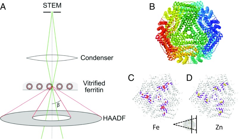
The experimental setting for recording electron scattering using ADF-STEM is depicted in Fig. 1A. Details specific to cryo-STEM appear in the recent literature (18). Briefly, a focused probe beam with a certain convergence angle scans across the specimen. The direct illumination beam strikes a bright-field detector on axis, while the flux scattered to higher angles is recorded on an annular detector. In cellular tomography a shallow convergence angle is advantageous to optimize depth of field, with some compromise in resolution. For detection of isolated metal atoms a tightly focused probe is preferred, since the strong scattering impulse will be diluted by the weaker scattering from lighter atoms. A tightly focused probe dictates use of a relatively large convergence angle. Spherical aberration limits the probe diameter of a conventional S/TEM (as used here, without aberration correction) operating at 200 kV to 0.25 nm, using a semiconvergence angle of 9.7 mrad. The inner cutoff of the dark-field detector must be set to collect larger angles.
Fig. 1.
Experimental setup. (A) Ray diagram of the cryo-STEM setup. The illuminating probe beam is focused on a spot that is rastered across the specimen. Electrons scattered to selected angles are collected incoherently on an ADF detector, with the inner cutoff angle (β) set by the diffraction camera length. Frozen-hydrated ferritin with a limited number of metal ions was imaged in cryogenic conditions. (B) X-ray structure of human heavy-chain ferritin viewed along the threefold axis, colored by chain (27). (C and D) Cutaway views of the structure in B, colored white (Inset). (C) Residues shown in purple are implicated in Fe transport from the channel via the ferroxidase to the mineral nucleation site (27); Fe ions are represented by red spheres for illustration. (D) Zn ions, shown as yellow spheres, bind tightly to the ferroxidase site. The structures in C and D are viewed from within the protein cavity, looking outward to the protein shell.
To assess the feasibility and limitations of isolated metal detection on a frozen-hydrated protein complex by STEM, we employ the metal-binding protein ferritin. Ferritin forms an approximately spherical hollow shell of 24 polypeptide chains with octagonal symmetry of four-, three-, and twofold axes (Fig. 1B). Here we use heavy-chain ferritin only. The heavy chain supports both iron uptake and oxidation. Iron uptake involves transport of single dissolved ions through the threefold axis channels (Fig. 1C). Ions entering as FeII are oxidized to FeIII at ferroxidase sites along the protein inner surface, partway along the α-helical bundles of the heavy chains. FeIII then deposits in mineral form at nucleation sites lying along the twofold axes.
Zn is a physiological regulator of Fe uptake. It binds strongly to the ferroxidase sites and inhibits further uptake of Fe. Extensive biochemistry shows that each ferroxidase site contains two nearby Zn-binding moieties, one of relatively high and one of relatively low affinity (26, 27) (Fig. 1D). Ferritin has been studied in depth by X-ray crystallography (27–29) as well as by single-particle EM (30). Iron deposits in ferritin have also been imaged by STEM, under both dried and native liquid-suspended conditions (31–35). Building on these studies, we set out to probe Zn and Fe binding to ferritin at very low stoichiometry.
Feasibility Estimate.
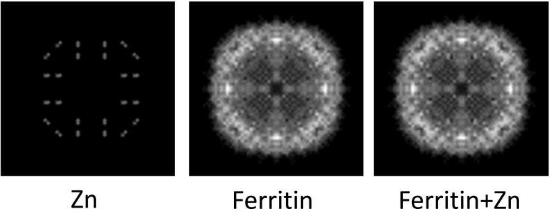
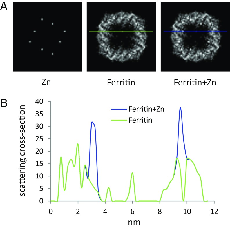
To evaluate the feasibility to see single metal atoms over protein density by Z contrast, we ran a simple “atom-counting” simulation. Using the atomic coordinates (PDB 2CEI) of human heavy-chain ferritin (27), we projected the number of atoms of each type, C, N, O, and S, in the protein onto a plane and made a histogram with bin width comparable to the STEM probe diameter of 0.25 nm. Each atom type was multiplied by its respective cross-section so that the sum represents the total scattering from the protein. Two Zn atoms were then added at the ferroxidase sites and their contribution was similarly calculated. According to this estimate, Zn peaks may be observed in single projections of the entire protein (Fig. S1); however, certain peaks in the C signal are stronger than those of the Zn. Therefore, detection of two Zn atoms against total protein background based only on peak strength will be marginal. On the other hand, 3D reconstruction effectively sections the protein structure into independent slices. Even with a relatively low resolution of 2 nm, the Zn atoms stand out as the strongest feature in the reconstruction (Fig. 2). We conclude that Zn atoms should be clearly visible as intensity peaks after 3D reconstruction.
Fig. S1.
ADF-STEM image simulation for projection through entire protein. Shown are projections of ferroxidase-site Zn atoms, ferritin protein, and ferritin+Zn, as marked. The Zn positions are still identifiable, but the Zn signal is weaker than some of the peak signals of the protein. Three-dimensional reconstruction reduces the effective thickness of protein to which the signal of isolated metal atoms should be compared, as in Fig. 2 of the main text.
Fig. 2.
ADF-STEM image simulation. (A) Simulation of ADF-STEM signal by atom-counting projection of the light elements (C, N, O, S) and Zn in the PDB file of human heavy-chain ferritin (2CEI). Each element contributes contrast weighted by the corresponding differential scattering cross-section integrated over angles greater than 13 mrad. The summed images represent a slice of 20-Å thickness. The Zn atoms as positioned in the PDB, ferritin alone, and ferritin+Zn atoms are shown in A, Left, A, Center, and A, Right, respectively. Images have been scaled and smoothed for high resolution display. (B) Line profiles across the ferritin and ferritin+Zn images as indicated in A show enhanced scattering of Zn atoms above that of the surrounding protein.
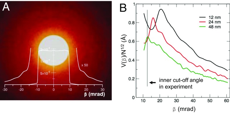
In addition to protein, the embedding-vitrified water contributes to the ADF-STEM signal. Intermediate range order and local inhomogeneity in the water density will contribute to fluctuations in the background signal and may limit the detectability of a single Zn atom. The essential concept is to avoid scattering angles where the signal from the vitrified water is maximum while using angles where the water signal is low due to destructive interference. For implementation, we performed multislice simulations to search for imaging conditions that would optimize visibility of the Zn (Fig. 3; details in Supporting Information). The nearest-neighbor distance between two adjacent oxygen atoms, 2.7 Å (36), gives rise to intensity modulations in diffraction space, with the first peak corresponding to a diffraction angle of 9.3 mrad. Convolved with the illumination semiconvergence angle of 9.7 mrad, we find a minimum in the scattering from water at a cutoff angle of about 13 mrad. At this inner collection angle the variation in the ADF signal from oxygen density fluctuations in vitreous ice is effectively minimized.
Fig. 3.
Optimization of ADF-STEM parameters for single-atom sensitivity. (A) Calculated diffraction pattern of vitreous ice with thickness 24 nm in the detection plane of the annular STEM detector. The diffraction pattern represents a particular frozen configuration of the vitreous ice. The central bright-field disk spans over the semiconvergence angle of 9.7 mrad. Beyond the bright-field disk, diffraction by vitreous ice produces intensity that results in a noise background in a real-space dark-field image. (B) Visibility of a single Zn atom in water as a function of the collection angle β. For an aqueous layer 12 nm thick, i.e., equal to the ferritin diameter, the maximum visibility is close to the illumination cone angle. For 24- and 48-nm-thick layers the sensitivity peaks at angles between 12 mrad and 16 mrad, i.e., the first diffraction intensity dip of the vitreous ice. The angular range of the visibility maximum corresponds well with the experiment setting of 12.7 mrad for the inner ADF collection angle.
Single-Particle Cryo-STEM of Ferritin–Metal Complexes.
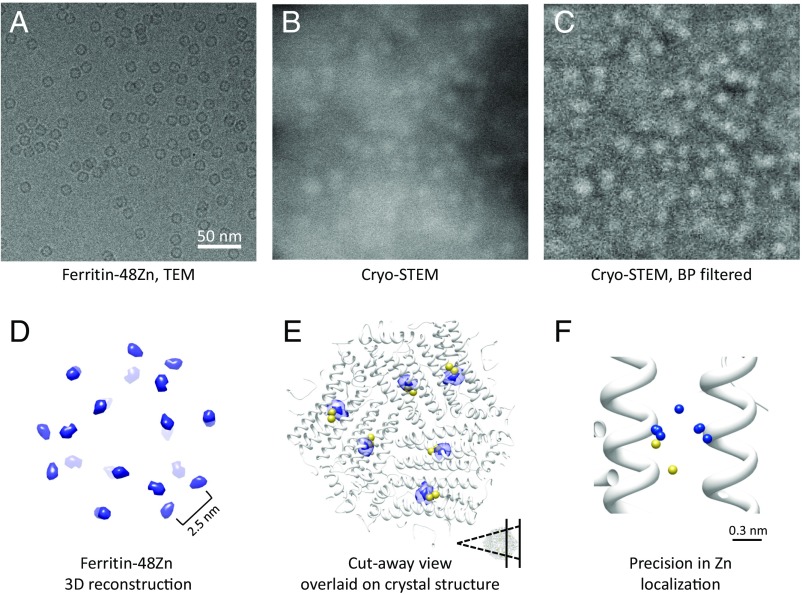
Bacterially expressed human heavy-chain ferritin was incubated in Zn solution at a stoichiometry of 48 Zn atoms per ferritin molecule. Given the 24-fold structure of ferritin we can expect that a stoichiometric ratio of 48:1 will fully fill the high-affinity ferroxidase sites and partly fill the lower-affinity sites (Fig. 1D). Hydrated ferritin samples were applied to TEM grids with thin carbon supports and imaged in the vitrified state by cryo-microscopy on a Tecnai TF20 electron microscope (FEI). Fig. 4A shows a field of the ferritin sample imaged using conventional defocus phase-contrast cryo-TEM. The typical ring shapes reflect the phase difference accumulated in the protein structure relative to the aqueous medium. In a similar specimen imaged by ADF cryo-STEM, ferritin–48Zn complexes are also easily recognized as bright objects of 12 nm diameter. The ring-like appearance in TEM is replaced, however, by a bright disk from which scattering is enhanced over that of the surrounding water (Fig. 4B). Variations in the ice thickness on the carbon support are apparent in the raw STEM image as variations in the background brightness. For the purpose of visualization, band-pass filtering flattens this background and permits a contrast stretch from the ferritin density (Fig. 4C). Based on the theoretical analysis of scattering above, we expect that some of the bright points are potentially isolated metal atoms. If so, they should localize to the ferritin symmetry-related positions. To that end we applied single-particle 3D reconstruction.
Fig. 4.
Single-particle cryo-STEM of ferritin–48Zn. (A) Ferritin complexes imaged using defocus phase-contrast cryo-TEM. (B) Ferritin–48Zn imaged using cryo-STEM. (C) The raw cryo-STEM image in B was band-pass filtered to remove the ice background, demonstrating the presence of detailed information in the image. Filtering was performed for the purpose of visualization only. (D) Three-dimensional reconstruction of ferritin–48Zn. (E) Cutaway view of the ferritin–48Zn map overlaid on the ferritin X-ray structure (Inset). The structures are viewed from within the protein cavity, looking outward to the protein shell and focusing on six of the Zn positions. Zn atoms from the X-ray structures appear in yellow. The reconstructed Zn density localizes to the ferroxidase sites anticipated from the X-ray structure. (F) Precision analysis estimated by reconstructing multiple maps from random halves of the dataset. Blue spheres indicate the peak positions of the different reconstructions at the same ferroxidase site. The peak positions are overlaid on the ferritin X-ray structure (white) with the Zn atom positions indicated by yellow spheres.
Ferritin particles were windowed from the cryo-STEM images and processed by standard single-particle methods. The ferritin–48Zn dataset comprised 647 particles in total. The initial model was generated from the low-pass–filtered protein density in the crystal structure with the Zn atoms removed manually (27). We observed convergence of the data to consistent 3D maps, using several different single-particle software packages and algorithms, including maximum likelihood and projection matching. Essentially identical results were obtained using different initial models, including ab initio models generated from the cryo-STEM images, indicating high signal-to-noise ratio (SNR) of the data. The reconstructed volume of the ferritin–48Zn is shown at high-isosurface threshold in Fig. 4D and additionally overlaid on the Zn-bound ferritin X-ray structure in Fig. 4E. The reconstructed density falls precisely on the ferroxidase sites anticipated from the X-ray structure, the density peak of the EM map being 3.8 Å away from the Zn in the X-ray structure. Given the possibility of packing or capillary forces affecting structure, we consider this an excellent agreement and conclude that these peaks in the reconstructed density are indeed the Zn atoms.
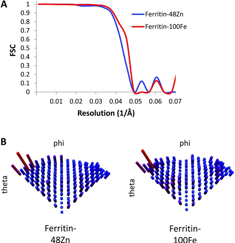
We next evaluated the localization precision for the Zn atoms in the 3D reconstructions. By analogy to superresolution light microscopy, precision can be defined as the statistical uncertainty in determining the peak of the intensity distribution. To this end, we calculated multiple 3D reconstructions from random halves of the dataset and compared the peak positions representing Zn atoms. Eight separate reconstructions yielded peak locations displaced by 2.5 Å mean absolute deviation (Fig. 4F and Table S1). Additionally, we calculated the classical resolution measure, which estimates the possibility to discriminate between nearby features. For the present data we obtain a resolution of 21 Å by the gold-standard Fourier shell correlation (FSC = 0.143) criterion (Fig. S2A). Indeed we can clearly resolve Zn atoms on neighboring ferroxidase sites at a distance of 25 Å (27). Similar to fluorescence superresolution localization microscopy, in looking for the metal locations the peak precision is a better measure of visibility than the width by which the spot is represented.
Table S1.
Peak positions representing Zn atoms calculated from random halves of the dataset (Fig. 4F)
| Zn peak | Peak position | |||
| x | y | z | Mean absolute deviation, Å | |
| 39.57 | 26.49 | 9.82 | 2.02 | |
| 39.69 | 26.30 | 9.93 | 2.25 | |
| 39.52 | 26.41 | 6.64 | 2.10 | |
| 39.54 | 29.65 | 6.80 | 2.57 | |
| 39.60 | 26.43 | 9.96 | 2.17 | |
| 39.46 | 29.67 | 6.56 | 2.71 | |
| 37.91 | 26.37 | 9.85 | 2.28 | |
| 36.32 | 29.62 | 6.52 | 3.73 | |
| Average | 38.95 | 27.62 | 8.26 | 2.48 |
Coordinates used to calculate the precision of Zn localization. The coordinates are of one (symmetry-related) Zn peak as it is positioned in the eight separate reconstructions from random halves of the dataset. Mean absolute deviation (boldface) is calculated as the average displacement of each peak from the global average position.
Fig. S2.
Resolution and angular distribution. (A) FSC curves for the ferritin–48Zn (blue) and ferritin–100Fe (red) reconstructions. (B) Angular distribution plots for assignment of the asymmetric unit.
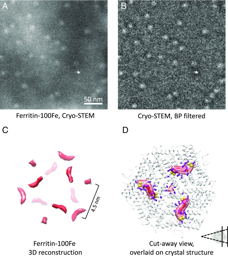
The case of Zn demonstrates detection of isolated metal atoms (or pairs) at symmetry-related locations in ferritin. Ferritin is primarily an iron storage protein, however. The Fe atoms accumulate within the spherical cavity and are not expected to adhere to a well-defined symmetry. At low stoichiometry, we expect to decorate sites of relatively high binding affinity, likely relating to the Fe uptake. Therefore, the experiments were repeated with a sample of protein incubated in Fe-containing solution, this time at a stoichiometry of 100 Fe ions per ferritin complex (Fig. 5 A and B). The 3D reconstruction from a dataset of 1,484 particles shows the Fe density stretched in an arc between neighboring ferroxidase sites. The maximum is found at the twofold axis, corresponding to the mineral nucleation site (Fig. 5 C and D). Although its functional activity has been contested (37), our observations provide direct evidence for the role of this site in nucleation. Since the reconstruction is generated from an ensemble of protein structures, we interpret the continuous density as a map of the probability to find the metal ion at a particular location. An additional disconnected density is found at the channel on the threefold axis, but not at the fourfold channel.
Fig. 5.
Single-particle cryo-STEM of ferritin–100Fe. (A) Ferritin–100Fe imaged using cryo-STEM. (B) For visualization, the raw cryo-STEM image in A was band-pass filtered to remove the ice background. (C) Three-dimensional reconstruction of ferritin–100Fe. (D) Cutaway view of the ferritin–100Fe map overlaid on the ferritin X-ray structure. The structures are viewed from within the protein cavity, focusing on three of the Fe positions (Inset). The ferritin–100Fe map is shown with two isosurface thresholds. The higher threshold (opaque red) indicates the peak position at the mineral nucleation site. At a lower contour threshold (transparent red) the Fe density corresponds to the anticipated path of the Fe atoms, including the entry site on the threefold axis. Residues from the X-ray structure involved in the Fe path are colored purple. Yellow spheres indicate the position of the Zn atoms at the ferroxidase sites in the X-ray structure for comparison with Fig. 4E.
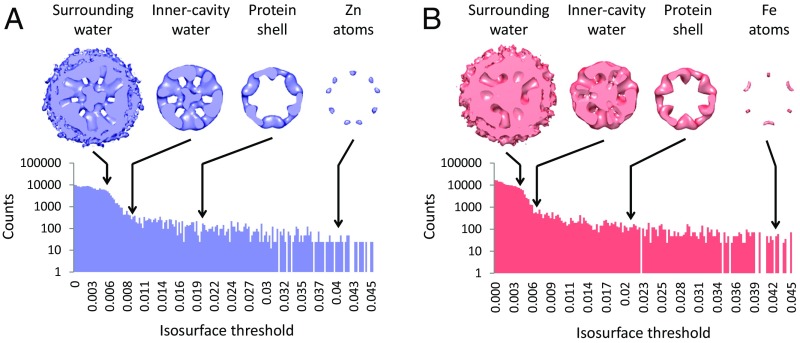
In accordance with the feasibility estimates, we have identified the peak intensities in the reconstructions with the locations of metal ions. ADF-STEM provides a quantitative measurement of the total scattering, so we expect to see the protein at a lower threshold and, below that, the water. Examining the intensity histogram for the two reconstructions, we can identify these distinct ranges (Fig. 6). At intensity level 0 the surrounding water volume is filled (this is consistent with the normalization protocol in RELION, which sets the surrounding background level to zero). The surrounding water persists up to a threshold of 0.008, beyond which the protein stands out. Interestingly, water in the protein cavity persists up to a threshold of 0.017 (Zn) or 0.02 (Fe). From this value upward we observe primarily protein. Indeed the two independent reconstructions appear almost identical. At the highest thresholds, above ∼0.035, the density no longer corresponds to the protein structure, and the Zn and Fe reconstructions diverge. At these thresholds we identify the metal atoms.
Fig. 6.
(A and B) Analysis of water and protein signals in the cryo-STEM maps. Three-dimensional reconstructions of the ferritin–48Zn (blue) (A) and ferritin–100Fe (red) (B) are shown. Contour threshold levels of the reconstructions are indicated on the corresponding intensity histograms. At the lower level the surrounding water volume is filled, while water within the cavity persists up to a significantly higher level. The protein and metal persist to yet higher contour levels. Finally, at the highest level the density no longer corresponds to the protein structure and only metal is observed (as in Figs. 4D and 5C). Except for the metal ions density at the highest contour levels, the protein structures are very similar.
Discussion
The prospect for precise detection of metal atoms in frozen-hydrated protein complexes has been realized using cryo-STEM. Single-atom studies are blossoming in the materials sciences. The typical specimens are much more resistant to radiation damage, so it was not obvious that delicate cryogenic specimens would survive the required imaging conditions. We have found a configuration of the STEM parameters that provides a suitably high SNR under cryogenic conditions. STEM signals can in principle be interpreted quantitatively, and indeed, even after 3D reconstruction the image intensities associated with water, protein, or metal atoms are effectively separated.
It is instructive to compare the image formation by STEM to that by TEM using conventional defocus phase contrast. For the latter, the contrast transfer function suppresses low spatial frequencies; this has the effect of a high-pass filter, similar to background subtraction. As an interferometric method, phase-contrast TEM offers high sensitivity for weak-phase objects such as protein embedded in vitreous ice. STEM offers less contrast from hydrated protein at high resolution (13, 38). Indeed the ferritin features appear at low resolution. On the other hand, the high-angle scattering signal that is collected in ADF-STEM hardly contributes to a phase-contrast image. Specifically, the high-angle scattering beyond ∼10 mrad is not effectively focused by the TEM objective due to defocus and spherical aberration. STEM intensities can be interpreted more quantitatively than defocus phase contrast, and the intensities associated with water, protein, or metal atoms are effectively separated. Between resolution of protein structure and sensitivity to isolated metals, the two methods offer complementary information. In principle, a complete picture should benefit from the combination of both modalities.
The striking difference between Zn and Fe localizations reflects the different local distribution of these metals in ferritin. In particular, the iron path is revealed along the protein inner shell between the ferroxidase and the mineral nucleation sites. The approach is now established for application to other metal-binding macromolecules such as enzymes, ion channels, and nucleic acids. Faithful identification of heavy atoms will also be essential in detection of metal tags as protein labels for future cryo-microscopy and tomography in the cellular context (19, 20, 39, 40).
Materials and Methods
Contrast Simulation by Atom Counting.
To estimate the feasibility to detect isolated metal atoms, the PDB file 2CEI (27) was manipulated to tabulate coordinates for C, N, O, S, and Zn atoms independently. Zn atoms not corresponding to the ferroxidase sites were removed manually (the crystal structure was obtained at a higher Zn concentration). To project along the z axis, a 2D histogram was prepared for each element individually with a bin size of 0.25 nm corresponding to the microscope probe diameter. The number of atoms in each bin was multiplied by the relevant scattering cross-section per element, integrated from a prespecified cutoff angle of 13 mrad. The resulting arrays were then summed as total protein, with or without Zn, for analysis as 2D images (Fig. S1). To limit the projections to a reconstructed slice, the lists were first sorted according to the Z coordinate and then truncated to coordinates in a range of 2 nm from the first appearance of a Zn atom. Projections prepared from this limited slice appear in Fig. 2A. Image processing was performed with a combination of custom Python scripts and ImageJ (41).
Protein Purification and Sample Preparation.
Human heavy-chain ferritin was expressed as a recombinant protein in Escherichia coli (BL21) by using the constitutive expression vector pET12a (Invitrogen). Bacteria were incubated at 37 °C for 15–18 h and harvested by centrifugation, and the pellet was resuspended in buffer (50 mM Tris⋅HCl, pH 7.5, 1 mM EDTA, and 300 mM NaCl containing a protease inhibitor mixture). Cells were lysed by sonication on ice and treated with DNase I enzyme (Sigma-Aldrich) (0.1 mg/mL final concentration with 3 mM MgCl2, at 37 °C for 60 min). Thermally labile proteins were removed by two consecutive thermal steps (8 min each incubation) at 55 °C and 75 °C, respectively, followed by centrifugation at 18,000 × g for 20 min. Remaining protein was loaded onto a MonoQ HP column (GE Healthcare) equilibrated with 30 mM Tris⋅HCl, pH 7.2. Purification was performed on an Akta Purifier FPLC system (GE Healthcare). Ferritin was eluted using 30% NaCl and dialyzed overnight in 30 mM Tris⋅HCl, pH 7.5. Buffer was exchanged using Amicon concentrators for 50 mM Hepes-NaOH, 0.2 M NaCl, pH 7.2. Purified protein was stored in this buffer at −80 °C. For metal loading, stock protein (2.9 mg/mL) was diluted to 0.25 mg/mL and mixed with a 48-fold molar excess of Zn(II)SO4 or a 100-fold excess of Fe(II)SO4 solution in 50 mM Hepes-NaOH, 0.2 M NaCl, pH 7.2.
A total of 3.5 μL of purified ferritin at 0.13 mg/mL concentration was applied to glow-discharged Quantifoil holey carbon gold grids (R2/1, 200 mesh) that had been coated with a thin layer of carbon. Samples were blotted for 3.5 s and plunge frozen in liquid ethane cooled by liquid nitrogen, using a Leica EM-GP plunger at 95% humidity.
Electron Microscopy.
Grids were imaged at liquid nitrogen temperature on an FEI Tecnai TF20 Twin STEM/TEM electron microscope with a side-entry Gatan 626 cryo-holder. In both STEM and TEM modes the microscope was operated at 200 kV acceleration voltage, extraction voltage = 3,850 V and gun lens = 6. STEM images were collected with the following microscope settings: condenser aperture = 70 μm, spot size = 6, camera length = 520 mm, nominal magnification = 450,000×, dwell time = 0.79 μs, frame size = 2,048 × 2,048 pixels, calibrated pixel size = 1.65 Å, probe diameter = 2.5 Å. The camera length sets the ADF inner cutoff angle to 12.7 mrad. Due to hardware geometry, the bright-field detector then collects only a very small fraction of the projected illumination cone.
The dose per probe sample was estimated to be 127 e−/Å2 by projecting the beam onto the US4000 camera (Gatan, Inc.) and converting integrated counts to electrons with a factor of 10.4 (provided by the manufacturer). The total dose seen by the sample is larger due to oversampling but is spread over sequential exposures. ADF images were collected with a Fischione Model 3000 high-angle annular DF detector located above the fluorescent viewing screen. Focus was manually adjusted before each image on the carbon film immediately next to the imaging area. TEM images were taken using a Gatan US4000 camera with a defocus of about 3 µm.
Image Processing.
The ferritin–48Zn comprised 647 particles from 15 images and the ferritin–100Fe dataset comprised 1,484 particles from 58 images. All particles were manually picked using EMAN2 e2boxer (42), extracted into 160 × 160 pixel boxes, binned by a factor of 2, and normalized using a round mask of 25 pixels to define background in RELION (43). No band-pass filtering was done before the reconstruction procedure. To avoid the potential reference bias we have tested different initial models for 3D refinement as follows: An initial model was prepared from the human ferritin heavy-chain crystal structure (27) from which all heavy atoms were removed. The protein PDB coordinates were converted to structure factors and low-pass filtered to 4 nm. Other initial models were obtained with a completely smooth shell model or by random assignment of angles using Prime (44), followed by octagonal symmetrization using Bsoft (45). These starting models gave similar results.
Initial models were 3D refined in RELION, using the default settings and applying octagonal symmetry. Very similar results were obtained using an iterative projection matching procedure implemented in SPIDER (46). The AP SH module was used for alignment and BP 32F for back projection. Figures of the 3D maps were prepared using Chimera (47).
Precision of Zn localization (Fig. 4F and Table S1) was estimated by calculating nine maps from random halves of the dataset, using RELION. Maps were overlaid in Chimera (47) and the x, y, z coordinates of one of the symmetry-related peaks were registered for each of the nine maps. Precision was then calculated as the mean absolute deviation of the peak coordinated in 3D.
Multislice Simulations for Determination of Optimum Detection Angles
Here, a dynamical diffraction simulation based on an atomistic model of amorphous water was used to assess the detection angles for an ADF-STEM signal that optimize the separation of the signal of a single Zn atom from the background signal. Multislice simulations were performed using the Dr Probe software suite (48). Atomic coordinates for amorphous water were modeled using a molecular dynamics simulation following ref. 20. Calculations considered elastic scattering of electrons, using the frozen lattice approximation for high-angle scattering. Inelastic scattering was neglected, as elastic scattering dominates at high angles. Projected electrostatic potentials of supercell slices for the multislice iteration were calculated using the parameterization of Weickenmeier and Kohl (49) with random atom displacements representing frozen-state variants of thermal atom vibration. For each simulation of a diffraction pattern in the detection plane about 1,000 atomistic configurations were averaged. The electron probe represented the experimental setup using a Tecnai F20 with Twin lens, i.e., for an electron energy of 200 kV and a spherical aberration coefficient of 2.0 mm. The probe semiconvergence angle was 9.7 mrad.
Since vitrified water has nearest-neighbor and intermediate range order, the intensity recorded in the detection plane of a STEM is not a monotonic function of scattering angle. Fig. 3A (main text) shows an example of the diffraction signal from a 24-nm-thick slab of vitrified water, as it would be observed in a STEM with a 200-keV probe with a 9.7-mrad semiconvergence angle at Scherzer conditions. The bright central disk represents the bright-field intensity, beyond which the dark field extends. Fig. 3A also displays (on a logarithmic scale) the radial profile of the scattered intensity as a function also of the scattering angle. Between 10 mrad and 20 mrad the scattered intensity from water drops by more than an order of magnitude, followed by a less steep decrease in scattered intensity at higher angles.
The scattered intensity between 10 mrad and 20 mrad corresponds to the first sharp diffraction peak of water (50). This means that the strong scattering signal associated with the first sharp diffraction peak in water should be avoided. On the one hand, this restricts the use of lower scattering angles just outside the semiconvergence angle, 9.7 mrad in our experiment. On the other hand, the use of higher angles becomes inefficient when the water thickness becomes so large that multiple scattering increases the background at higher angles.
Fig. 3B further details the visibility of a single Zn atom against the background of vitrified ice as a function of the scattering angle β. We can define the visibility V(β) of the single atom at a certain β as the ratio between the diffracted wave power I of the single atom and the SD of the power of the noise at β. The SD of the noise power can be approximated by the geometric sum of the variances of the single-atom signal var(I(β)) and of the vitrified-ice background var(IH20(β)). Here we neglect detection noise. V(β) then becomes
Assuming Poisson noise statistics for I(β) and IH20(β) and defining the signal-to-background ratio SBR(β) = I(β)/IH20(β), one can rewrite V(β) as
where the latter approximation is fulfilled in the scenario of a poor SBR. For a single atom the recorded wave power I(β) is equivalent to the product of the number density of incident primary electrons N times the differential scattering cross-section dσ/dΩ(β) = |f(β)|2 when f(β) is the atomic scattering factor for an elastic scattering event. I(β) for vitrified ice was calculated from the averaged diffraction patterns that were obtained with the multislice approach. Angular modulations in I(β), which are a consequence of coordination order in the vitrified ice, and which manifest in the typical speckled image contrast of ice, were therefore taken into account.
The visibility V(β) can then further be simplified to
Fig. 3B shows a descriptive interpretation of the visibility as an effective scattering factor for the signal of a single atom in the presence of a background signal from water.
The simulation confirms the existence of a maximum for the visibility of a single Zn atom as a function of the scattering angle at a lower detection angle than is usually recommended for high-angle ADF detection. For a thin slab of vitrified ice the maximum visibility is located at 20 mrad but flattens and shifts considerably to lower angles with increasing water thickness, owing to the increase in multiple scattering. At a thickness corresponding to the size of a ferritin molecule the maximum visibility is given at 16 mrad. A practically reasonable choice for the lower cutoff of the ADF detector in that case is the point of inflection to the maximum in visibility at 13 mrad.
Acknowledgments
We are grateful to Bart De Strooper for support during the project, to Jose Maria Carazo and Carlos Oscar Sanchez for discussions on data verification, and to Akif Tezcan for discussion on ferritin structures. This work was funded in part by a grant from the Israel Science Foundation (Grant 1285/14). Support from the Henry Chanoch Krenter Institute for Biomedical Imaging and Genomics, the Gerhardt M. J. Schmidt Minerva Center for Supramolecular Architecture, and the Irving and Cherna Moskowitz Center for Nano and Bionano Imaging is also gratefully acknowledged. The laboratory of M.E. has benefited from the historical generosity of the Harold Perlman family.
Footnotes
The authors declare no conflict of interest.
This article is a PNAS Direct Submission.
Data deposition: The cryo-STEM maps of the ferritin-48Zn and ferritin-100Fe reconstructions have been deposited in the EM Data Bank, www.emdatabank.org (accession nos. EMD-3848 and EMD-3849, respectively).
This article contains supporting information online at www.pnas.org/lookup/suppl/doi:10.1073/pnas.1708609114/-/DCSupplemental.
References
- 1.Thomson AJ, Gray HB. Bio-inorganic chemistry. Curr Opin Chem Biol. 1998;2:155–158. doi: 10.1016/s1367-5931(98)80056-2. [DOI] [PubMed] [Google Scholar]
- 2.Dudev T, Lim C. Principles governing Mg, Ca, and Zn binding and selectivity in proteins. Chem Rev. 2003;103:773–788. doi: 10.1021/cr020467n. [DOI] [PubMed] [Google Scholar]
- 3.Nannenga BL, Gonen T. MicroED opens a new era for biological structure determination. Curr Opin Struct Biol. 2016;40:128–135. doi: 10.1016/j.sbi.2016.09.007. [DOI] [PMC free article] [PubMed] [Google Scholar]
- 4.Kühlbrandt W. Cryo-EM enters a new era. Elife. 2014;3:e03678. doi: 10.7554/eLife.03678. [DOI] [PMC free article] [PubMed] [Google Scholar]
- 5.Bai XC, McMullan G, Scheres SHW. How cryo-EM is revolutionizing structural biology. Trends Biochem Sci. 2015;40:49–57. doi: 10.1016/j.tibs.2014.10.005. [DOI] [PubMed] [Google Scholar]
- 6.Cheng Y. Single-particle cryo-EM at crystallographic resolution. Cell. 2015;161:450–457. doi: 10.1016/j.cell.2015.03.049. [DOI] [PMC free article] [PubMed] [Google Scholar]
- 7.Crewe AV, Wall J, Langmore J. Visibility of single atoms. Science. 1970;168:1338–1340. doi: 10.1126/science.168.3937.1338. [DOI] [PubMed] [Google Scholar]
- 8.Colliex C, et al. Capturing the signature of single atoms with the tiny probe of a STEM. Ultramicroscopy. 2012;123:80–89. doi: 10.1016/j.ultramic.2012.04.003. [DOI] [PubMed] [Google Scholar]
- 9.Hovden R, Muller DA. Efficient elastic imaging of single atoms on ultrathin supports in a scanning transmission electron microscope. Ultramicroscopy. 2012;123:59–65. doi: 10.1016/j.ultramic.2012.04.014. [DOI] [PubMed] [Google Scholar]
- 10.Wall JS, Hainfeld JF. Mass mapping with the scanning transmission electron microscope. Annu Rev Biophys Biophys Chem. 1986;15:355–376. doi: 10.1146/annurev.bb.15.060186.002035. [DOI] [PubMed] [Google Scholar]
- 11.Engel A. Scanning transmission electron microscopy: Biological applications. In: Hawkes PW, editor. Advances in Imaging and Electron Physics. Vol 159. Elsevier; New York: 2009. pp. 357–386. [Google Scholar]
- 12.Luo RZ-T, Beniac DR, Fernandes A, Yip CC, Ottensmeyer FP. Quaternary structure of the insulin-insulin receptor complex. Science. 1999;285:1077–1080. doi: 10.1126/science.285.5430.1077. [DOI] [PubMed] [Google Scholar]
- 13.Trachtenberg S, Leonard KR, Tichelaar W. Radial mass density functions of vitrified helical specimens determined by scanning transmission electron microscopy: Their potential use as substitutes for equatorial data. Ultramicroscopy. 1992;45:307–321. doi: 10.1016/0304-3991(92)90142-7. [DOI] [PubMed] [Google Scholar]
- 14.Aoyama K, Takagi T, Hirase A, Miyazawa A. STEM tomography for thick biological specimens. Ultramicroscopy. 2008;109:70–80. doi: 10.1016/j.ultramic.2008.08.005. [DOI] [PubMed] [Google Scholar]
- 15.Hohmann-Marriott MF, et al. Nanoscale 3D cellular imaging by axial scanning transmission electron tomography. Nat Methods. 2009;6:729–731. doi: 10.1038/nmeth.1367. [DOI] [PMC free article] [PubMed] [Google Scholar]
- 16.Yakushevska AE, et al. STEM tomography in cell biology. J Struct Biol. 2007;159:381–391. doi: 10.1016/j.jsb.2007.04.006. [DOI] [PubMed] [Google Scholar]
- 17.Klein T, Buhr E, Georg Frase C. TSEM: A review of scanning electron microscopy in transmission mode and its applications. In: Hawkes PW, editor. Advances in Imaging and Electron Physics. Vol. 171. Elsevier; New York: 2012. pp. 297–356. [Google Scholar]
- 18.Elbaum M, Wolf SG, Houben L. Cryo-scanning transmission electron tomography of biological cells. MRS Bull. 2016;41:542–548. doi: 10.1038/nmeth.2842. [DOI] [PubMed] [Google Scholar]
- 19.Wolf SG, Houben L, Elbaum M. Cryo-scanning transmission electron tomography of vitrified cells. Nat Methods. 2014;11:423–428. doi: 10.1038/nmeth.2842. [DOI] [PubMed] [Google Scholar]
- 20.Kirchenbuechler D, et al. Cryo-STEM tomography of intact vitrified fibroblasts. AIMS Biophys. 2015;2:259–273. [Google Scholar]
- 21.Rez P, Larsen T, Elbaum M. Exploring the theoretical basis and limitations of cryo-STEM tomography for thick biological specimens. J Struct Biol. 2016;196:466–478. doi: 10.1016/j.jsb.2016.09.014. [DOI] [PubMed] [Google Scholar]
- 22.Kellenberger E, et al. Z-contrast in biology. A comparison with other imaging modes. Ann N Y Acad Sci. 1986;483:202–228. doi: 10.1111/j.1749-6632.1986.tb34522.x. [DOI] [PubMed] [Google Scholar]
- 23.Rez D, Rez P, Grant I. Dirac–Fock calculations of X-ray scattering factors and contributions to the mean inner potential for electron scattering. Acta Crystallogr A. 1994;50:481–497. [Google Scholar]
- 24.Sousa AA, Hohmann-Marriott M, Aronova MA, Zhang G, Leapman RD. Determination of quantitative distributions of heavy-metal stain in biological specimens by annular dark-field STEM. J Struct Biol. 2008;162:14–28. doi: 10.1016/j.jsb.2008.01.007. [DOI] [PMC free article] [PubMed] [Google Scholar]
- 25.Wolf SG, Rez P, Elbaum M. Phosphorus detection in vitrified bacteria by cryo-STEM annular dark-field analysis. J Microsc. 2015;260:227–233. doi: 10.1111/jmi.12289. [DOI] [PubMed] [Google Scholar]
- 26.Bou-Abdallah F, et al. Ferrous ion binding to recombinant human H-chain ferritin. An isothermal titration calorimetry study. Biochemistry. 2002;41:11184–11191. doi: 10.1021/bi020215g. [DOI] [PubMed] [Google Scholar]
- 27.Toussaint L, Bertrand L, Hue L, Crichton RR, Declercq J-P. High-resolution X-ray structures of human apoferritin H-chain mutants correlated with their activity and metal-binding sites. J Mol Biol. 2007;365:440–452. doi: 10.1016/j.jmb.2006.10.010. [DOI] [PubMed] [Google Scholar]
- 28.Lawson DM, et al. Solving the structure of human H ferritin by genetically engineering intermolecular crystal contacts. Nature. 1991;349:541–544. doi: 10.1038/349541a0. [DOI] [PubMed] [Google Scholar]
- 29.Pozzi C, et al. Iron binding to human heavy-chain ferritin. Acta Crystallogr D Biol Crystallogr. 2015;71:1909–1920. doi: 10.1107/S1399004715013073. [DOI] [PubMed] [Google Scholar]
- 30.Russo CJ, Passmore LA. Electron microscopy: Ultrastable gold substrates for electron cryomicroscopy. Science. 2014;346:1377–1380. doi: 10.1126/science.1259530. [DOI] [PMC free article] [PubMed] [Google Scholar]
- 31.Ohtsuki M, Isaacson MS, Crewe AV. Dark field imaging of biological macromolecules with the scanning transmission electron microscope. Proc Natl Acad Sci USA. 1979;76:1228–1232. doi: 10.1073/pnas.76.3.1228. [DOI] [PMC free article] [PubMed] [Google Scholar]
- 32.Pan Y-H, et al. 3D morphology of the human hepatic ferritin mineral core: New evidence for a subunit structure revealed by single particle analysis of HAADF-STEM images. J Struct Biol. 2009;166:22–31. doi: 10.1016/j.jsb.2008.12.001. [DOI] [PMC free article] [PubMed] [Google Scholar]
- 33.Evans JE, et al. Visualizing macromolecular complexes with in situ liquid scanning transmission electron microscopy. Micron. 2012;43:1085–1090. doi: 10.1016/j.micron.2012.01.018. [DOI] [PMC free article] [PubMed] [Google Scholar]
- 34.Wang C, Qiao Q, Shokuhfar T, Klie RF. High-resolution electron microscopy and spectroscopy of ferritin in biocompatible graphene liquid cells and graphene sandwiches. Adv Mater. 2014;26:3410–3414. doi: 10.1002/adma.201306069. [DOI] [PubMed] [Google Scholar]
- 35.Jian N, Dowle M, Horniblow RD, Tselepis C, Palmer RE. Morphology of the ferritin iron core by aberration corrected scanning transmission electron microscopy. Nanotechnology. 2016;27:46LT02. doi: 10.1088/0957-4484/27/46/46LT02. [DOI] [PubMed] [Google Scholar]
- 36.McMullan G, Vinothkumar KR, Henderson R. Thon rings from amorphous ice and implications of beam-induced Brownian motion in single particle electron cryo-microscopy. Ultramicroscopy. 2015;158:26–32. doi: 10.1016/j.ultramic.2015.05.017. [DOI] [PMC free article] [PubMed] [Google Scholar]
- 37.Bou-Abdallah F, Biasiotto G, Arosio P, Chasteen ND. The putative “nucleation site” in human H-chain ferritin is not required for mineralization of the iron core. Biochemistry. 2004;43:4332–4337. doi: 10.1021/bi0498813. [DOI] [PubMed] [Google Scholar]
- 38.Rez P. Comparison of phase contrast transmission electron microscopy with optimized scanning transmission annular dark field imaging for protein imaging. Ultramicroscopy. 2003;96:117–124. doi: 10.1016/S0304-3991(02)00436-9. [DOI] [PubMed] [Google Scholar]
- 39.Mercogliano CP, DeRosier DJ. Concatenated metallothionein as a clonable gold label for electron microscopy. J Struct Biol. 2007;160:70–82. doi: 10.1016/j.jsb.2007.06.010. [DOI] [PMC free article] [PubMed] [Google Scholar]
- 40.Diestra E, Fontana J, Guichard P, Marco S, Risco C. Visualization of proteins in intact cells with a clonable tag for electron microscopy. J Struct Biol. 2009;165:157–168. doi: 10.1016/j.jsb.2008.11.009. [DOI] [PubMed] [Google Scholar]
- 41.Schneider CA, Rasband WS, Eliceiri KW. NIH image to ImageJ: 25 years of image analysis. Nat Methods. 2012;9:671–675. doi: 10.1038/nmeth.2089. [DOI] [PMC free article] [PubMed] [Google Scholar]
- 42.Tang G, et al. EMAN2: An extensible image processing suite for electron microscopy. J Struct Biol. 2007;157:38–46. doi: 10.1016/j.jsb.2006.05.009. [DOI] [PubMed] [Google Scholar]
- 43.Scheres SHW. RELION: Implementation of a Bayesian approach to cryo-EM structure determination. J Struct Biol. 2012;180:519–530. doi: 10.1016/j.jsb.2012.09.006. [DOI] [PMC free article] [PubMed] [Google Scholar]
- 44.Elmlund H, Elmlund D, Bengio S. PRIME: Probabilistic initial 3D model generation for single-particle cryo-electron microscopy. Structure. 2013;21:1299–1306. doi: 10.1016/j.str.2013.07.002. [DOI] [PubMed] [Google Scholar]
- 45.Heymann JB, Belnap DM. Bsoft: Image processing and molecular modeling for electron microscopy. J Struct Biol. 2007;157:3–18. doi: 10.1016/j.jsb.2006.06.006. [DOI] [PubMed] [Google Scholar]
- 46.Frank J, et al. SPIDER and WEB: Processing and visualization of images in 3D electron microscopy and related fields. J Struct Biol. 1996;116:190–199. doi: 10.1006/jsbi.1996.0030. [DOI] [PubMed] [Google Scholar]
- 47.Pettersen EF, et al. UCSF Chimera–A visualization system for exploratory research and analysis. J Comput Chem. 2004;25:1605–1612. doi: 10.1002/jcc.20084. [DOI] [PubMed] [Google Scholar]
- 48.Barthel J. 2012. Time-efficient frozen phonon multislice calculations for image simulations in high-resolution STEM. J Microsc (abstr)
- 49.Weickenmeier A, Kohl H. Computation of the atomic inner-shell excitation cross-sections for fast electrons in crystals. Phil Mag. 1989;60:467–479. [Google Scholar]
- 50.Elliott SR. Interpretation of the principal diffraction peak of liquid and amorphous water. J Chem Phys. 1995;103:2758–2761. [Google Scholar]


