Abstract
Objective
Deep brain stimulation (DBS) of the centromedian thalamic nucleus (CM) can be an alternative treatment option for intractable epilepsy patients. Since CM may be involved in widespread cortico-subcortical networks, identification of the cortical sub-networks specific to the target stimuli may provide further understanding on the underlying mechanisms of CM DBS. Several brain structures have distinguishing brain connections that may be related to the pivotal propagation and subsequent clinical effect of DBS.
Methods
To explore core structures and their connections relevant to CM DBS, we applied electroencephalogram (EEG) and diffusion tensor imaging (DTI) to 10 medically intractable patients – three generalized epilepsy (GE) and seven multifocal epilepsy (MFE) patients unsuitable for resective surgery. Spatiotemporal activation pattern was mapped from scalp EEG by delivering low-frequency stimuli (5 Hz). Structural connections between the CM and the cortical activation spots were assessed using DTI.
Results
We confirmed an average 72% seizure reduction after CM DBS and its clinical efficiency remained consistent during the observation period (mean 21 months). EEG data revealed sequential source propagation from the anterior cingulate, followed by the frontotemporal regions bilaterally. In addition, maximal activation was found in the left cingulate gyrus and the right medial frontal cortex during the right and left CM stimulation, respectively. From DTI data, we confirmed concrete structural connections between CM and those maximal activation spots identified from EEG data.
Conclusion
These results suggest that the anterior cingulate can be a core cortical structure for the bilateral propagation of CM stimulation. Our DTI findings also indicate that the propagation of CM stimulation may rely upon integrity of structural connections between CM and these key cortical regions. Structures and their connections found in this study may be relevant in the interpretation of the clinical outcomes of CM DBS.
Keywords: deep brain stimulation, intractable epilepsy, centromedian thalamic nucleus, structural connectivity, cortical recruiting response, anterior cingulate
Introduction
In spite of the development of new antiepileptic drugs to control seizures, 30% of epilepsy patients experience inadequate control of their seizures.1 Resective surgery is a standard treatment for patients with pharmacoresistant epilepsy. In medial temporal lobe epilepsy patients, an anterior temporal lobectomy can lead to excellent long-term outcomes.2 However, for intractable epilepsy patients who are not candidates for surgical resection, deep brain stimulation (DBS) can be an alternative treatment.3 The anterior thalamic nucleus (ATN) is a well-known DBS target for controlling intractable epilepsy. Recently, some studies proposed the centromedian thalamic nucleus (CM) as a new target. CM DBS is more effective for patients with generalized epilepsy (GE) than for those with focal epilepsy (FE).3–6 Unlike the ATN, the CM has widespread connections into the striatum and diffuse frontal areas that provide a sound basis for CM DBS as a useful treatment option for GE and frontal lobe epilepsy.3,7
Low-frequency stimulation of the thalamic nuclei creates cortical recruiting responses (CRs).8,9 Some previous studies reported that the low-frequency stimulation of the CM causes CRs in scalp electroencephalogram (EEG).4,8 Various low-frequency stimuli have been used to induce CR; however, the optimal frequency of stimulation has not been identified yet.4,8,9 We chose 5 Hz stimulation for inducing CR, because 5 Hz-rhythmic slow was clearly distinguishable from normal alpha or abnormal slow wave by visual inspection. CR analysis is a tool for determining cortical activation patterns, mechanisms, and predictive factors with respect to DBS stimulation.8,10 In addition, CR has proved effective in predicting clinical prognosis and optimal DBS electrode position.10–12 CM low-frequency stimulation can induce a characteristic CR that suggests the wide connection between CM and diffuse cortical areas.3,13
We combined a multimodal neuroimaging and electro-physiological approach to conceptualize the mechanism for the antiseizure effects of CM DBS. To investigate the cortical activation pattern during the administration of CM DBS, we initially focused on a CR propagation pattern using a source analysis technique. Then, we performed diffusion tensor imaging (DTI) tractography to confirm and visualize the microstructural connections between the CM and the associated cortical areas.
Methods
Subjects and study design
In this study, we enrolled 10 medically intractable epilepsy patients (four males and six females, mean age 30.6±8.8 years, mean seizure duration 19.7±9.7 years) using the following criteria: frequent (more than 2 per month) and disabling seizures uncontrolled by multiple medications, not candidates for resective surgical treatment as determined using video-EEG monitoring (eg, multifocal ictal onset zone).
All patients were evaluated with a neurologic examination, clinical history, and brain imaging. Each patient underwent conventional magnetic resonance imaging (MRI) and DTI. Five patients showed structural abnormalities (four schizencephaly and one heterotopia), and the other five patients (two women) had normal brain MRI findings: three of them had Lennox–Gastaut syndrome (GE group) and the other two had FE (Table 1). This study was approved by the local ethics committee of Seoul St Mary’s Hospital, Seoul, Republic of Korea. Informed written consent was obtained from all patients who had the capacity to provide consent. For four participants (three subjects with LGS, P1~3 and one with schizencephaly, P10; Table 1) who were intellectually disabled, written informed consent was provided by the nearest family members or relatives who had legal guardianship. For a patient who was 16 years old (P5; Table 1), we obtained a written informed consent from the parents.
Table 1.
Demographics and clinical information of participants
| Patient ID number | Diagnosis | Age (y) | Sex | Age at seizure onset (y) | Duration of epilepsy (y) | Seizure classification | Brain MRI finding | Site of CM DBS electrodes with optimal CR
|
Postoperative follow-up (months) | Mean seizure reduction (%) | |
|---|---|---|---|---|---|---|---|---|---|---|---|
| R | L | ||||||||||
| P1 | LGS | 35 | M | 3 | 32 | Tonic, myoclonic, absence | Nonspecific | 2–/3+ | 2–/3+ | 18 | 26.8 |
| P2 | LGS | 23 | M | 1 | 22 | Tonic, absence | Nonspecific | 2–/3+ | 2–/3+ | 24 | 52 |
| P3 | LGS | 21 | F | 1 | 20 | Tonic, absence, GTCs | Nonspecific | 0–/3+ | 1–/3+ | 27 | 78.5 |
| P4 | Multifocal (B F-PLE) | 26 | M | 23 | 3 | Focal to bilateral convulsive | Nonspecific | 2–/3+ | 1–/2+ | 6 | 99.2 |
| P5 | Multifocal (B F-TLE) | 16 | F | 1 | 15 | Focal to bilateral convulsive | Nonspecific | 1–/2+ | 0–/1+ | 18 | 92.9 |
| P6 | Multifocal (B TLE) | 35 | F | 16 | 19 | Focal to bilateral convulsive | Heterotopia, R tapetum | 1–/2+ | 2–/3+ | 15 | 92.2 |
| P7 | Focal (R F-CLE) | 36 | F | 14 | 22 | Focal to bilateral convulsive | R schizencephaly, open lip | 1–/3+ | 1–/2+ | 27 | 58.5 |
| P8 | Multifocal (R FLE/L C-PLE) | 31 | F | 12 | 19 | Focal to bilateral convulsive | R schizencephaly, closed lip | 2–/3+ | 2–/3+ | 27 | 76.8 |
| P9 | Focal (L F-CLE) | 44 | M | 8 | 36 | Focal to bilateral convulsive | L schizencephaly, closed lip | 2–/1+ | 2–/3+ | 21 | 64.7 |
| P10 | Multifocal (B FLE) | 39 | F | 30 | 9 | Focal to bilateral convulsive | Both schizencephaly, closed lip | 2–/3+ | 1–/3+ | 27 | 77.9 |
Note: Duration of epilepsy.
Abbreviations: B, bilateral; CM, centromedian thalamic nucleus; C-PLE, centro-parietal lobe epilepsy; CR, cortical recruiting response; DBS, deep brain stimulation; F, female; F-CLE, fronto-central lobe epilepsy; FLE, frontal lobe epilepsy; F-PLE, fronto-parietal lobe epilepsy; F-TLE, fronto-temporal lobe epilepsy; GTC, generalized tonic-clonic; L, left; LGS, Lennox–Gastaut syndrome; M, male; MRI, magnetic resonance imaging; R, right; TLE, temporal lobe epilepsy; y, years.
We inserted bilateral quadripolar DBS electrodes (model 3387; Medtronic; Minneapolis, MN, USA) into the targets (left or right CM of the thalamus) under general anesthesia using an MRI-guided stereotaxic method. A Leksell model G stereotactic head frame (Elekta Instruments, Atlanta, GA, USA) was applied, and a stereotactic MRI scan was performed using an Achieva apparatus (Philips, Best, the Netherlands). We acquired axial T2-weighted images and volumetric T1 three-dimensional (3D) sequences and transferred them to Framelink (version 4.1) planning software (Medtronic) to determine the coordinates of the anterior commissure (AC) and posterior commissure (PC), reformatting for extraventricular trajectory planning.
One day after insertion of DBS electrodes on CM, we performed 1-day scalp EEG monitoring with all patients, in order to determine the optimal DBS parameters. We applied the controlled low-frequency (5 Hz) DBS stimulations during EEG acquisition (refer the next paragraph). We confirmed the best pair of electrodes that enabled the maximal CR (high amplitude and consistent pattern) and used them as a clinical stimulation target thereafter. On the next day, we inserted implantable pulse generators (Soletra Model 7426 or Activa SC; Medtronic), which completed the preparation for CM DBS.
We applied long-term stimulation in an unblinded, monopolar stimulation mode through the bilateral CM electrodes at discharge (all participants received stimulation), using 1.5–2.0 V, 90 µs, 130 pulses/sec, and continuous stimulation mode. The chronic stimulation parameters were adjusted according to seizure frequency. We conducted follow-up with each patient every 2 or 3 months to monitor the pattern of seizure frequency and side effects after CM DBS.
EEG acquisition and stimulation
After DBS electrode insertion, all participants underwent EEG monitoring using a routine 10–20 scalp electrode system (GRASS Technologies Corporation, West Warwick, RI, USA). The sampling rate was 200 Hz, and 19 electrodes were used (Fp1, Fp2, F3, F4, C3, C4, P3, P4, F7, F8, T3, T4, T5, T6, O1, O2, Fz, Cz, and Pz). The ground electrode was placed at FPz, and the reference electrode was placed at FCz. We obtained three types of EEG data (baseline EEG without stimulation, EEG with maximal CR, and time-locked EEG with “stimulation-on”). During stimulation, we stimulated each electrode (left or right) using an external programmable stimulator (DualScreen 3628; Medtronic). Stimulation frequency was fixed (5 Hz), and other parameters (pair of electrodes, pulse width, and intensity) varied. We confirmed the set of stimulation parameters that induced the most conspicuous and consistent synchronizing CR. The duration of each stimulation session was 2–5 min, followed by a resting period of 2 min without stimulation. The EEG with maximal CR is defined as EEG segments of visually maximal CR with previously selected stimulation parameter. We obtained “time-locked EEG” to analyze the change in EEG with time after stimulation started. The time point of stimulation on was set to 0 ms. The “time-locked EEG” was determined from 500 ms before stimulation on to 1,500 ms after stimulation start.
EEG data preparation and analysis
We selected EEG segments during the waking state and free of artifacts from eyeball movement, blink, and movement for the baseline and stimulation tests. To analyze the stimulation effect, each EEG epoch with stimulation (EEG with maximal CR and time-locked EEG) was compared to baseline EEG epoch. All EEG data were processed using Insight II software (Persyst Development Corporation, Prescott, AZ, USA).
All epoched EEG data were analyzed using standardized low-resolution brain electrotomography (sLORETA) software (http://www.uzh.ch/keyinst/loreta).14 The frequency of the stimulation was fixed at 5 Hz. Therefore, we used a specific frequency domain (4.5–5.5 Hz) to investigate the difference in CR (5 Hz) between stimulation and baseline. For each EEG epoch, we calculated and stored the raw data for current density using sLORETA. The transformed current density data for time-locked EEG between 0 and 500 ms (0 point: stimulation on) were compared to those of the baseline EEG. The EEG epochs with maximal CR were compared to those of the baseline data for frequency analysis.
sLORETA uses a three-spherical head model based on the Montreal Neurological Institute (MNI) 152 template, with the 3D solution space restricted to cortical gray matter as determined by the probabilistic Talairach atlas.15,16 The sLORETA solution space consisted of 6,239 voxels at 4 mm spatial resolution in the 3D plane.
For statistical analysis, we assessed the localization of the difference in the current density between individual groups at a single frequency (4.5–5.5 Hz) using paired t-tests. The nonparametric randomization method was used to calculate multiple comparison-corrected critical probability threshold values.14
MRI acquisition
Before DBS implantation, we obtained conventional MRI, DTI, and high-resolution T1-weighted images using a 3-Tesla Siemens MRI scanner (Verio; Siemens Medical Solutions, Erlangen, Germany). DTI scans were acquired using a diffusion-sensitizing gradient (b value =1,000 s/mm2) along 30 directions in conjunction with axial images without diffusion weighting (b value =0). All scans had the following characteristics: repetition time =9,900 ms, echo time =105 ms, field of view =230×230 mm, number or excitation =2, and 52 axial slices with slice thickness =3 mm with no inter-slice gap.
Mask of CM and activated cortex for tractography
The insertion target parameter for CM remains unclear and variable as described in the literature.17 For our study, we set the target by drawing the CM mask. The target coordinates for the CM nucleus were as follows: 10 mm lateral from midline, 1 mm anterior to the PC, and 1 mm above the intercommissural line (ICL).5,17 We made the CM mask (8 mm3 volume) in a standard MNI space using FSLView version 3.2.0 (FMRIB Centre, University of Oxford, Oxford, UK; Figure S1).18
We obtained the cortical area maximally activated (EEG with maximal CR) with stimulation using sLORETA analysis. In the sLORETA toolbox, the activated areas corresponded to MNI coordinates. The masks of the activated area were made in the same MNI space using FSLView. The normal cortical thickness was 1–4.5 mm, and overall average thickness was 2.5 mm.19 We set the 5 mm3 masks without a cerebrospinal fluid signal, including the activated coordinate at the center (Figure S2).
DTI tractography analysis
To elucidate tracts associated with DBS stimulation propagation between CM and cortex, we used probabilistic tractography analysis. The raw DTI files were converted to a single multi-volume NIfTI file using dcm2nii software (http://www.cabiatl.com/mricro/mricron/dcm2nii.html). All DTI files were processed using FMRIB’s diffusion toolbox (FDT), a part of FSL 5.0 (http://fsl.fmrib.ox.ac.uk/fsl). Each DTI file underwent eddy current correction for head motion correction, and we used the brain extraction tool (BET) for removal of non-brain tissue. All DTI data were processed using Bayesian Estimation of Diffusion Parameters Obtained Using Sampling Techniques (BEDPOSTX). BEDPOSTX runs Markov Chain Monte Carlo sampling to build up distributions of diffusion parameters at each voxel. Then, we performed probabilistic tractography using the probtrackx toolbox. The CM mask was used as the seed, and the mask of the activated cortex was defined as the waypoint mask. All seed and waypoint masks were made in standard MNI space; so we used FLIRT to transform the masks to each participant’s diffusion space. The probtrackx process generated the connectivity distribution from the seed (CM) to the waypoint mask (EEG source). The tractography parameters were 5,000 sample tracts per seed voxel, 0.2 curvature threshold, step length of 0.5 mm, and maximum number of steps 2,000. The resulting tractograms were set to a threshold value corresponding to 10% of the total tracts generated. All thresholded tractography results were binarized and averaged across subjects and displayed in the MNI space.
Results
Clinical efficacy (seizure reduction) of CM DBS
We observed seizure frequency after insertion of the DBS electrodes. The mean follow-up period was 21±6.9 months (6–27 months). In this period, no patients had side effects associated with DBS stimulation such as death, infection, or pain. The total seizure reduction rate was 72.0%±22.0% for all participants. The GE group (three LGS patients) showed a 52.4%±25.9% seizure reduction, and the FE group experienced an 80.3%±14.0% seizure reduction. Within the FE group, two patients (non-lesional) had 96.1%±4.5% seizure reduction and five patients (lesional) had 74.0%±13.0% seizure reduction (Table 1). This clinical efficacy was maintained during the observation period (Figure 1 and Table 1).
Figure 1.
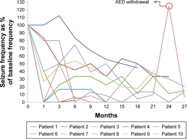
Seizure frequencies over time after DBS implantation, expressed as percentage of that at baseline.
Notes: Patient 8 showed an abrupt increase in seizure frequency, during voluntary AED withdrawal. After restarting medication, the seizure frequency was restored to baseline.
Abbreviations: AED, antiepileptic drug; DBS, deep brain stimulation.
Spatiotemporal source analysis
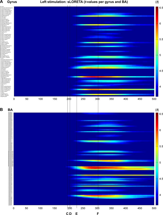
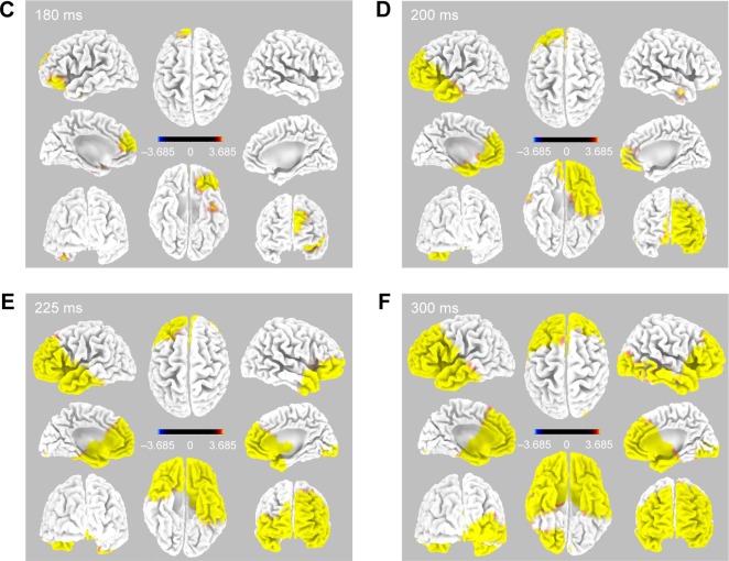
Immediately after CM stimulation at 5 Hz, the sequentially activated cortical areas were visualized using the spatiotemporal sLORETA method. The areas activated with statistical significance (p<0.05) were marked on a spatiotemporal source map (by gyrus and Brodmann area [BA]) and a 3D-MNI cortical map. After left electrode stimulation (Figure 2), the activation of the left orbital gyrus (180 ms, BA47) was followed by that of the left prefrontal (BA47, 45, 46, 10, and 11) and anterior temporal (BA38) areas (200 ms). At 200 ms, the mid subcallosal, bilateral anterior cingulate (BA25, 32) and right medial pole of frontal (BA10, 11) regions were activated, which evolved diffusely into the right frontal (BA46, 45) and temporal (BA38) areas (225 and 300 ms).
Figure 2.
Time-dependent spatiotemporal cortical activation pattern on left CM stimulation assessed by sLORETA.
Notes: Spatiotemporal source maps, showing the color coded t-values of individual gyrus (A) and BA (B) over the time course immediately after initiation of 5 Hz stimulation. The t-values >3.685 are significant at a level of p<0.05. 3D reconstructions at selected time points (C–F).
Abbreviations: 3D, three dimensional; BA, Brodmann area; CM, centromedian thalamic nucleus; L, left; R, right; sLORETA, standardized low-resolution brain electrotomography.
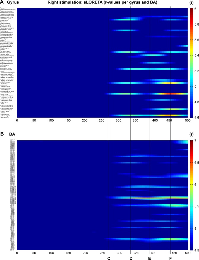
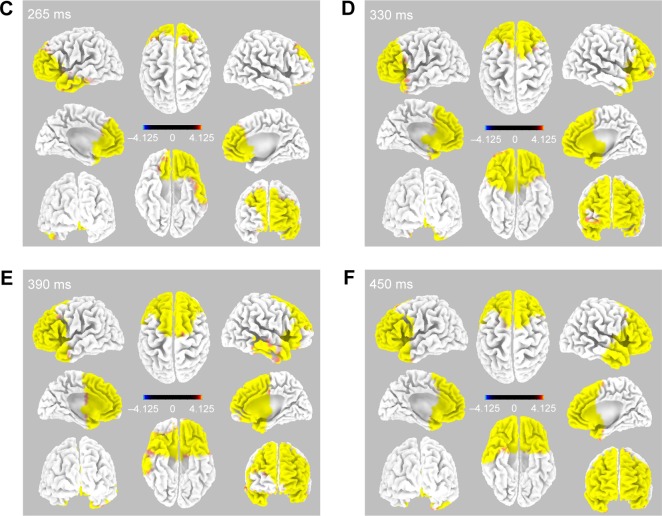
During right electrode stimulation (Figure 3), activation of the bilateral anterior cingulate (BA25, 32) and prefrontal gyrus (BA10, 11, 45, and 46) was followed by that of both the dorsolateral and anterior temporal areas.
Figure 3.
Time-dependent spatiotemporal cortical activation pattern on right CM stimulation assessed by sLORETA.
Notes: Spatiotemporal source maps, showing the color coded t-values of individual gyrus (A) and BA (B) over the time course immediately after initiation of 5 Hz stimulation. The t-values >4.6 are significant at a level of p<0.05. 3D reconstructions at selected time points (C–F).
Abbreviations: 3D, three dimensional; BA, Brodmann area; CM, centromedian thalamic nucleus; L, left; R, right; sLORETA, standardized low-resolution brain electrotomography.
Source distribution of CR
Left stimulation
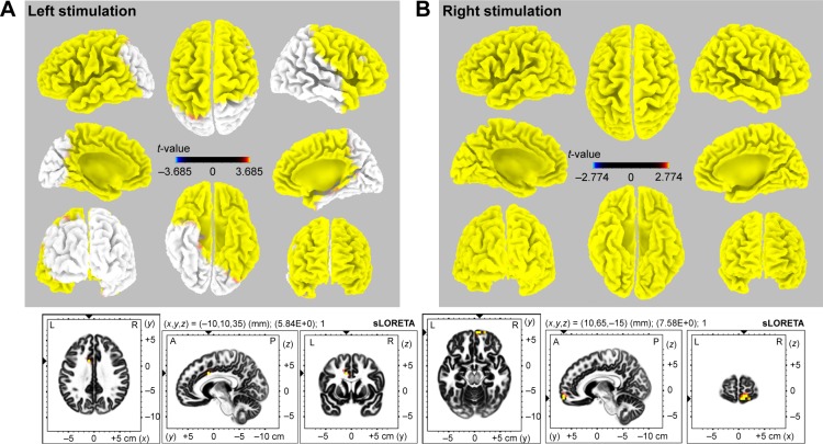
The sLORETA solution showed a statistically significantly activated cortical area in the bilateral frontal, left temporal, and right anterior temporal areas (Figure 4, left upper; p<0.05, t-value 3.685). There were no regions of decreased activation compared to baseline. The most activated area was the left cingulate gyrus (Figure 4, left lower; t-value 5.84, p<0.01, MNI coordinate −10, 10, 35). In addition, the contralateral cingulate area was significantly activated (p<0.01, t-value 5.34, MNI coordinate 10, 10, 35; image not shown).
Figure 4.
3D map of sLORETA images demonstrates the statistically significant activated area with CR.
Notes: Left stimulation (A): bilateral frontal, left temporal, and right anterior temporal areas were activated (p<0.05, t-value 3.685). The maximal activation was observed at the left cingulate gyrus (t-value 5.84, p<0.01, MNI coordinate -10, 10, 35). Right stimulation (B): diffuse cortical areas were activated (p<0.05, t-value 2.774). The maximal activation was found at the right medial frontal gyrus (t-value 7.58, p<0.01, MNI coordinate 10, 65, -15).
Abbreviations: 3D, three dimensional; A, anterior; CR, cortical recruiting response; L, left; MNI, Montreal Neurological Institute; P, posterior; R, right; sLORETA, standardized low-resolution brain electrotomography.
Right stimulation
The whole cortical area showed significant activation during stimulation (Figure 4, right upper; p<0.05, t-value 2.774). Decreased activated regions were not seen during right electrode stimulation. The most prominent activation was in the medial frontal gyrus (Figure 4, right lower; t-value 7.58, p<0.01, MNI coordinate 10, 65, −15). In addition, we observed significant activation of the contralateral mirror site (MNI coordinate −10, 65, −15, t-value 7.08; image not shown).
Probabilistic tractography
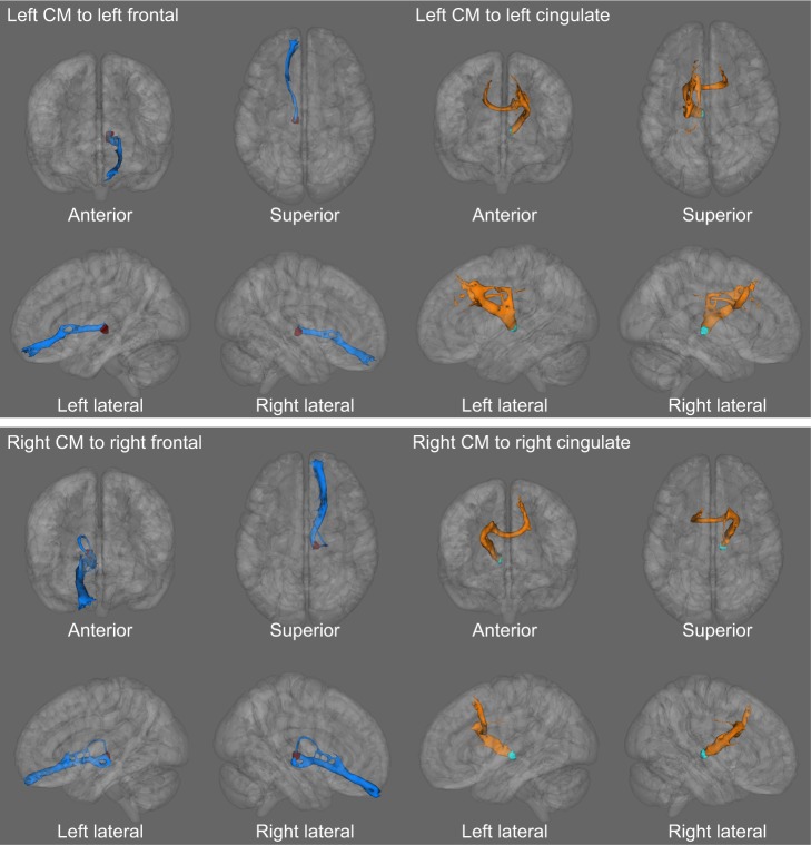
From the averaged tractography across all 10 subjects, we could observe two patterns in the white matter tract from the CM in our probabilistic DTI–tractography analysis. One pattern projected from the CM through the inferior and medial frontal regions. The other tract ran from the CM via the anterior cingulate gyrus toward the bilateral superomedial frontal gyri (Figure 5). The inferomedial frontal fiber showed only an ipsilateral connection. In contrast, the cingulate fiber ran to not only the ipsilateral frontal area (superior and medial frontal gyri) but also the contralateral mirror site (superior and medial frontal gyri) through the anterior corpus callosal pathway.
Figure 5.
The probabilistic tractography illustrates a significant microstructural connection from CM to cingulate and medial frontal gyrus.
Notes: The medial frontal fiber shows more connecting distribution in the ipsilateral hemisphere. The cingulate fiber runs not only to ipsilateral frontal area (superior and medial frontal gyri) but also to contralateral frontal regions (superior and medial frontal gyri).
Abbreviation: CM, centromedian thalamic nucleus.
Discussion
Bilateral CM DBS could be a good treatment option for intractable epilepsy patients who are unsuitable for resective surgery. Velasco et al reported treating 13 intractable epilepsy patients with CM DBS, which induced significant seizure reduction and attenuation of frontal spikes and waves. They also mentioned that generalized tonic-clonic and atypical absence seizures were markedly attenuated but focal seizures were not after CM DBS.5,6 Valentin et al reported the effect of CM DBS in six GE and five FLE patients. The generalized group showed an 81% seizure reduction; however, the FLE group saw only a 10% reduction 1 year after DBS implantation.4 In the present study, however, the FE group showed a mean seizure reduction of 80.3%, which is higher than that reported in previous studies.4–6 The discrepancy is attributed to the inconsistent patient selection, diverse stimulation parameters, or inhomogeneous target sites of DBS electrodes across the studies.
Some previous studies suggested that CR could be a predictor for good outcomes or exact electrode position. Theoretically, CR itself reflects a pattern of activation in the nonspecific thalamic nucleus that projects to diffuse cortical areas;20 however, we previously reported a patient with bilateral temporal lobe epilepsy who experienced proper CR after the repositioning of an ATN-DBS electrode.10 He achieved the most favorable condition: seizure-free state for >2 years (data not shown). Velasco et al12 previously suggested that the predictors of a good outcome after CM-DBS were case selection, exact electrode insertion, and CR upon stimulation.21
The selection of the optimal stimulation target and the long-term clinical effects of DBS in treating epilepsy remain still elusive. Nevertheless, our results suggest that optimal stimulation of CM-DBS could be an effective treatment option for patients with focal, intractable epilepsy.
Analysis of CR and cortical activation with CM-DBS stimulation
In this study, we used EEG source analysis to investigate the changes in cortical activation by DBS stimulation. EEG source analysis has been widely used to define ictal focus or propagation patterns.22–24 In mesial temporal lobe epilepsy, the cortical source distributions differ with the initial ictal discharge, and a 5–13 Hz ictal source correlated with the ictal onset zone.24 In another study with stereo-EEG (SEEG) and ictal source analysis, the source localization methods well correlated with ictal onset and the SEEG propagation pattern.25
A few studies had investigated the connectivity between the thalamic nucleus and variable cerebral structures by analyzing the CR pattern and source analysis techniques.8,9,26 Whereas cortical activation was seen in the ipsilateral cingulate, insula, and lateral temporal cortex during ATN stimulation, CM stimulation induced a more diffuse activation pattern, which suggests the importance of choosing the optimal stimulation site for DBS.9 The CM has diffuse cortical connections and modulates the reticulo–thalamo–cortical system,27,28 which has a relationship with wakefulness, attention, and cortical excitability associated with the propagation and generalization of ictal discharge.28
In the present study, aside from the wide cortical connection from CM, we identified two maximally activated regions in the medial prefrontal and cingulate gyri. These results imply that CM stimulation induced bilateral diffuse cortical activation, first through the cingulate and medial prefrontal gyri with subsequent widespread propagation.
Structural connectivity (DTI tractography)
We performed tractography between CM and maximal activated areas, which are defined by EEG source analysis of CR. Multimodal imaging and source analysis techniques have lately been introduced to both define the structural connectivity between EEG sources and demonstrate ictal propagation patterns. A recent study showed that DTI tractography could reveal a fiber connection between the source of an EEG and the magnetoencephalography spike.29 In our study, we illustrated the structural connection from the CM to the medial frontal gyrus and anterior cingulate cortex (ACC). The tract of the ACC propagated to the frontal cortex bilaterally, rather than unilaterally. Our result implies that the ACC seems to be a hub structure for diffuse propagation of CM stimulation.
The ACC is part of the limbic system, which is related to affection, cognitive function, and seizure propagation.30 The ACC has medial thalamic connections that might play a pivotal role in the remote control of seizure synchronization and modulation. In GE patients, an EEG-informed fMRI study reported that the generation and propagation of generalized spike and wave discharges was related to the cingulate, medial frontal cortex, and thalamic nucleus.31 These results suggested that the ACC could be a key structure in the initiation and propagation of ictal discharges that could be blocked efficiently with CM or other thalamic DBS.
Limitations
Our study has some limitations. The number of participants is too small to draw a strong conclusion. We obtained EEG data from only 19 electrodes; hence, the highest resolution of sLORETA localization was not available. In addition, we faced important limitations with respect to obtaining high- resolution EEG data in our postoperative clinical setting (wound, dressing materials, and patient condition). To minimize the influence of EEG artifact, all EEG data were obtained under the same condition (after DBS electrode insertion with external stimulation, unified EEG data acquisition under the same protocol in the epilepsy monitoring unit setting).
We enrolled five patients with structural brain abnormalities (four schizencephaly and one heterotopia). Tractography was performed in each patient’s own MRI space, but the EEG source analysis was performed using a normal MRI template provided by the sLORETA toolkit. In this study, however, we intended to investigate the propagation pattern of stimulation by using a statistical method in the standard MNI space. A recent study performed EEG source analysis for patients with structural abnormality. They reported that the irritative zone of schizencephaly correlated to the current source distribution of the interictal epileptiform discharge.32 Therefore, our selected methods for analyzing the EEG and MRI data seem to be appropriate and concordant with our original purpose.
Conclusion
We found CM-DBS to be a good alternative treatment option for both generalized and FE patients. Our results suggest that the selection of optimal electrodes is tightly related to clinical effect, and CR may be a convincing biomarker in the optimal targeting of DBS electrodes in drug-refractory epilepsy candidates. The multimodal analysis using EEG and DTI tractography revealed that the ACC could be a key region related to both functional propagation and structural coupling from CM-DBS for epilepsy. In addition, CM-DBS seems to modulate the neural network and influence cortical EEG activation through diffuse but predominantly thalamo–prefrontal and thalamo–cingulate connections. Our results provide new insight elucidating the therapeutic mechanisms of CM-DBS. Further study including large numbers of subjects and more exquisite EEG data is warranted.
Supplementary materials
Mask of CM that is target of DBS insertion.
Notes: The CM mask used as a seed point of tractography analysis. The target coordinates for the CM nucleus were as follows: 10 mm lateral from midline, 1 mm anterior to the PC, and 1 mm above the ICL. We made the CM mask (8 mm3 volume) in a standard MNI space using FSLView (version 3.2.0, FMRIB Centre, University of Oxford, Oxford, UK).
Abbreviations: CM, centromedian thalamic nucleus; DBS, deep brain stimulation; ICL, intercommissural line; MNI, Montreal Neurological Institute; PC, posterior commissure.
We defined the maximally activated cortical area as the highest t-value in source analysis of “EEG with maximal CR”.
Notes: The cingulate gyrus (left stimulation, t-value 5.84, p<0.01, MNI coordinate -10, 10, 35) and medial frontal gyrus (right stimulation, t-value 7.58, p<0.01, MNI coordinate 10, 65, -15) showed the highest t-value with stimulation. The contralateral mirror site (cingulate gyrus: MNI coordinates 10, 10, 35; medial frontal gyrus: MNI coordinates -10, 65, -15) was used for analysis of bilateral connection. To make the waypoint mask for tractography we set the 5 mm3 cube-ROI mask which centered each point and did not include the CSF or skull.
Abbreviations: CR, cortical recruiting response; CSF, cerebrospinal fluid; EEG, electroencephalogram; MNI, Montreal Neurological Institute; ROI, region of interest.
References
- 1.Velasco F, Velasco M, Jimenez F, et al. Predictors in the treatment of difficult-to-control seizures by electrical stimulation of the centromedian thalamic nucleus. Neurosurgery. 2000;47(2):295–304. doi: 10.1097/00006123-200008000-00007. discussion 304–305. [DOI] [PubMed] [Google Scholar]
- 2.Choi JG, Kim SH, Lee SH, et al. Variability of the target coordinates in thalamic deep brain stimulation for epilepsy, review. J Kor Soc Ster Func Neurosurg. 2015;11:53–59. [Google Scholar]
Acknowledgments
This research was supported by a grant of the Korea Health Technology R&D Project through the Korea Health Industry Development Institute (KHIDI), funded by the Ministry of Health & Welfare, Republic of Korea (grant number: HI16C1643).
Footnotes
Disclosure
The authors report no conflicts of interest in this work.
References
- 1.Kwan P, Brodie MJ. Early identification of refractory epilepsy. N Engl J Med. 2000;342(5):314–319. doi: 10.1056/NEJM200002033420503. [DOI] [PubMed] [Google Scholar]
- 2.Engel J, Jr, Wiebe S, French J, et al. Practice parameter: temporal lobe and localized neocortical resections for epilepsy. Epilepsia. 2003;44(6):741–751. doi: 10.1046/j.1528-1157.2003.48202.x. [DOI] [PubMed] [Google Scholar]
- 3.Klinger NV, Mittal S. Clinical efficacy of deep brain stimulation for the treatment of medically refractory epilepsy. Clin Neurol Neurosurg. 2016;140:11–25. doi: 10.1016/j.clineuro.2015.11.009. [DOI] [PubMed] [Google Scholar]
- 4.Valentin A, Garcia Navarrete E, Chelvarajah R, et al. Deep brain stimulation of the centromedian thalamic nucleus for the treatment of generalized and frontal epilepsies. Epilepsia. 2013;54(10):1823–1833. doi: 10.1111/epi.12352. [DOI] [PubMed] [Google Scholar]
- 5.Velasco F, Velasco M, Jimenez F, et al. Predictors in the treatment of difficult-to-control seizures by electrical stimulation of the centromedian thalamic nucleus. Neurosurgery. 2000;47(2):295–304. doi: 10.1097/00006123-200008000-00007. discussion 304–305. [DOI] [PubMed] [Google Scholar]
- 6.Velasco AL, Velasco F, Jimenez F, et al. Neuromodulation of the centro-median thalamic nuclei in the treatment of generalized seizures and the improvement of the quality of life in patients with Lennox-Gastaut syndrome. Epilepsia. 2006;47(7):1203–1212. doi: 10.1111/j.1528-1167.2006.00593.x. [DOI] [PubMed] [Google Scholar]
- 7.Wakerley B, Schweder P, Green A, Aziz T. Possible seizure suppression via deep brain stimulation of the thalamic ventralis oralis posterior nucleus. J Clin Neurosci. 2011;18(7):972–973. doi: 10.1016/j.jocn.2010.10.018. [DOI] [PubMed] [Google Scholar]
- 8.Zumsteg D, Lozano AM, Wennberg RA. Rhythmic cortical EEG synchronization with low frequency stimulation of the anterior and medial thalamus for epilepsy. Clin Neurophysiol. 2006;117(10):2272–2278. doi: 10.1016/j.clinph.2006.06.707. [DOI] [PubMed] [Google Scholar]
- 9.Zumsteg D, Lozano AM, Wieser HG, Wennberg RA. Cortical activation with deep brain stimulation of the anterior thalamus for epilepsy. Clin Neurophysiol. 2006;117(1):192–207. doi: 10.1016/j.clinph.2005.09.015. [DOI] [PubMed] [Google Scholar]
- 10.Kim SH, Son BC, Lim SC, Kim WJ, Bae DW, Shon YM. EEG driving response during low-frequency stimulation of anterior thalamic nucleus: is it a good predictor of the correct location of DBS electrode? Clin Neurophysiol. 2014;125(5):1065–1066. doi: 10.1016/j.clinph.2013.09.010. [DOI] [PubMed] [Google Scholar]
- 11.Hodaie M, Wennberg RA, Dostrovsky JO, Lozano AM. Chronic anterior thalamus stimulation for intractable epilepsy. Epilepsia. 2002;43(6):603–608. doi: 10.1046/j.1528-1157.2002.26001.x. [DOI] [PubMed] [Google Scholar]
- 12.Velasco M, Velasco F, Velasco AL. Centromedian-thalamic and hippocampal electrical stimulation for the control of intractable epileptic seizures. J Clin Neurophysiol. 2001;18(6):495–513. doi: 10.1097/00004691-200111000-00001. [DOI] [PubMed] [Google Scholar]
- 13.Augustine JR. Human Neuroanatomy. Burlington, MA: Academic Press; 2008. [Google Scholar]
- 14.Pascual-Marqui RD. Standardized low-resolution brain electromagnetic tomography (sLORETA): technical details. Methods Find Exp Clin Pharmacol. 2002;24(suppl D):5–12. [PubMed] [Google Scholar]
- 15.Mazziotta J, Toga A, Evans A, et al. A probabilistic atlas and reference system for the human brain: international consortium for brain mapping (ICBM) Philos Trans R Soc Lond B Biol Sci. 2001;356(1412):1293–1322. doi: 10.1098/rstb.2001.0915. [DOI] [PMC free article] [PubMed] [Google Scholar]
- 16.Lancaster JL, Woldorff MG, Parsons LM, et al. Automated Talairach atlas labels for functional brain mapping. Hum Brain Mapp. 2000;10(3):120–131. doi: 10.1002/1097-0193(200007)10:3<120::AID-HBM30>3.0.CO;2-8. [DOI] [PMC free article] [PubMed] [Google Scholar]
- 17.Choi JG, Kim SH, Lee SH, et al. Variability of the target coordinates in thalamic deep brain stimulation for epilepsy, review. J Kor Soc Ster Func Neurosurg. 2015;11:53–59. [Google Scholar]
- 18.Bender B, Mänz C, Korn A, Nägele T, Klose U. Optimized 3D magnetization-prepared rapid acquisition of gradient echo: identification of thalamus substructures at 3T. AJNR Am J Neuroradiol. 2011;32(11):2110–2115. doi: 10.3174/ajnr.A2705. [DOI] [PMC free article] [PubMed] [Google Scholar]
- 19.Fischl B, Dale AM. Measuring the thickness of the human cerebral cortex from magnetic resonance images. Proc Natl Acad Sci U S A. 2000;97(20):11050–11055. doi: 10.1073/pnas.200033797. [DOI] [PMC free article] [PubMed] [Google Scholar]
- 20.Osorio I. Recruitment responses have no localizing value. Clin Neurophysiol. 2015;126(3):644. doi: 10.1016/j.clinph.2014.05.026. [DOI] [PubMed] [Google Scholar]
- 21.Son BC, Shon YM, Choi JG, et al. Clinical outcome of patients with deep brain stimulation of the centromedian thalamic nucleus for refractory epilepsy and location of the active contacts. Stereotact Funct Neurosurg. 2016;94(3):187–197. doi: 10.1159/000446611. [DOI] [PubMed] [Google Scholar]
- 22.Holmes MD, Quiring J, Tucker DM. Evidence that juvenile myoclonic epilepsy is a disorder of frontotemporal corticothalamic networks. Neuroimage. 2010;49(1):80–93. doi: 10.1016/j.neuroimage.2009.08.004. [DOI] [PubMed] [Google Scholar]
- 23.Strobbe G, Carrette E, Lopez JD, et al. Electrical source imaging of inter-ictal spikes using multiple sparse volumetric priors for presurgical epileptogenic focus localization. Neuroimage Clin. 2016;11:252–263. doi: 10.1016/j.nicl.2016.01.017. [DOI] [PMC free article] [PubMed] [Google Scholar]
- 24.Lee EM, Shon YM, Jung KY, et al. Low resolution electromagnetic tomography analysis of ictal EEG patterns in mesial temporal lobe epilepsy with hippocampal sclerosis. Clin Neurophysiol. 2009;120(10):1797–1805. doi: 10.1016/j.clinph.2009.08.003. [DOI] [PubMed] [Google Scholar]
- 25.Koessler L, Benar C, Maillard L, et al. Source localization of ictal epileptic activity investigated by high resolution EEG and validated by SEEG. Neuroimage. 2010;51(2):642–653. doi: 10.1016/j.neuroimage.2010.02.067. [DOI] [PubMed] [Google Scholar]
- 26.Zumsteg D, Lozano AM, Wennberg RA. Depth electrode recorded cerebral responses with deep brain stimulation of the anterior thalamus for epilepsy. Clin Neurophysiol. 2006;117(7):1602–1609. doi: 10.1016/j.clinph.2006.04.008. [DOI] [PubMed] [Google Scholar]
- 27.Jasper HH. Current evaluation of the concepts of centrencephalic and cortico-reticular seizures. Electroencephalogr Clin Neurophysiol. 1991;78(1):2–11. doi: 10.1016/0013-4694(91)90012-s. [DOI] [PubMed] [Google Scholar]
- 28.Velasco M, Velasco F, Velasco AL, Jiménez F, Brito F, Márquez I. Acute and chronic electrical stimulation of the centromedian thalamic nucleus: modulation of reticulo-cortical systems and predictor factors for generalized seizure control. Arch Med Res. 2000;31(3):304–315. doi: 10.1016/s0188-4409(00)00085-0. [DOI] [PubMed] [Google Scholar]
- 29.Tanaka N, Grant PE, Suzuki N, et al. Multimodal imaging of spike propagation: a technical case report. AJNR Am J Neuroradiol. 2012;33(6):E82–E84. doi: 10.3174/ajnr.A2701. [DOI] [PMC free article] [PubMed] [Google Scholar]
- 30.Walker J, Storch G, Quach-Wong B, Sonnenfeld J, Aaron G. Propagation of epileptiform events across the corpus callosum in a cingulate cortical slice preparation. PLoS One. 2012;7(2):e31415. doi: 10.1371/journal.pone.0031415. [DOI] [PMC free article] [PubMed] [Google Scholar]
- 31.Zhang CH, Sha Z, Mundahl J, et al. Thalamocortical relationship in epileptic patients with generalized spike and wave discharges – a multimodal neuroimaging study. Neuroimage Clin. 2015;9:117–127. doi: 10.1016/j.nicl.2015.07.014. [DOI] [PMC free article] [PubMed] [Google Scholar]
- 32.Kim DH, Kwon OY, Jung SW, et al. Location of irritative zone in epileptic brains of schizencephalic patients. Clin EEG Neurosci. 2016;47(3):235–242. doi: 10.1177/1550059414548859. [DOI] [PubMed] [Google Scholar]
Associated Data
This section collects any data citations, data availability statements, or supplementary materials included in this article.
Supplementary Materials
Mask of CM that is target of DBS insertion.
Notes: The CM mask used as a seed point of tractography analysis. The target coordinates for the CM nucleus were as follows: 10 mm lateral from midline, 1 mm anterior to the PC, and 1 mm above the ICL. We made the CM mask (8 mm3 volume) in a standard MNI space using FSLView (version 3.2.0, FMRIB Centre, University of Oxford, Oxford, UK).
Abbreviations: CM, centromedian thalamic nucleus; DBS, deep brain stimulation; ICL, intercommissural line; MNI, Montreal Neurological Institute; PC, posterior commissure.
We defined the maximally activated cortical area as the highest t-value in source analysis of “EEG with maximal CR”.
Notes: The cingulate gyrus (left stimulation, t-value 5.84, p<0.01, MNI coordinate -10, 10, 35) and medial frontal gyrus (right stimulation, t-value 7.58, p<0.01, MNI coordinate 10, 65, -15) showed the highest t-value with stimulation. The contralateral mirror site (cingulate gyrus: MNI coordinates 10, 10, 35; medial frontal gyrus: MNI coordinates -10, 65, -15) was used for analysis of bilateral connection. To make the waypoint mask for tractography we set the 5 mm3 cube-ROI mask which centered each point and did not include the CSF or skull.
Abbreviations: CR, cortical recruiting response; CSF, cerebrospinal fluid; EEG, electroencephalogram; MNI, Montreal Neurological Institute; ROI, region of interest.


