

Abstract
Background There is a paucity of information on the microstructure of the distal radius, and how this relates to its morphology and function.
Purpose This study aims to assess the microanatomical structure of the distal radius, and relate this to its morphology, function, and modes of failure.
Methods Six dry adult skeletal distal radii were examined with microcomputed tomography scan and analyzed with specialist computer software. From 3D and 2D images, the subchondral, cortical, and medullary trabecular were assessed and interpreted based on the overall morphology of the radius.
Results The expanded distal radial metaphysis provides a wide articular surface for distributing the articular load. The extrinsic wrist ligaments are positioned around the articular perimeter, except on the dorsal radial corner. The subchondral bone plate is a 2 mm multilaminar lattice structure, which is thicker below the areas of the maximal articular load. There are spherical voids distally, which become ovoid proximally, which assist in absorbing articular impact. It does not have Haversian canals. From the volar aspect of the lunate facet, there are thick trabecular columns that insert into the volar cortex of the radius at the metaphyseal–diaphyseal junction. For the remainder of the subchondral bone plate, there is an intermediate trabecular network, which transmits the load to the intermediate trabeculae and then to the trabecular arches. The arches pass proximally and coalesce with the ridges of the diaphyseal cortex.
Conclusion The distal radius morphology is similar to an arch bridge. The subchondral bone plate resembles the smooth deck of the bridge that interacts with the mobile load. The load is transmitted to the rim, intermediate struts, and arches. The metaphyseal arches allow the joint loading forces to be transmitted proximally and laterally, providing compression at all levels and avoiding tension. The arches have a natural ability to absorb the impact which protects the articular surface. The distal radius absorbs and transmits the articular impact to the medullary cortex and intermediate trabeculae. The medullary arches are positioned to transmit the load from the intermediate trabeculae to the diaphysis.
Clinical Relevance The microstructure of the distal radius is likely to be important for physiological loading of the radius. The subchondral bone plate is a unique structure that is different to the cancellous and cortical bone. All three bone types have different functions. The unique morphology and microstructure of the distal radius allow it to transmit load and protect the articular cartilage.
Keywords: distal radius, fracture, ultrastructure, microarchitecture, micro-CT
The gross anatomy of the distal radius has been studied for centuries. 1 Ultrastructure studies, (e.g., histomorphometry) have recently become popular, and include a volumetric analysis, comparing the trabecular density with the occurrence of fragility fractures in osteoporosis. 2 Singh et al reported the basic trabecular structure of the proximal femur in 1970. 3 This has been valued, as it provided a basic model of the mechanical properties of the femur and assisted in understanding its modes of failure.
The metaphysis of the distal radius is composed principally of cancellous bone which transmits most of the load of this region. 4 Previous research on the distal radius has been limited to its gross anatomy and ultrastructure. 4 5 6 There is a paucity of research on the microstructure of the distal radius. A better understanding of the trabecular microstructure would provide a better appreciation of its contribution to resist impact, transmit load and its mode of failure. The aim of this study is to assess the microstructure of the distal radius and relate it to the gross morphology, function, and failure.
Methods
Specimens
Six dry cadaveric human distal radii from the Ray Last Laboratories were scanned with the SkyScan 1076 (Skyscan, Kontich, Belgium), to create microcomputed tomography (CT) images with a resolution of 18 µm. Reconstructive images were created in the coronal, sagittal, and axial planes using CTan and CTvol (Skyscan). Volume-rendered images were created using ParaView open source software (available at: www.paraview.org/ , Kitware Inc.).
Interpretation
The gross anatomical structure was assessed, and measurements were taken. The cortical thickness of the anatomical regions was measured, including the subchondral bone plate, medulla, and cortex. The orientation of the metaphyseal medullary trabecular pattern was assessed.
The results were interpreted with regard to the overall morphology, function, and failure modes of the distal radius. Program R (available at: www.r-project.org ), was used for statistical analysis. Unpaired t -test was used to compare measurements.
Results
Gross Anatomy
The distal radius consists of the subchondral bone plate, the thickened cortical bone, and the medullary trabecular bone.
Dimensions
The measured dimensions of the radii are presented in Tables 1 and 2 , and the method of measurement shown in Fig. 1 . The metaphyseal radius flares from the diaphysis to provide a broad load-bearing surface for the carpus. There are tuberosities for the multiple ligament attachments, which encircle the articular surface, except on the dorsoradial aspect. 7 8 9 10
Table 1. Dimensions of the distal radius in the axial plane at Lister's tubercle, and 1 cm proximal.
| Radius | Lister's tubercle | 1 cm proximal to Lister's tubercle | ||||||
|---|---|---|---|---|---|---|---|---|
| Axial plane | Medial–lateral | Axial plane | Medial–lateral | |||||
| Cortex–cortex | Intramedullary | Cortex–cortex | Intramedullary | Cortex–cortex | Intramedullary | Cortex–cortex | Intramedullary | |
| 1 | 19.4 (3) | 18.8 | 27.5 (1) | 27.1 | 13.4 (12) | 11.8 | 21.8 (9) | 19.9 |
| 2 | 23.3 (3) | 22.7 | 29.9 (2) | 29.4 | 15.9 (14) | 13.7 | 22.8 (7) | 21.3 |
| 3 | 20.3 (1) | 20.0 | 25.4 (2) | 25.0 | 13.8 (7) | 12.8 | 19.0 (3) | 18.5 |
| 4 | 22.2 (1) | 21.9 | 26.3 (2) | 25.7 | 15.1 (5) | 14.4 | 21.0 (3) | 20.4 |
| 5 | 21.6 (2) | 21.2 | 28.8 (1) | 28.5 | 16.3 (8) | 15.0 | 25.9 (5) | 24.6 |
| 6 | 23.4 (1) | 23.2 | 31.4 (1) | 31.0 | 16.8 (2) | 16.4 | 25.8 (1) | 25.5 |
| Mean | 21.7 (2) | 21.3 | 28.2 (1) | 27.8 | 15.2 (8) | 14.0 | 22.7 (4) | 21.7 |
| Standard deviation | 1.47 | 1.52 | 2.06 | 2.08 | 1.26 | 1.49 | 2.49 | 2.52 |
Note: Measurements are in millimeter. Cortex—cortex represents the dimensions from the furthest part of the cortices. Percentage of the cortex compared with the total distance is given as a percentage in brackets. “Intramedullary” distance represents the distance between from the inner cortices.
Table 2. Dimensions of the volar and dorsal cortices taken at the level of Lister's tubercle, and 1 cm proximal.
| Radius | Cortex width at Lister's tubercle | Cortex width 1 cm proximal to Lister's tubercle | ||
|---|---|---|---|---|
| Volar | Dorsal | Volar | Dorsal | |
| 1 | 0.35 | 0.24 | 0.87 | 0.73 |
| 2 | 0.28 | 0.24 | 1.14 | 1.04 |
| 3 | 0.14 | 0.10 | 0.55 | 0.45 |
| 4 | 0.17 | 0.14 | 0.38 | 0.35 |
| 5 | 0.21 | 0.17 | 0.76 | 0.55 |
| 6 | 0.14 | 0.10 | 0.28 | 0.17 |
| Mean | 0.21 | 0.17 | 0.66 | 0.55 |
| Standard deviation | 0.08 | 0.06 | 0.29 | 0.28 |
Note: All the measurements are given in millimeter.
Fig. 1.

A sequence of axial images was calibrated using ImageJ. A point at the most prominent aspect of Lister's tubercle was identified. A further point 1 cm proximal to this was used to represent the metadiaphyseal junction of the radius. ( A ) “Cortex-cortex” measurements were taken from the furthest point of each cortex. ( B ) “Intramedullary” distance represents the distance between from the inner cortices. This process was repeated for each of the six radii.
The metaphyseal bone has a thin cortex, which progressively thickens proximally to form the diaphysis. The volar cortex is thicker both at Lister's tubercle and 1 cm proximal compared with the dorsal cortex at these points, but this did not reach statistical significance ( p = 0.28 and 0.54, respectively). The percentage width of cortex compared with intramedullary canal increased proximal to Lister's tubercle. Both the volar and dorsal cortices were significantly thicker at this point ( p = 0.018 and 0.027, respectively).
Subchondral Bone Plate
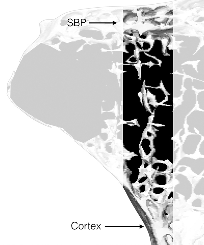
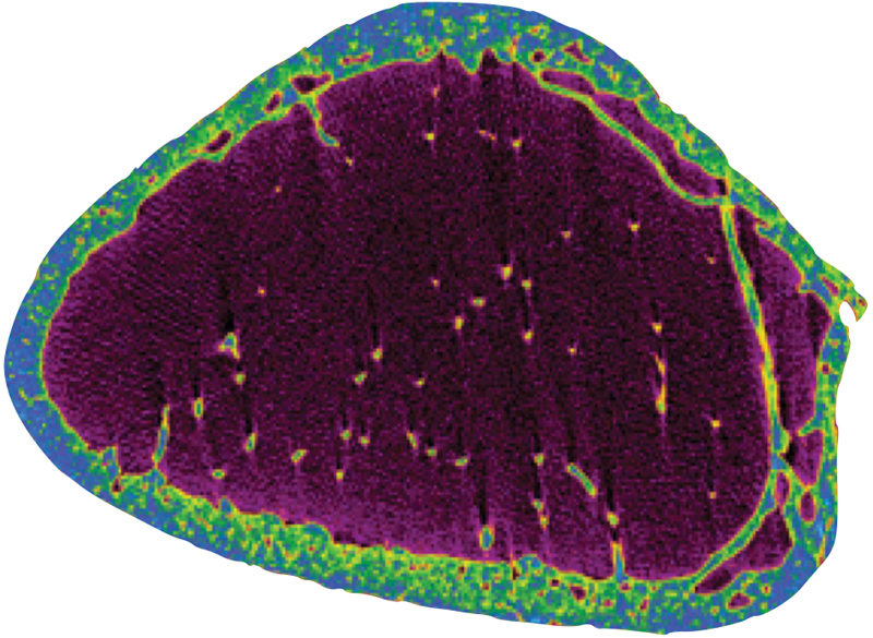
Subchondral bone plate (SBP) has a lattice configuration, with multiple parallel lamina ( Fig. 2 ). The mean measured thickness of the SBP was 1.97 mm (2.009, 1.638, 1.896, 1.946, 2.005, and 2.297 mm). The thickness of the SBP and the number of laminations is greatest at the sites of articular load bearing. The superficial layer spans across the entire articular surface to the opposite cortical margin. We refer to this as the “primary” subchondral bone plate. The other layers do not span the entire articular surface. We refer to these as the “secondary, tertiary, etc.” layers, respectively. The arrangement of the multiple layers is similar to a leaf spring, which is still used for suspension in heavy motor vehicles.
Fig. 2.
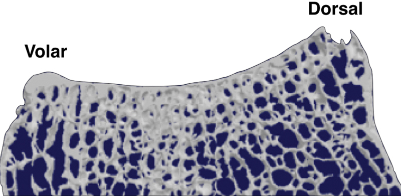
Sagittal section of the distal radius showing the subchondral bone plate.
Between the layers of the SBP are multiple interlaminar osseous struts ( Fig. 3 ). Between the primary and secondary laminae, the struts are perpendicular to the articular surface. As we move away from the primary subchondral bone plate, the struts are directed more along the line of the radial shaft. Between the trabecular struts, there are voids in the bone. Between the primary and secondary subchondral bone plate, they are spherical (isotropic). As we move away from the articular surface, the voids become elliptical and axially oriented (anisotropic). No Haversian canals were identified, in the subchondral bone plate in any specimen.
Fig. 3.
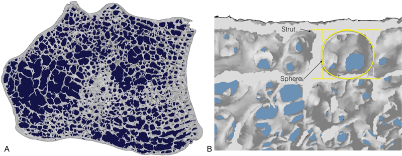
( A–B ) Axial section of the distal radius. Ultrastructure shows trabecular struts arising perpendicular and between the laminae within this plate. A sphere-shaped void is present between the laminae and struts.
Medullary Trabecular Bone
The trabeculae of the metaphysis are configured principally as plates, and where these coalesce, there is a thickened rod. Trabecular plates are also seen to span and brace across the angle of the radial tuberosity. The rods extend proximally and become the longitudinal ridges on the endosteal surface of the metaphyseal–diaphyseal radius ( Fig. 4 ).
Fig. 4.
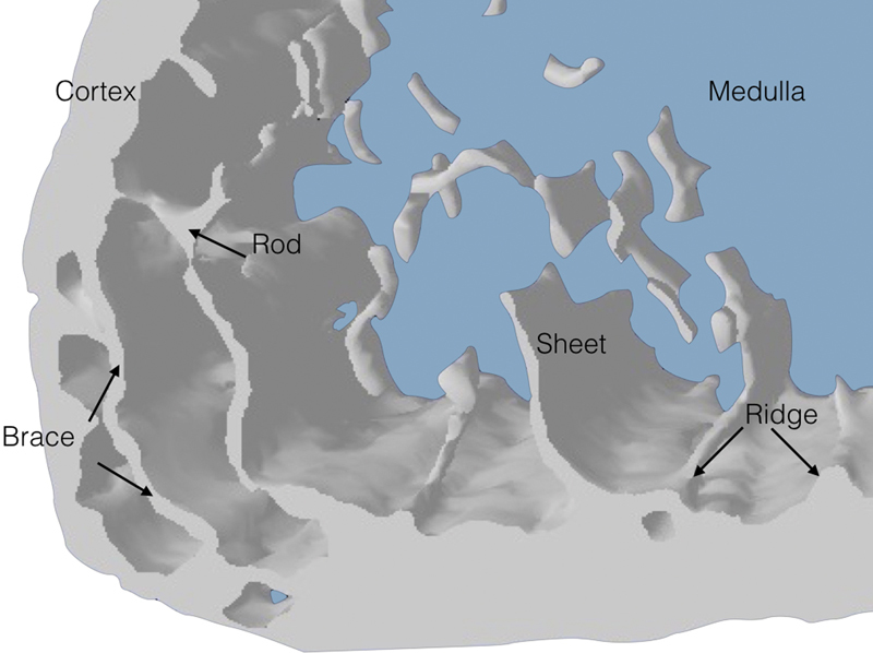
Axial section through the distal radius illustrating braces reinforcing thickened zones in the cortical pillars. Rods, sheets, and ridges are shown.
Sagittal Plane
On the sagittal image of the lunate facet, there is a marked prominence that overhangs the volar aspect of the radius ( Fig. 5 ). This allows the load-bearing area of the lunate facet to more volar than the scaphoid facet. From the main load-bearing area of the lunate facet, there are multiple thick trabecular columns, which are parallel to the shaft of the radius and span to the thick volar cortex at the diaphyseal–metaphyseal junction. The load-bearing aspect of the lunate facet, the trabecular columns, and the volar cortex of the radial shaft are all colinear.
Fig. 5.
Sagittal section through the lunate fossa of the distal radius.
Also on the sagittal image of the lunate facet can be seen a dorsal trabeculae pattern, which commences adjacent to the columns of the lunate facet ( Fig. 5 ). These span from just dorsal to the main load-bearing aspect of the lunate facet, to the dorsal endosteal surface. The dorsal trabeculae have a curve in the shape of a gothic arch. Proximal to the arch there is a relative void of trabecular bone. In a church, the open space below the structural arches is termed as the vault.
The sagittal image of the scaphoid facet demonstrates a different trabecular configuration ( Fig. 6 ). The scaphoid facet overhands the volar aspect of the radius much less than does the lunate facet. Proximal to the load-bearing area of the scaphoid facet, there are intermediate trabeculae, which span from the deep surface of the SBP to the apex of an obvious trabecular Gothic arch that spans to the volar and dorsal metaphyseal cortex ( Fig. 7 ). Proximal to the first arch are multiple arches in series, with short interconnection trabeculae struts. A line connecting the load-bearing scaphoid facet and the apex of the arch, pass through the medullary canal and dorsal cortex.
Fig. 6.
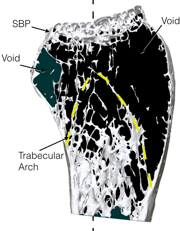
A sagittal section through the scaphoid facet of the distal radius showing the relationship between the subchondral bone plate, trabecular arches, and voids.
Fig. 7.
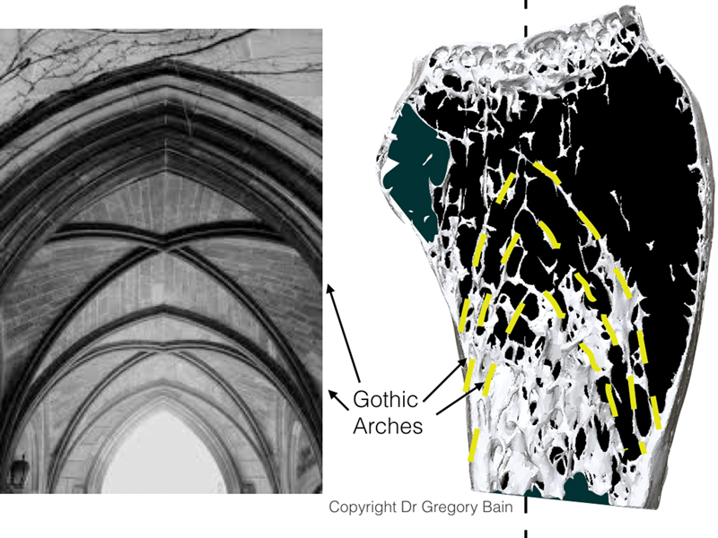
An illustration of a Gothic arch merging to form a Gothic vault. Source: Image received with permission from Dr. Gregory Ian Bain.
Individual Sheets
It is interesting to follow the trabeculae from the SBP to the metaphyseal cortex ( Fig. 8 ). The thin trabecular sheets are perpendicular to the SBP, with a few thin interconnecting trabeculae. The individual sheets fan out just before they coalesce with the endosteal cortex. Each trabecular sheet becomes a ridge on the endosteal cortical surface at the metaphyseal–diaphyseal junction. At the point where the trabeculae coalesce with the cortex, the cortex immediately proximal to it is much thicker.
Fig. 8.
A sagittal section through the distal radius showing the relationship between trabeculae and coalescence to the adjacent cortex.
Cross-sectional images of the metaphysis demonstrate that there are multiple longitudinally endosteal ridges that continue into the diaphyseal region ( Fig. 9 ). Other than the endosteal ridges there is a paucity of trabecular bone within the medullary canal of the diaphysis.
Fig. 9.
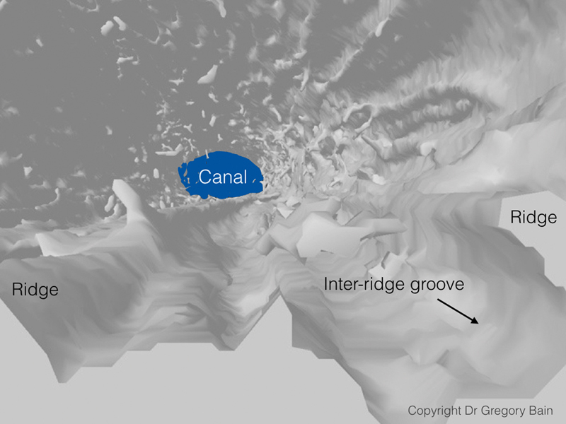
An axial section through the distal radius illustrating grooves and ridges in the cortical bone. Source: Image received with permission from Dr. Gregory Ian Bain.
Cortical Bone
The diaphysis is triangular in cross-section, with the corners on the radiopalmar, ulnopalmar, and dorsal aspects. Using the Hounsfield unit color map, it can be seen that the corners have a thicker cortex than the adjacent flat cortex ( Fig. 10 ).
Fig. 10.
Axial section of the cortical pillars with a radiodensity color scale (Hounsfield units).The relative radiodensity is greater at the dorsal, radiopalmar, and ulnopalmar corners. These are the three pillars of the distal radius.
Discussion
Gross Anatomy
The micro-CT assessment has provided a new insight into the detailed microanatomy of the distal radius, which has allowed a much more thorough interpretation of its structure and function. The SBP, cortex, and medullary bone, all have different morphology and function. We do know that the radius is important for transmitting the considerable load from the carpus to the diaphysis. We also know that it can withstand the forces placed upon it, but is prone to fracture, especially within the osteoporotic patient. So the question is; how does this microanatomy assist the radius in loading? We will review the main points identified, and interpret how it does it.
Subchondral Bone Plate
Statement
The SBP is a unique 2 mm thick multilayer osseous lattice. The primary subchondral bone plate spans the entire width of the distal radius, while the secondary layers are concentrated at the site of maximal carpal loading. At the surface, the voids are spherical, create a sponge, or honeycomb structure. The interlaminar struts being perpendicular to the primary SBP, create multiple mini “I” beams that span between each lamina. Engineers refer to this honeycomb structure with panels on both sides as a sandwich panel. 11 However, in this case, the SBP is a multilayered sandwich panel, especially where the deeper layers support the load-bearing carpus ( Fig. 11 ). The short interlaminar struts reinforce the construct and make it relatively stiff, enabling it to absorb shock loading, resist buckling, and transmit the load from the primary subchondral plate to the deeper layers and beyond.
Fig. 11.
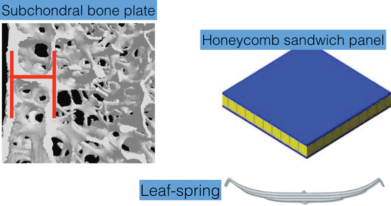
The subchondral bone plate has a unique biological structure with a multilayer osseus lattice. It functions both as a sandwich panel and a leaf spring.
The overall shape of the SBP is that of a leaf spring. When the articular surface is loaded, the primary subchondral plate is compressed, while the deeper layers are in tension. The leaf spring is still used today, especially for suspension on large trucks ( Fig. 11 ).
Medullary Bone
The type of bone proximal to the SBP varies depending upon its position and its loading demands.
The distal cortical metaphyseal rim is continuous with and at the periphery of the SBP. Despite the fact it is extremely thin, it suspends the SBP and provides the ligament attachments for the radiocarpal capsular ligaments. This suggests that the cortical rim is unlikely to be the key factor in transmitting loading to the diaphysis. It becomes progressively thicker toward the diaphysis.
Volar lunate facet has thick straight osseous columns that extend from the site of maximal load-bearing, (volar aspect of the overhanging lunate facet), 12 to the thick volar diaphyseal cortex. The following are colinear; the concentric circles of articulation of the capitate, lunate, and lunate facet, the volar columns and the thick volar cortex.
The metaphyseal arches are composed of fine, delicate trabecular bone which is strategically placed. The apex of the arch is beneath the maximal load-bearing area of the SBP. There are multiple arches, which are in series and are linked with small interarch struts. It is a Gothic arch, which is parabolic in shape, which is known to transfer the load in a longitudinal and laterally direction, to the bases of the arch, without creating tension in any part of the arch. 11 As this trabecular bone is very thin, it will be more flexible, to assist in load-bearing, but is, unfortunately, prone to fracture.
The bases of the trabecular arch are the endosteal ridges, which coalesce with the cortex, which is buttressed by the increasingly thickened metaphyseal–diaphyseal cortex. As each new ridge coalesces with the cortex, the cortex becomes progressively thicker, until it reaches the triangular-shaped diaphyseal cortex. This is a solid foundation on which the thin trabeculae arches.
Intermediate trabeculae span from the SBP to the metaphyseal arches. They enable the load from the SBP to be distributed to the arches, but not specifically to the apex of the arch. When the wrist is loaded in different degrees of motion, the site, and direction of loading changes. The intermediate trabeculae are peripheral to the center of loading and pass to the sides of the arches. Therefore, they increase the area of stable loading on the SBP and the effective width of the arch.
Cortex
The trabeculae of the metaphysis are arranged principally as plates, and where these plates are joined, there are considerable thickenings, which are rod-shaped ( Fig. 4 ). These rods extend proximally and become the ridges on the endosteal surface of the metaphyseal and diaphyseal radius. They are also oriented longitudinally, which would allow them to transmit the articular load and also help reinforce the radius and protect it against torsion and buckling. 13 14 15 We liken the longitudinal rods and plates seen as those seen in an aircraft's fuselage, which contains longitudinal reinforcements called stringers or longerons ( Fig. 12 ). Osteons in the radius are known to align longitudinally in the principal loading direction of the bone. 16
Fig. 12.
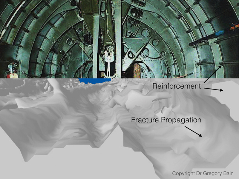
Illustration of an aircraft's fuselage demonstrating longeerons and comparison with the microarchitecture of the distal radius. Source: Image received with permission from Dr. Gregory Ian Bain.
Overview of Modes of Loading: The Arch Bridge
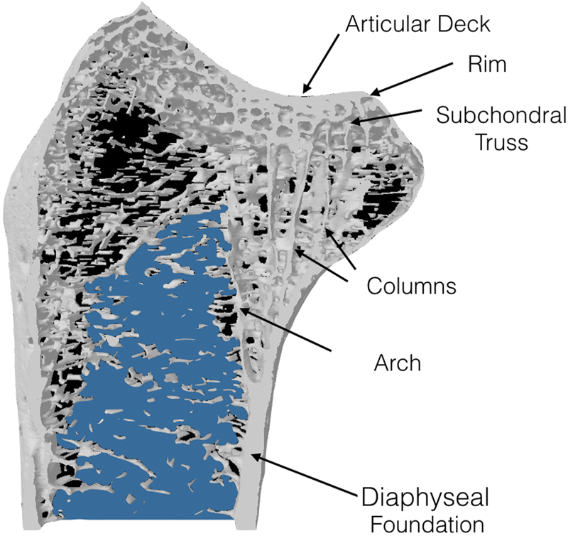
The microstructure of the distal radius metaphysis resembles a bridge, an arch bridge ( Fig. 13 ). The following structures are equivalent; deck–SBP, intermediate struts–intermediate trabeculae, arches–arches, and bridge foundation–cortex.
Fig. 13.
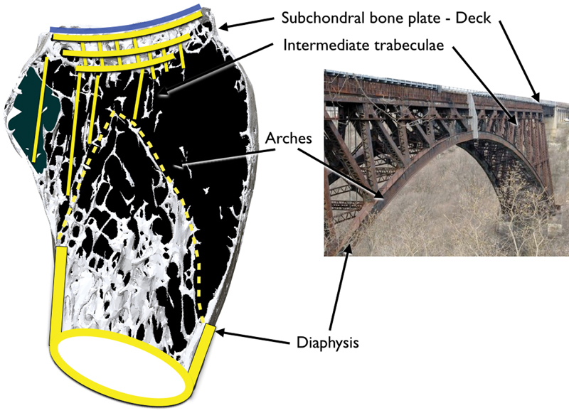
A sagittal view of the distal radius through the scaphoid facet. The distal radius comprises a thin metaphyseal cortex and a thicker diaphyseal cortex. The metaphyseal region contains a concentration of cancellous bone arranged in a series of arches and is called the trabecular vault. The physeal scar abuts the apex of the trabecular vault. There is a subchondral bone plate underlying the articular surface, and this structure is called the subchondral multilaminar plate. The architectural structure resembles that of a bridge.
Articular deck: The bridge deck has the same properties as the SBP. It is a tightly held lattice, with multiple “I” beams in a multilayer sandwich panel construct. The mobile load rolls over the top of the lattice. The lattice is flat, resists buckling, absorbs impact, and takes the entire load.
Any load from the deck will be supported at the rim on each side, the arch, and its adjacent intermediate struts. The arches and the intermediate struts are a delicate semiflexible load-sharing construct, which elegantly distributes the compressive forces from the deck to the base (diaphysis). 17 The shape and orientation of the (micro) architecture ensure that during physiological load, that the construct is principally in compression and that tensile forces are negligible. This is a key point as bone is weak in tension but strong in compression. The shape of the arch is a Gothic or catenary arch, which distributes load more efficiently than other arch formations (e.g., domed or Roman arch). 11 17
Over the lunate facet, which is the main load-bearing aspect of the wrist, the demands are much higher. Here, there are thick columns, which transmit the considerable load straight to the volar cortex of the radius.
As the SBP and the arches absorb the impact and load, they also protect the delicate articular cartilage. If the cancellous bone were exchanged for solid cortical bone with a higher Young's modulus, then its ability to absorb impact would be significantly reduced, and the risk of osteoarthritis could increase.
Modes of Failure: Fractures
The distal radius is well adapted to accommodate everyday physiologic loads. However, even minor falls can cause a fracture of an osteoporotic radius, that is fragile in tension. 18 When falling onto the outstretched hand, the wrist is forced into extension and the proximal carpal row impacts on the dorsal articular surface of the distal radius. The thin metaphysis fractures due to a combination of bending and axial compressive forces. It is the collapse of the metaphyseal bone including the trabecular arches, which leads to the dorsal tilt of the distal radius and loss of radial height. A closed reduction will often fail, as the arches are fragmented, and will not function normally until the bone has united.
Mandziak et al analyzed the CT scans of 100 intra-articular distal radius fractures and observed that the majority of fractures propagated through the flat surfaces and avoided the thickened corner areas. 8 The site of the fractures is not directly related to the cortical thickness. The site of common fractures is in fact on the thicker bone. The corners of distal radius have thin bone. However the fractures rarely occur there. These corners are reinforced with trabecular braces, which protect them against fracture ( Fig. 4 ). Also, the wrist ligaments span across these corners and protect against fractures with the phenomenon known as uncracked-ligament bridging. 19
The Barton fracture dislocation is a splitting of the SBP, which propagates between the volar columns to the maximal curvature of the volar radius. As this is the major load-bearing aspect of the joint, this fracture will have a devastating effect on the function of the joint. Fortunately, a simple volar buttress plate can restore the function.
Limitations
There are limitations of this study, as we have only analyzed the microstructure of the dry distal radius. We have not assessed the contribution of the periosteum, ligaments, and the other soft tissues to distal radius microarchitecture and function.
Ultrastructure versus Microstructure
Previous articles have examined the distal radius ultrastructure in relation to bone density. 20 21 22 23 We have described the microstructure of bone and related this to common mechanical principles. The distal radius is composed of several distinct osseous components, which contribute to the vital function of distributing the load from the hand to the upper limb. An interesting thought is that nature has developed many of these methods, which are now the principles that underpin architecture and engineering.
Conclusion
A better understanding of the inherent mechanical properties provided by the microtrabecular architecture of the bone is likely to be valuable. An appreciation of its contribution to resist impact, transmit load, and its mode of failure could transmit into a better interpretation of fractures and their management.
The microanatomical structure that we have identified has evolved through generations of many species over millions of years. As an engineer once said to us, we know we are getting the architecture right when it resembles nature.
Acknowledgment
The authors thank Egon Perilli, Matthew Masterson, Angus Keogh, Adam Durrant, and Stephanie Low for previous work on distal radius ligament insertion points and data collection.
Footnotes
Conflict of Interest None.
Erratum: Figs. 7 , 9 , and 12 have been corrected as per Erratum published on June 16, 2017. DOI of the Erratum is 10.1055/s-0037-1603805 .
References
- 1.Marble H C. Baltimore, MD: Williams & Wilkins; 1966. History of hand surgery; pp. 1–10. [Google Scholar]
- 2.Chappard C. Microarchitecture assessment of human trabecular bone: description of methods [in French] 2012;28(12):1111–1115. doi: 10.1051/medsci/20122812022. [DOI] [PubMed] [Google Scholar]
- 3.Singh M, Nagrath A R, Maini P S. Changes in trabecular pattern of the upper end of the femur as an index of osteoporosis. J Bone Joint Surg Am. 1970;52(03):457–467. [PubMed] [Google Scholar]
- 4.Currey J. Princeton, NJ: Princeton University Press; 2002. Bones: Structure and Mechanics. [Google Scholar]
- 5.Currey J D. Bone architecture and fracture. Curr Osteoporos Rep. 2005;3(02):52–56. doi: 10.1007/s11914-005-0004-z. [DOI] [PubMed] [Google Scholar]
- 6.Currey J D. How well are bones designed to resist fracture? J Bone Miner Res. 2003;18(04):591–598. doi: 10.1359/jbmr.2003.18.4.591. [DOI] [PubMed] [Google Scholar]
- 7.Melone C P., Jr Distal radius fractures: patterns of articular fragmentation. Orthop Clin North Am. 1993;24(02):239–253. [PubMed] [Google Scholar]
- 8.Mandziak D G, Watts A C, Bain G I. Ligament contribution to patterns of articular fractures of the distal radius. J Hand Surg Am. 2011;36(10):1621–1625. doi: 10.1016/j.jhsa.2011.07.014. [DOI] [PubMed] [Google Scholar]
- 9.Bain G I, Alexander J J, Eng K, Durrant A, Zumstein M A. Ligament origins are preserved in distal radial intraarticular two-part fractures: a computed tomography-based study. J Wrist Surg. 2013;2(03):255–262. doi: 10.1055/s-0033-1355440. [DOI] [PMC free article] [PubMed] [Google Scholar]
- 10.Zumstein M A, Hasan A P, McGuire D T, Eng K, Bain G I. Distal radius attachments of the radiocarpal ligaments: an anatomical study. J Wrist Surg. 2013;2(04):346–350. doi: 10.1055/s-0033-1358614. [DOI] [PMC free article] [PubMed] [Google Scholar]
- 11.Francis A. Oxford, United Kingdom: Pergamon Press; 1980. Introducing Structures: A Textbook for Students of Civil and Structural Engineering, Building, and Architecture. [Google Scholar]
- 12.Andermahr J, Lozano-Calderon S, Trafton T, Crisco J J, Ring D. The volar extension of the lunate facet of the distal radius: a quantitative anatomic study. J Hand Surg Am. 2006;31(06):892–895. doi: 10.1016/j.jhsa.2006.03.010. [DOI] [PubMed] [Google Scholar]
- 13.Kinney J H, Ladd A J. The relationship between three-dimensional connectivity and the elastic properties of trabecular bone. J Bone Miner Res. 1998;13(05):839–845. doi: 10.1359/jbmr.1998.13.5.839. [DOI] [PubMed] [Google Scholar]
- 14.Troy K L, Grabiner M D. Off-axis loads cause failure of the distal radius at lower magnitudes than axial loads: a finite element analysis. J Biomech. 2007;40(08):1670–1675. doi: 10.1016/j.jbiomech.2007.01.018. [DOI] [PMC free article] [PubMed] [Google Scholar]
- 15.Ural A. Prediction of Colles' fracture load in human radius using cohesive finite element modeling. J Biomech. 2009;42(01):22–28. doi: 10.1016/j.jbiomech.2008.10.011. [DOI] [PubMed] [Google Scholar]
- 16.Nalla R K, Stölken J S, Kinney J H, Ritchie R O. Fracture in human cortical bone: local fracture criteria and toughening mechanisms. J Biomech. 2005;38(07):1517–1525. doi: 10.1016/j.jbiomech.2004.07.010. [DOI] [PubMed] [Google Scholar]
- 17.Roth L. Boulder, CO: Westview Press; 2007. Understanding Architecture: Its Elements, History, and Meaning. [Google Scholar]
- 18.Lewis R. Colles fracture-causative mechanism. Surgery. 1950;27(03):427–436. [Google Scholar]
- 19.Nalla R K, Kinney J H, Ritchie R O. Mechanistic fracture criteria for the failure of human cortical bone. Nat Mater. 2003;2(03):164–168. doi: 10.1038/nmat832. [DOI] [PubMed] [Google Scholar]
- 20.Bala Y, Bui Q M, Wang X-F et al. Trabecular and cortical microstructure and fragility of the distal radius in women. J Bone Miner Res. 2015;30(04):621–629. doi: 10.1002/jbmr.2388. [DOI] [PubMed] [Google Scholar]
- 21.Nilsson M, Ohlsson C, Sundh D, Mellström D, Lorentzon M. Association of physical activity with trabecular microstructure and cortical bone at distal tibia and radius in young adult men. J Clin Endocrinol Metab. 2010;95(06):2917–2926. doi: 10.1210/jc.2009-2258. [DOI] [PubMed] [Google Scholar]
- 22.Greenspan S L, Perera S, Recker R et al. Changes in trabecular microarchitecture in postmenopausal women on bisphosphonate therapy. Bone. 2010;46(04):1006–1010. doi: 10.1016/j.bone.2009.12.025. [DOI] [PMC free article] [PubMed] [Google Scholar]
- 23.Lochmüller E-M, Kristin J, Matsuura M et al. Measurement of trabecular bone microstructure does not improve prediction of mechanical failure loads at the distal radius compared with bone mass alone. Calcif Tissue Int. 2008;83(04):293–299. doi: 10.1007/s00223-008-9172-z. [DOI] [PubMed] [Google Scholar]