Abstract
This study investigates the validity of monitoring nose movement, using an infrared stereoscopic camera system (HDMM), to evaluate intracranial movement during treatment with the Icon™-model Gamma Knife®.
Methods
The HDMM was validated by comparison against known displacements. Next, an anthropomorphic phantom was rotated to register nose displacements on the HDMM, which were compared to the displacements of seven intracranial locations determined by cone-beam CT (CBCT). Similarly, CBCT-calculated intracranial displacements were compared against HDMM-reported nose displacements for patients.
Results
HDMM-indicated displacements were accurate within 0.06mm mean. In the phantom, CBCT-calculated nose displacements agreed within 0.05mm (mean) of HDMM-reported nose displacements. In 16 instances intracranial displacements exceeded nose displacements; at the most extreme by 73% (2.76mm versus 1.59mm). Overall, intracranial anatomy displaced by 43% (mean) less than the nose. Patient data included no intracranial target displacements exceeding nose displacements.
Conclusions
Intracranial phantom and patient anatomy displaced by approximately half that of the nose, suggesting nose movement is generally a suitable surrogate for intracranial movement. The study constitutes the presentation of a simple, robust method that can be applied to determine the relationship between nose tip and intracranial motion in real patients undergoing frameless treatments on Icon™.
Keywords: Gamma Knife, mask, Icon, frameless stereotactic radiosurgery, intrafraction motion, stereoscopic nose tracking, cone beam CT
Introduction
Conventional Gamma Knife® (GK) radiosurgery (SRS) relies upon the use of a stereotactic head frame fixated onto the skull. This frame serves three functions. Firstly, in conjunction with a fiducial marker box attached to the frame during imaging, it defines the stereotactic coordinate system with respect to which the locations of the planned radiation isocentres (so-called ‘shots’) are specified. These fiducial markers allow the treatment planning system [Leksell GammaPlan (Elekta AB, Stockholm, Sweden)] to impose onto the planning images this same stereotactic coordinate system. Shots located within the stereotactically-defined image study can then be delivered to the corresponding location in the head by the GK unit itself, which shares the same coordinate system through a high-precision stereotactic couch. The second function of the frame is to rigidly fixate the head allowing reproducible setup at the start of treatment. The third function, also a consequence of rigid fixation, is to securely immobilise the head during radiation delivery, so ensuring geometric accuracy throughout.
In 2015 the latest model of GK – Gamma Knife® Icon™ (Elekta AB, Stockholm, Sweden) – was released. The salient feature of this new model is a novel cone beam CT (CBCT) system. Being integral with and calibrated to the GK unit itself, the images it produces are inherently stereotactic. Consequently, planning images (CT or MRI) rigidly and automatically co-registered against the CBCT within the planning system via mutual information are stereotactically-defined without the need for fiducial markers attached to a head frame. Furthermore, CBCT imaging at the start of treatment is used to verify patient setup. With two of the frame’s functions fulfilled by the CBCT system, frameless GK therapy becomes an option, so providing a solution for fractionated delivery and offering greater flexibility in workflow options.. However, the frame’s remaining function – rigid immobilisation to eliminate intrafraction motion during treatment delivery – cannot be addressed by CBCT.
To address intrafraction motion, Icon™ also includes an infrared stereoscopic camera to continuously monitor the patient during irradiation. This stereoscopic system, known as the high-definition motion management (HDMM) system, monitors the position of a reflective marker placed on the tip of the patient’s nose, relative to four immobile reflectors fixed to the GK head support system [figures 1 and 3(a)]. If the HDMM system detects movement beyond a predefined threshold, irradiation is automatically interrupted.
Implicit in the use of the HDMM system is the assumption that the movement of the nose is an appropriate surrogate for movement of intracranial targets and critical structures. Ideally, the intracranial anatomy would move by an amount equal to or less than the nose tip movement. If this ideal is met, then the HDMM threshold can simply be set at a level corresponding to the maximum target movement deemed acceptable. Under the assumption that the head is a rigid body, translations of the nose tip will indeed correspond to intracranial translations of equal magnitude. However, under rotation the relation between nose tip movement and intracranial movement is less certain. In the hypothetical situation that the point of rotation is centred exactly on the nose tip, intracranial anatomy could undergo large rotational displacement without any corresponding movement of the nose tip at all. While such a scenario is implausible in a clinical setting, it serves to highlight the potential pitfalls in the use of the HDMM system. With these concerns in mind, the aim of this work was to investigate the validity of using nose tip movement as a surrogate for intracranial movement, with particular emphasis on rotations.
Although primarily based upon measurements in an anthropomorphic head phantom, the study also constitutes the presentation of a simple, robust method that can be applied to determine the relationship between nose tip and intracranial motion in real patients undergoing frameless treatments on Icon™. Patient data will provide crucial evidence to choose suitable HDMM threshold levels in the newly-emerging field of frameless Gamma Knife® therapy. Preliminary results from a small number of our early Icon™ patients are included to exemplify the suitability of the presented method to a clinical setting.
Background
Icon™ frameless therapy utilises a patient-specific head cushion and thermoplastic mask. The mask has a cut out through which the nose protrudes to allow it to be monitored by the HDMM. Following manufacture of the cushion and mask in the supine position, the patient undergoes an initial CBCT scan that serves as the stereotactic reference. To this reference scan, CBCTSTXref, a planning-quality tomographic image study (CT or MRI, acquired either with or without mask fixation, and either before or after CBCTSTXref) is rigidly co-registered. From the resulting stereotactically-defined planning study a treatment plan is created following standard procedures. The result is a set of planned shots, each specified by their stereotactic coordinates, Splanned.
Prior to radiation delivery the patient is set up on GK with his/her cushion and mask, a reflective marker attached to his/her nose, and a new CBCT acquired. Acquisition of this setup CBCT (CBCTsetup) zeros the HDMM system, which now continuously monitors any deviation of the patient away from this position. The zero point is set from the HDMM data averaged over the duration of the scan (29 seconds).
Figure 1.
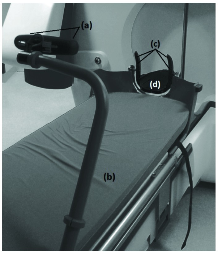
HDMM system, consisting of stereoscopic infrared camera (a) attached to the foot of the couch (b), with a line-of-sight to four immobile reflective markers (c) integral to the Icon™ head support (d)
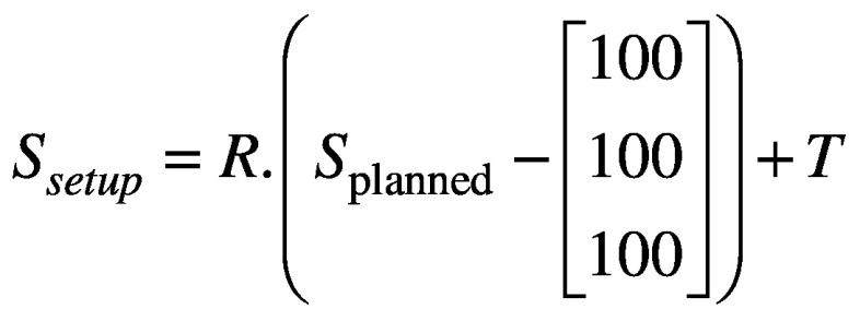
Next, CBCTsetup is rigidly co-registered back to the initial CBCTSTXref and the resulting co-registration translations (Δx, Δy, Δz) and rotations (θx, θy, θz) – where axes x, y and z correspond to the left-right, anterior-posterior and superior-inferior directions, respectively – are reported. These same rotations [applied about stereotactic coordinate (100,100,100)mm in the order: rotation about x, rotation about y, rotation about z] and translations are used to automatically update the planned shot coordinates, so maintaining their location with respect to the anatomy. With the shot coordinates being corrected for the specific setup, the planned dosimetry to the target is maintained. The resulting corrected shot coordinates, Ssetup, are given by:
(1).
where translation matrix 
and rotation matrix 
with 
During delivery of these setup-corrected shots, the HDMM system will interrupt the treatment if the patient’s nose tip deviates from its setup position beyond a user-defined threshold. Treatment will resume when the magnitude of the nose tip displacement returns below threshold; should the displacement not return below threshold, a repeat setup CBCT is acquired and co-registered to CBCTSTXref, resulting in a new set of corrected shot coordinates for delivery and a scan-averaged re-zeroing of the HDMM system.
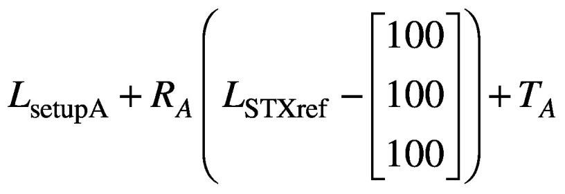
The above workflow depicted in Figure 2 is integral to frameless treatments with the Icon™ system, but the reported co-registration translations and rotations also allow the user to gain insight into nose movements, which can be related to the HDMM data itself. By identifying in Leksell GammaPlan (LGP) the location of the nose tip in the stereotactically-defined planning study, its reference stereotactic coordinates NSTXref can be determined. Assuming some setup ‘A’, the stereotactic coordinates of the nose tip in setup A, NsetupA, are simply determined, in analogy with equation (1), from:
Figure 2.
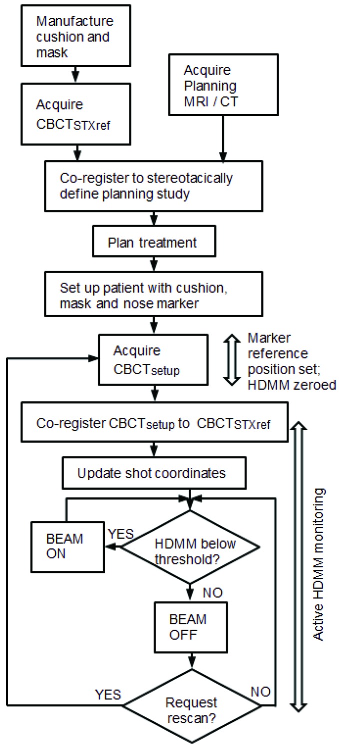
Typical workflow on Gamma knife® Icon™, indicating timings of CBCT scans and HDMM active monitoring within the treatment process.
(2).
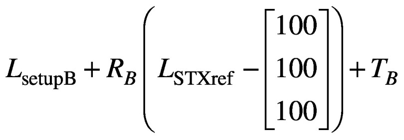
where RA and TA are the rotation and translation matrices derived from the co-registration of CBCTsetupA to CBCTSTXref. Similarly, if the setup then moves from ‘A’ to ‘B’, the new coordinates of the nose tip in setup ‘B’ are given by
(3).
with RB and TB the rotation and translation matrices similarly derived from the co-registration of CBCTsetupB to CBCTSTXref. But in moving from setup ‘A’ to setup ‘B’ the magnitude of the nose displacement is measured by the HDMM system, and this magnitude displacement, Dnose, should simply correspond to:
(4).
The consequence of the above is that the magnitude of nose tip displacements indicated by the HDMM system can be compared against the magnitude of nose tip displacements alternatively derived from calculations based upon the co-registrations of the appropriate CBCT scans. Once it is recognised that the displacement of a stereotactic point corresponding to the nose tip can be related to the HDMM data, it is clear that the same approach can be used for any arbitrary point in stereotactic space, including one representative of an intracranial structure. If the stereotactic coordinates at the centre of some intracranial lesion identified in the planning study are LSTXref, then in analogy with equations 2, 3 and 4 the stereotactic coordinates of the lesion centre in setups ‘A’ and ‘B’ will be given, respectively, by:
(5).
and
(6).
and the magnitude displacement between the two setups subsequently given by
(7).
Equations 5, 6 and 7 provide a means to determine the displacement of an intracranial lesion from the CBCT scans without actually having to visualise that lesion in the CBCT images. Lesion visualisation using Icon™ CBCT is typically impossible due to insufficient soft tissue contrast. Once determined, the displacement of the lesion can be compared against the corresponding nose tip displacement indicated by the HDMM system.
MATERIALS AND METHODS
All results were acquired using GK Icon™ running control system software version 11.0 and Leksell GammaPlan (LGP) version 11.0.1.
Validation of HDMM accuracy
The accuracy of displacements indicated by the HDMM system was investigated using a tool consisting of a weighted base with a mobile point that could be translated in three orthogonal directions, independently. A translation in any one direction is applied by the turning of a thumb wheel. An integral digital display indicates the resulting displacement to 0.1mm. This tool was placed on a thin rubber non-slip surface on a level platform securely attached to the IconTM head support. The tool was oriented with its mobile point facing the HDMM camera and its axes of translations aligned parallel with the x, y, and z axes of the GK unit itself (annotated in Figure 3a). A reflective nose marker was attached to the tool, positioned within the field of the four fixed reflectors, and a series of displacements introduced. The magnitudes of the displacements indicated by the tool were compared to those indicated by the HDMM system. It is stressed that the HDMM system indicates only the magnitude of displacements, not the individual directional components of displacement. Displacements up to a nominal maximum of 2mm were made in the three directions independently, plus composite displacements consisting of combined translations in all three directions.
Figure 3.
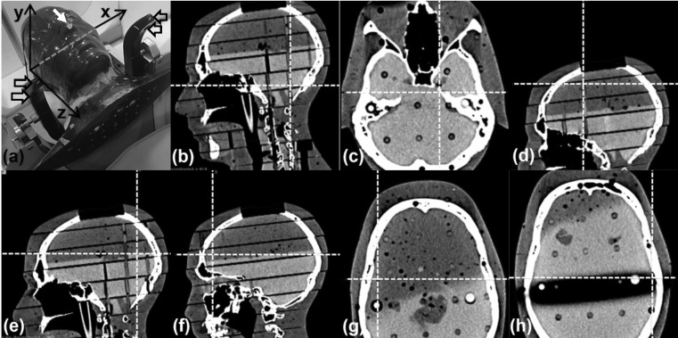
(a) RANDO phantom setup on Icon™ with nose marker (white arrow), immobile reflective markers (hollow arrows) and stereotactic axes indicated. (b) Cerebellar point (99.6, 66.3, 106.0)mm. (c) Left trigeminal nerve root point (117.3, 106.1, 100.7)mm. (d) Superior point (92.3, 120.6, 21.4)mm. (e) Posterior point (98.9, 51.9, 50.4)mm. (f) Anterior point (85.1, 172.2, 59.5)mm. (g) Right lateral point (53.3, 118.6, 58.0)mm. (h) Left lateral point (156.0, 102.0, 64.0)mm.
Anthropomorphic head phantom study
The head of a RANDO phantom (The Phantom Laboratory, New York, USA), consisting of a natural human skull cast inside tissue-simulating plastic, was used in this study. A head cushion was made for the phantom following our standard clinical practice and a CT scan (Siemens Somatom Sensation) of the phantom acquired.
The phantom and cushion were then placed on the Icon™ head support, a reflective marker attached to its nose, and the reference CBCT (CBCTSTXref) acquired. The CT scan was co-registered to CBCTSTXref in LGP, which requires that the rigid co-registration is performed automatically to eliminate inter-observer variability. The automatic co-registration of LGP utilises a simulated annealing numerical optimiser to maximise the similarity metric of a normalised mutual information algorithm1. Within LGP the reference stereotactic coordinates of a point on the nose tip were determined, along with the reference stereotactic coordinates of seven intracranial points. These points consisted of one central point at a location representative of root of the left trigeminal nerve one inferior point near the midline of the cerebellar region and five further points in extreme superior, anterior, posterior, left lateral and right lateral locations (Figure 3).
The phantom and head cushion were then repositioned prior to acquisition of the initial setup CBCT scan (CBCTsetupA). CBCTsetupA was then automatically co-registered to CBCTSTXref in LGP and the resulting translations and rotations recorded. Acquisition of CBCTsetupA also zeroed the HDMM system. The phantom was then moved by a small amount to register a displacement on the HDMM system. After ensuring that the phantom was stable in its new position, as indicated by stability in the HDMM output, the HDMM displacement was recorded. A new setup CBCT (CBCTsetupB) was then acquired, automatically co-registered to CBCTSTXref in LGP and the resulting co-registration translation and rotation recorded. For each of the seven intracranial locations, the magnitude of the displacement between the two setups was then calculated from equation 7. Similarly, the magnitude of the displacement of the nose point was calculated from equation 4. The recorded value (magnitude displacement) of the HDMM was compared against the calculated magnitude displacements of the nose point and the seven intracranial locations.
This process was repeated for a series of HDMM-indicated displacements up to a nominal maximum of 2mm. These displacements were made manually by rotating the phantom about the x’, y’ and z’ axes. Since it was neither trivial, nor particularly desirable, to try to achieve a known fixed origin for these axes of rotation, it is stressed that these x’, y’ and z’ axes of rotation have an arbitrary and undetermined point of origin, and merely lie in directions corresponding to the x, y, z axis convention used by the Gamma Knife® and the co-registration process itself. Each mode of rotation was investigated in turn, covering the nominal 2mm HDMM range in steps of approximately 0.25mm. Using the head cushion and manually-introduced rotations, it was not possible to ensure the intended rotations were introduced in isolation, from neither translations nor other modes of rotation; the aim was only to achieve displacements for which the intended mode of rotation represented a major contribution.
Preliminary patient data collection
For patients undergoing frameless GK Icon™ treatments at our centre, cases of HDMM-triggered treatment pauses are addressed in the first instance by a period of observation during which the HDMM reading may return below threshold. In cases when the HDMM reading does not return below threshold a repeat setup CBCT is performed. Immediately prior to, and throughout the duration of, the acquisition of any such repeat CBCT, the HDMM reading was recorded. The midpoint value of the observed range of the HDMM reading was then compared to the magnitude displacement of points representative of the target volume, as calculated from the co-registrations of their initial and repeat CBCT scans (equation 7). The coordinates chosen as representative of a target were those corresponding to the centre of the associated dose calculation matrix in LGP.
RESULTS
Validation of HDMM accuracy
Figure 4 plots the magnitude of the tool-measured reflective marker displacements against the corresponding displacements indicated by the HDMM system. Across all investigated displacements, the mean(95% confidence interval) difference (HDMM minus tool) was 0.06(0.04 to 0.07)mm. The corresponding differences for each mode of displacement (x only, y only, z only and composite) were 0.11(0.08 to 0.14)mm, 0.09(0.05 to 0.11)mm, 0.06(-0.04 to 0.00)mm and 0.03(0.01 to 0.06)mm, respectively.
Anthropomorphic head phantom study
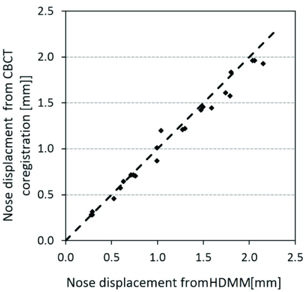
Figure 5 shows the displacements of the nose of the anthropomorphic phantom. Displacements of the reflective nose marker as indicated by the HDMM system are plotted against the displacement of the nose point’s stereotactic coordinate, as calculated from the co-registration of the setup CBCTs against CBCTSTXref. The mean (95% confidence interval) difference between the two methods of nose displacement measurement (HDMM minus calculation) was 0.05(0.01 to 0.09)mm, ranging from 0.16mm to 0.22mm.
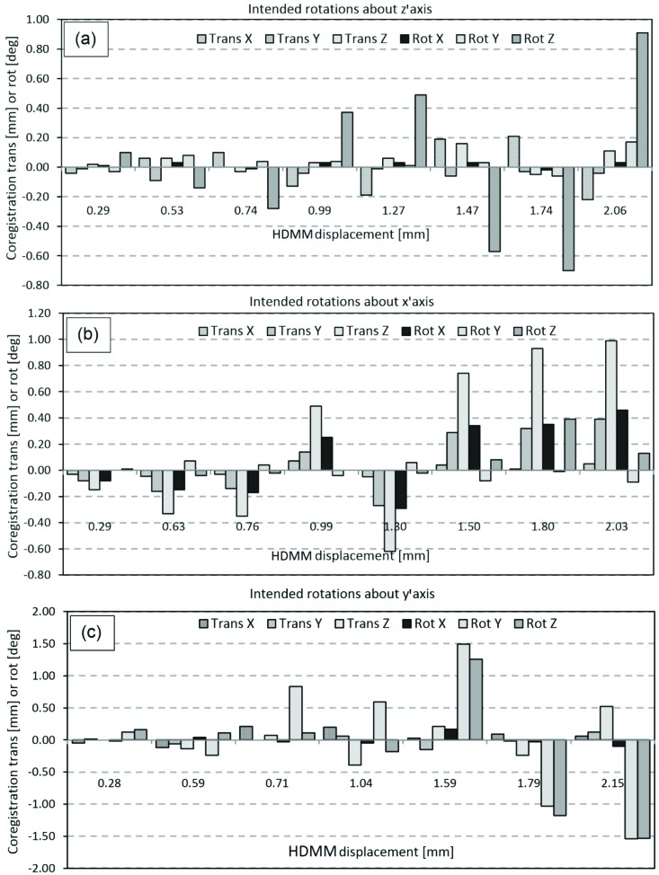
Figure 6 shows the co-registration translations and rotations resulting from each mode of movement applied to the phantom (intended rotations around either the z’ axis, the x’ axis the y’ axis). Figure 6(a) indicates that rotations around the z’ axis were achieved without inducing comparably-sized rotations about the x’ or y’ axes, but that the registration resulting from this mode included relatively large z components of translation. The coregistrations resulting from intended rotations about x’ Figure 6(b) tended to also include substantial components of translation in y and z, whilst Figure 6(c) indicates it was difficult to achieve rotations about y’ without also inducing comparably-sized rotations about z’.
Figure 6.
translation (Trans) and rotation (Rot) co-registration components resulting from the three investigated modes of phantom movement: (a) intended rotation about the z’ axis, (b) intended rotation about the x’ axis, and (c) intended rotation about the y’ axis.
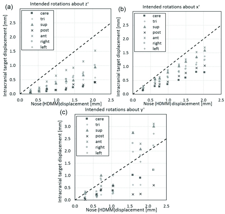
For these three modes of movement, Figure 7 shows the corresponding relation between the magnitude of nose tip displacement and the magnitude of displacement of the seven intracranial locations. In all cases the line of unity is also included; points lying below this line correspond to intracranial locations having been displaced less than the HDMM-indicated nose displacement. Of all 161 investigated movements, 16 resulted in an intracranial location displacing by an amount greater than the displacement indicated by the HDMM. All 16 of these cases corresponded to displacements induced by intended rotations about the y’ axis; Figure 7(c). Including these y’ axis rotation data, the displacements of intracranial locations were, on average, 43(38 to 48)% smaller in magnitude than displacements indicated by the HDMM system [mean(95% confidence interval)]. Discounting the y’ axis rotation data the intracranial locations were displaced by an amount 51(46 to 55)% less than the HDMM-indicated nose displacement on average [mean(95% confidence interval)]. Of the 16 cases for which intracranial displacement was greater in magnitude than nose tip displacement, in the most extreme case the anterior location displaced by an amount 73% greater than the nose tip displacement (2.76mm versus 1.59mm).
Figure 7.
Magnitude of displacement of intracranial anatomy at locations approximately corresponding to the cerebellar midline (cere), left trigeminal nerve root (tri) and extreme superior (sup), posterior (post), anterior (ant), left lateral (left) and right lateral (right), compared against the magnitude of displacement of the nose tip indicated by the HDMM system. Displacements are compared for the three investigated modes of phantom movement: (a) intended rotation about the z’ axis, (b) intended rotation about the x’ axis, and (c) intended rotation about the y’ axis. The line of unity (dotted line) is also included.
Preliminary patient data collection
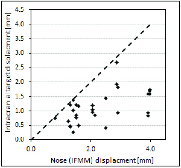
Figure 8 shows the HDMM-indicated nose displacement versus CBCT-calculated magnitude of target displacement for cases where a repeat CBCT scan has been necessary to resume treatment following a pause. These data relate to twelve separate fractions in total, from eleven patients having a combined total of 23 target volumes. Again, the line of unity is included; all points lie below this line corresponding to intracranial targets having displaced by an amount less than the corresponding HDMM-indicated nose tip displacements. Averaged over all these data, the intracranial targets displaced by 46(20 to 72)% less than the HDMM nose displacement.
Discussion
In enabling the use of a mask-based fixation, the Icon™ system increases the flexibility of GK, offering choice of fixation and workflow options with regards to scanning and (pre)planning, but most notably by allowing both conventional single-session and fractionated treatment deliveries. For certain indications fractionation may offer benefits over single-session delivery; examples from CyberKnife- and linear-accelerator-based intracranial therapy include reducing toxicity for larger lesions or those close to critical structures2-4.
An earlier solution for fractionated treatment delivery on Gamma Knife® relied on a bite-block fixation and used a measurement-based reposition check tool to verify setup, with vacuum-monitoring to detect intrafraction motion. While reports have shown sub-millimetre accuracy was achievable with this system, reproducibility of setup relying upon measurement-based verification was not without problems5-7, and these are avoided with the on-board CBCT setup verification offered by Icon™. Nevertheless, the potential for intrafraction motion remains with frameless treatment delivery.
HDMM system accuracy
The use of stereoscopic cameras for a variety of radiotherapy applications has been reported elsewhere, for surface setup of the pelvis on a linear accelerator8, for example, or for monitoring breathing during treatment of tumours in the thoracic region9,10. However, given its relatively recent release, as yet there is no published clinical data relating to Icon™’s commercially-implemented HDMM system. Chung et. al.11 have reported initial results from a prototype system similar in design to the Icon™ HDMM system, but on a linear accelerator with on-board CBCT.
In terms of the magnitude displacement values reported by the HDMM system, our results (Figure 4) indicate an accuracy of the order 0.1mm in all directions. The HDMM system displays displacement to one-hundredth of a millimetre but, even when monitoring a reflective marker on a stationary phantom, the instantaneous value was observed to fluctuate by up to ±0.05mm. Nevertheless, the precision of the HDMM display is smaller than the uncertainty in the readout of the tool against which it was verified (0.1mm) and, within the limitations of the validation test, the HDMM system can be considered accurate. The accuracy of the HDMM system as reported by the manufacturers themselves up to 0.15mm is comparable to that observed here.
Figure 4.
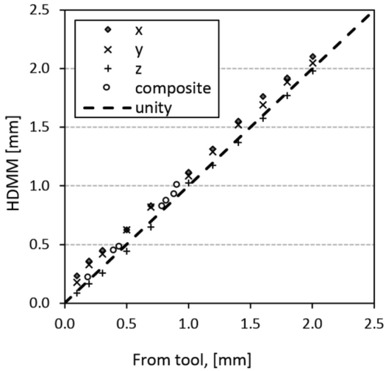
Magnitude of reflective marker displacement as induced by, and measured with, the validation tool, plotted against the corresponding displacement indicated by the HDMM system.
CBCT-CBCT co-registration accuracy
Clearly, validating the accuracy of the HDMM-reported displacement does not constitute a validation of HDMM-monitored nose movement as a suitable surrogate for intracranial motion. However, a validated HDMM system does provide a standard against which the presented method for calculating nose displacement from CBCT co-registration can be benchmarked. The results presented in this study (Figure 5) indicate that the automatic mutual information co-registration by LGP of the images from the Icon™ CBCT system can be reliably used to determine sub-millimetre displacements of the nose tip with sub-millimetre accuracy, typically <0.1mm. And if the co-registration method can be considered to provide sub-millimetre accuracy for a location representative of the nose tip, then it is reasonable to assume equivalent accuracy for displacement of locations representative of intracranial structures also.
Figure 5.
Displacement of the nose marker on the anthropomorphic head phantom as indicated by the HDMM system, plotted against nose point displacement calculated from co-registration of phantom’s CBCT scans. The dashed line represents the line of unity.
It is noted that the Icon™ CBCT system reconstructs a 448×448×448 matrix covering a volume of 224×224×224mm3, giving a 0.5mm voxel size, which is coarser than the accuracy indicated by our data. However, it is stressed that mutual information co-registration algorithms have been shown to be capable of achieving sub-voxel accuracy12, due to the suppression of pixilation error resulting from the large degree of redundancy in the image data typically used for co-registration (in the case of Icon™ 448×448×448, or approximately 90 million, voxels are available), and due to the fact that the transformation isn’t limited to the discrete space of the voxels themselves. Co-registration translations and rotations quoted to a similar degree of precision are reported elsewhere for the IconTM CBCT system13 and although the details are beyond the scope of the current work, repeated automatic co-registration of the same image sets from different starting points within LGP, conducted as part of the commissioning of the Icon™ system at our centre, demonstrated variations in the reported translation and rotations of less than 0.06mm and 0.07°, respectively.
Nose movement versus intracranial movement
Figure 7 shows that in the majority of cases (145 out of 161) the seven intracranial locations displaced by an amount less than the HDMM-indicated nose displacement. Observations of intracranial movement less than nose movement are desirable since, if this relationship can be guaranteed, an appropriate HDMM threshold level can be easily determined; simply set the threshold at a level equivalent to the maximum intracranial displacement that is deemed acceptable and the user can be certain the treatment will be paused before such a displacement is exceeded. What that acceptable level of displacement actually should be goes beyond the scope of the current work, but should likely be considered in the context of other uncertainties inherent in GK treatment delivery, not least the uncertainty in the delineation of the target and critical structures from the planning images. It is stressed that, in conventional frame-fixated GK SRS, geometric accuracy of shot positioning is at the sub-millimetre level.
Of those cases where intracranial displacement exceeded nose point displacement, all resulted from phantom movements where rotation about the y’ axis was a major component [figures 6(c) and 7(c)]. This observation would seem consistent with the point of rotation lying close to the occiput, near the centre of the corresponding depression in the supporting cushion. With such a pivot point, rotations around z’ would cause only small displacements of cerebellar and posterior anatomy, but greater displacement of anterior anatomy, and this pattern of displacement is indeed observed; Figure 7(a). Rotations around x’ would likely lead to a similar pattern of displacement, again, as is observed in Figure 7(b), but rotations around y’ would be notably different; a y’ axis of rotation through the centre of the cushion would likely also intersect a point on the front of the head very close to the nose. In this case, rotations about y’ would lead to relatively small nose tip displacements, particularly in comparison to displacements of extremely superior or extremely lateral intracranial anatomy.
Irrespective of the exact nature of the movements achieved in this study, it is stressed that these data relate to measurements in a phantom. It would have been possible to investigate the relationship between intracranial and nose tip displacement in an entirely theoretical manner, since the movement of two points moving rigidly about a fixed axis is trivial to calculate. However, the measurement-based phantom investigation of this study constitutes the presentation of a method for relating intracranial movement derived from CBCT co-registration to HDMM data that can be applied to real patients, and this was one of the primary objectives of the study. Furthermore, the use of an anthropomorphic phantom at least provides a means by which anatomically relevant points, positioned at clinically plausible locations in stereotactic space, can be selected and subjected to movements at least somewhat representative of a real head. Nevertheless, given our measurements are in a phantom, it would be incorrect to assert that our observations are entirely representative of real patients undergoing natural biomechanical movement in an IconTM mask. However, despite our data being phantom-based, the observation that intracranial anatomy was typically displaced by an amount 43% less than the nose displacement is consistent with the observations of Chung et. al.11 who found, for four patients fixed in a mask, treated on a linear accelerator with on-board CBCT and tracked with a prototype stereoscopic system, that average intracranial target motion from CBCT was 47% less than optically-tracked nose tip movement (0.27mm versus 0.51mm, respectively). Due to the steep dose gradients inherent with GK treatments, more stringent control of intrafraction motion may be appropriate for frameless delivery on the new IconTM system than is necessary for linac-based solutions.
Preliminary data from our own frameless Icon™ patients who have required repeat CBCT indicate intracranial displacements that are smaller than the corresponding nose tip displacements. At this stage, the size of this patient data is still rather small making it difficult to draw any meaningful conclusions, but it is again noted that the magnitude of the intracranial target displacements relative to nose displacements are similar to those reported by Chung et. al.11 and consistent with our own phantom data. Importantly, to have been able to collect these data serves to demonstrate the applicability of the presented method to a true clinical setting too. It is difficult to speculate about the likely pivot points in these clinical cases, since they most likely vary, dependent upon a host of factors specific to each patient and their unique mask-cushion combination. For the phantom it was possible to speculate that the likely pivot point was close to the centre of the occiput depression in the cushion and while this is plausible in a clinical setting also, this point is not the only realistic one. If the patient’s body was fixed absolutely, then the only possible pivot point for the skull on the cervical spine would lie close to the foramen magnum, so more anterior and inferior to a central cushion-based pivot point. The purpose of the cushion and mask is to minimise the potential for patient movement, but their efficacy in this function depends not only on the skill of the operator making the mask and cushion, but also unavoidable patient characteristics. A rounded face, for example, will be less-easily immobilised than will a patient with more angular facial features. At our centre, the mask is typically moulded to fit closely along the jaw line with the patient’s mouth closed, but the mandible itself is mobile with respect to intracranial anatomy. Furthermore, in patients with relatively thick layers of subcutaneous fat around their face, even a well-fitted mask may provide only crude immobilisation under conditions of skin slippage. And given the further possibility of slippage of the cushion’s position inside the head support itself, a mask that is close-fitting around the cut out for the nose could lead to a relatively anteriorly-located pivot point. Of course, any scenario that tends to move the pivot point closer to the nose is detrimental to the suitability of the use of nose movement as a surrogate for intracranial movement.
Future work
Although the observations of this study are primarily based on phantom data, the demonstration that the presented method can be applied in a clinical setting is promising. The continuation of this patient data analysis represents an obvious opportunity for further work. It should be recognised however, that although Icon™ CBCT is optimised for the bony anatomy considered as a rigid body in the cranium, extracranial anatomy in real patient images will be subject to some level of intrafraction deformation and that, as a consequence, co-registration accuracy may be expected to be less than has been achieved in the phantom.
While the amount of data from patients having undergone a re-scan at our centre to date is sparse, data from all our frameless patients (a total of seven, constituting 26 individual fractions) provides some further information on interfraction setup variability that is perhaps indicative of intrafraction rotations our Icon™ mask-fixated patients may be expected to exhibit. For these 26 fractions, average variability in setup co-registration rotation is 1.6°, 1.6° and 2.2° for θx, θy and θz, respectively. So while Figure 8 includes no cases where target displacement has exceeded nose tip displacement, the observation of interfraction θy variability perhaps suggests intrafraction rotations about y’ are likely and so such a relationship may not be maintained as we collect more data. If cases of target displacement exceeding nose displacement are indeed observed, then results from the phantom study suggest it may be appropriate to consider lesion location when deciding upon an appropriate HDMM threshold; a lower threshold may be appropriate for particularly superior or lateral targets, for example. Setting a HDMM threshold involves balancing a desire to maintain the tightest possible geometric accuracy and the need to achieve an efficient treatment that is deliverable without an excessive number of pauses. At our centre, we currently apply a threshold of 1.0mm for the majority of our patients. Evidence indicating that larger tolerances may be acceptable for certain target locations would be useful but, to date, there is no published clinical data to inform choice of appropriate HDMM thresholds for frameless treatment with Gamma Knife® IconTM and on-going collection of such clinical data represents important future work for the Gamma Knife® community.
Figure 8.
Displacement of points representative of the centre of intracranial target volumes, compared against displacements of the nose tip indicated by the HDMM system, from eleven patients undergoing frameless GK Icon™ therapy at our centre. The line of unity (dotted line) is also included.
Conclusions
The Icon™ HDMM system is an accurate, reliable tool for continuously monitoring the displacement of a nose point for patients undergoing frameless GK therapy. The method presented here for relating the displacement of intracranial anatomy to these HDMM-reported nose tip displacements has been proved successful in this phantom study, and preliminary results indicate the method can be equally applied to determine the relation between nose tip and intracranial displacements in real patients undergoing frameless treatments on Icon™. In the majority of cases, intracranial phantom anatomy was found to be displaced by an amount approximately half that of the HDMM-indicated nose displacement, suggesting nose movement is generally an appropriate surrogate for intracranial movement. Cases for which intracranial phantom displacement exceeded nose displacement were associated with movement including a substantial component of rotation about y’, and related to intracranial phantom anatomy in particularly extreme superior, anterior or lateral locations. When deciding upon a suitable HDMM threshold level it may be appropriate to consider target location, but more clinical data from patients undergoing frameless therapy on Icon™ is required to gain further insight. It is the collection of this data that represents the next stage of this study.
Acknowledgements
Authors’ disclosure of potential conflicts of interest
Dr. Wright reports attendance at user group meetings of early Icon adopters and meetings organized and hosted by Elekta. All other authors reported no conflict of interest.
Author contributions
Conception and design: Gavin Wright, Natalie Harrold, Peter Bownes
Data collection: Gavin Wright, Natalie Harrold, Paul Hatfield, Peter Bownes
Data analysis and interpretation: Gavin Wright, Natalie Harrold, Paul Hatfield, Peter Bownes
Manuscript writing: Gavin Wright, Natalie Harrold, Paul Hatfield, Peter Bownes
Final approval of manuscript: Gavin Wright, Natalie Harrold, Paul Hatfield, Peter Bownes
References
- Studholme C., Hill D., Hawkes D.: An overlap invariant entropy measure of 3D medical image alignment. Pattern Recognit. 1999;32(1),71–86 [Google Scholar]
- Minniti G., D’Angelillo R., Scaringi C., et al. : Fractionated stereotactic radiosurgery for patients with brain metastases. J. Neurooncol. 2014;117,295–301 [DOI] [PubMed] [Google Scholar]
- Minniti G., Esposito V., Clarke E., et al. : Fractionated stereotactic radiosurgery for patients with skull base metastases from systemic cancer involving the anterior visual pathway. Radiation Oncology. 2014;9,110-8 [DOI] [PMC free article] [PubMed] [Google Scholar]
- Lischalk J., Oermann E., Collins S., et al. : Five-fraction stereotactic radiosurgery (SRS) for single inoperable high-risk non-small cell lung cancer (NSCLC) brain metastases. Radiation Oncology. 2015;10,216-23 [DOI] [PMC free article] [PubMed] [Google Scholar]
- Ruschin M, Nayebi N, Carlsson P., et al. : Performance of a novel repositioning head frame for Gamma Knife Perfexion and image-guided linac-based intracranial stereotactic radiotherapy. Int. J. Radiation Oncology Biol. Phys. 2010;78(1),306–13 [DOI] [PubMed] [Google Scholar]
- Sayer F., Sherman J., Yen C., Schlesinger D., Kersh R., Sheehan J.: Initial Experience with the eXtend System: A Relocatable Frame System for Multiple-Session Gamma Knife. Radiosurgery, World Neurosurgery. 2011;75(5/6),665-72 [DOI] [PubMed] [Google Scholar]
- Schlesinger D., Xu Z., Taylor F., et al. : Interfraction and intrafraction performance of the Gamma Knife Extend system for patient positioning and immobilization. J Neurosurg (Suppl). 2012;117,217–24 [DOI] [PubMed] [Google Scholar]
- Li W., Sie F., Bootsma G., Moseley D., et al. : Geometric Performance and Efficiency of an Optical Tracking System for Daily Pre-treatment Positioning in Pelvic Radiotherapy Patients. Technology in Cancer Research and Treatment. 2011;10(2),163-70 [DOI] [PubMed] [Google Scholar]
- Stock M., Kontrisova K., Dieckmann K., et al. : Development and application of a real-time monitoring and feedback system for deep inspiration breath hold based on external marker tracking. Med. Phys. 2006;33(8),2868-77 [DOI] [PubMed] [Google Scholar]
- Mittauer K., Deraniyagala R., Li J., et al. : Monitoring ABC-assisted deep inspiration breath hold for left-sided breast radiotherapy with an optical tracking system. Med. Phys. 2015;42(1), 134-43 [DOI] [PubMed] [Google Scholar]
- Chung C., Li W., Bootsma G., Cho Y., et al. : Clinical Evaluation of a Novel Thermoplastic Mask System With Intrafraction Motion Monitoring Using IR. Tracking and Cone Beam CT for Gamma Knife Radiosurgery. Int. J. Radiation Oncology Biol. Phys. (Suppl). 2014;9(1):S848 [Google Scholar]
- Maes F., Collignon A., Vandermeulen D., et al. : (1997), Multi-modality image registration by maximization of mutual information, IEEE Trans. Med. Imag. 1997;16,187-198 [DOI] [PubMed] [Google Scholar]
- Li W., Cho Y., Ansell S., et al. : (2016). The Use of Cone-Beam Computed Tomography for Image-Guided Gamma Knife Stereotactic Radiosurgery: Initial Clinical Evaluation, J. Radiation Oncology Biol. Phys. 2016;96(1), 214-220 [DOI] [PubMed] [Google Scholar]


