Abstract
The ideal stent must fulfil a broad range of technical requirements. Stents must be securely crimped onto the delivery balloon and, in this form, must have a low profile and be sufficiently flexible to facilitate deliverability to the lesion site without distortion or displacement. Following expansion, stents must exert sufficient radial force on the vessel wall to overcome lesion resistance and elastic recoil. To achieve an optimal lumen diameter, the lesion must be uniformly and adequately scaffolded, with minimal tissue prolapse between struts but without compromising side-branch access. Furthermore, the deployed stent must conform to the vessel curvature to minimise vessel distortion, particularly at the stent edges. Radio-opacity is also important to guide safe positioning, adequate deployment and postdilataion and to permit assessment of optimal stent expansion. Equally though, the stent lumen must also be sufficiently visible to allow radiographic assessment of flow dynamics and restenosis. Efforts to optimise one characteristic of stent design may have detrimental effects on another. Thus, currently available stents all reflect a compromise between competing desirable features and have subtle differences in their performance characteristics. Striving to achieve stents with optimal deliverability, conformability and radial strength led to a reduction in longitudinal strength. The importance of this parameter was highlighted by complications occurring in the real-world setting where percutaneous coronary intervention is often undertaken in challenging anatomy. This review focuses on aspects of stent design relevant to longitudinal strength.
Keywords: percutaneous coronary interventions, drug eluting stents, longitudinal deformation, bench testing
Introduction
The last 40 years have witnessed extraordinary technological advances which have seen percutaneous coronary intervention (PCI) evolve into mainstream therapy for revascularisation of coronary artery disease.1 Although there have been many important milestones, the introduction, miniaturisation and evolution of coronary stents have arguably been pivotal to this transformation. The first stent designs were primitive, constructed from thick stainless steel and mounted on crude balloon technology.2 Although they achieved the initial objective to prevent abrupt vessel closure and minimise elastic recoil, deliverability through complex anatomy was challenging and the propensity towards restenosis was high.3
Subsequent evolution of stent design has seen the parallel drive towards improving mechanical properties of stents and balloons to aid device delivery and vessel conformability, in combination with the introduction of technologies to inhibit restenosis. Current generation low profile, highly flexible drug-eluting stents (DES) offer major improvements in clinical outcome and have allowed PCI to be undertaken in extremely complex anatomy.4–6
Stent design
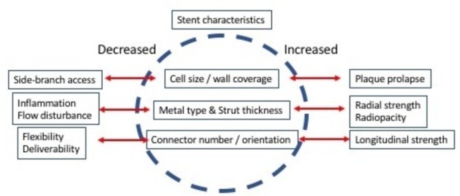
The ideal stent must fulfil a broad range of technical requirements (figure 1). Stents must be securely crimped onto the delivery balloon and, in this form, must have a low profile and be sufficiently flexible to facilitate deliverability to the lesion site without distortion or displacement. Following expansion, stents must exert sufficient radial force on the vessel wall to overcome lesion resistance and elastic recoil. To achieve an optimal lumen diameter, the lesion must be uniformly and adequately scaffolded, with minimal tissue prolapse between struts but without compromising side-branch access. Furthermore, the deployed stent must conform to the vessel curvature to minimise vessel distortion, particularly at the stent edges. Radio-opacity is also important to guide safe positioning, adequate deployment and postdilataion and to permit assessment of optimal stent expansion. Equally though, the stent lumen must also be sufficiently visible to allow radiographic assessment of flow dynamics and restenosis. Efforts to optimise one characteristic of stent design may have detrimental effects on another. Thus, currently available stents all reflect a compromise between competing desirable features and have subtle differences in their performance characteristics.
Figure 1.

Technical requirements of coronary stents. The ideal coronary stent requires compromise in desirable characteristics. Improvement in one aspect of stent performance may have deleterious effects on another.
Radial and longitudinal integrity
Evolution of stent design has tended to focus on aspects in which early stents were considered weak. Predominantly, this has driven improvements in deliverability, conformability, side-branch access and radial strength with rather less attention given to other characteristics such as longitudinal integrity. This latter parameter is defined as the ability of a stent to resist a longitudinal distorting force. As observed with radial strength, longitudinal integrity has an intimate relationship to the strength of stent hoops and the number, design and orientation of connectors between adjacent stent hoops.
Radial strength of the stent hoops is largely determined by three factors: the metal alloy (or polymer), strut thickness and stent architecture. First-generation stents were mostly manufactured from 316 L stainless steel where thickness was a major determinant of strength. More recently, alloys, such as cobalt chrome and platinum chromium, have largely replaced stainless steel for most stent models because they permit reduced strut thickness, while maintaining adequate radial strength and radio-opacity. Thinner struts provide a lower crimped profile and, at least in theory, better stent deliverability. Thinner struts may also reduce disturbance to blood flow, abnormal shear parameters and the the localised inflammation that occurs following stent implantation. This may translate into lower rates of restenosis and improved clinical outcomes.7–9 The reduction in strut thickness achieved over the past 15 years has been remarkable. The first DES, Cypher (Cordis), was essentially a modified bare metal stent and had a strut thickness of 140 µm in addition to the polymer/drug coat. The more contemporary Biomatrix (Biosensensors International) stainless steel stent has a strut thickness of 112 µm. In contrast, use of cobalt chromium has allowed further reductions. For example, the Xience (Abbott Vascular) platform achieves a strut thickness of 81 µm, while recent re-engineering of the Resolute Integrity (Medtronic) platform to incorporate a platinum core (Resolute Onyx) has allowed strut thickness to be reduced from 91 µm to 74 µm, maintaining strength while improving radio-opacity.
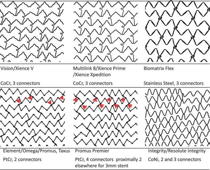
Stent architecture is also critical (figure 2). Stents are either laser cut from a metal tube or may be formed from a wire coil to generate a series of sinusoidal hoops linked by a number of connectors. The number of connectors between hoops has a major impact on stent flexibility, deliverability and conformability. The Cypher stent had six connectors between each hoop, in contrast most contemporary models with only 2–3 connectors. Sinusoidal hoops in turn may be aligned in phase (peak-to-trough) or out of phase (peak-to-peak). In the peak-to-trough design, hoops are usually linked by a direct ‘weld’ to stitch hoops together, while peak-to-peak designs require a connector. These may be straight or angulated relative to the long axis of the stent. Connector alignment between successive hoops also impacts longitudinal integrity as if aligned in a row can create a stiff spine to the stent.
Figure 2.
Design of coronary stents. Depicted are Vision scans of the 3.0 mm diameter examples of six stent designs and listed are the stent names and design characteristics. The Vision and Multi-Link 8 have in-phase sinusoidal hoops linked by three bridges that join peaks and troughs and are aligned with the long axis of the stent. Each connector has a U-shaped loop to increase flexibility. The Biomatrix Flex has out-of-phase sinusoidal hoops with peaks linked by two S-shaped connectors. The Element design has sinusoidal hoops with offset peaks linked by two straight bridges per hoop. The Promus Premier has the same design as the Element except that the proximal three hoops are linked by four connectors, in contrast to two connectors in the Element. The red arrows indicate the connectors. The Integrity design has a single sinusoidal component that winds helically from one end of the stent to the other, with two or three welds between adjacent hoops. CoCr, cobalt chromium; CoNi, cobalt nickel; PtCr, platinum chromium. Reprinted with permission from Ormiston JA et al.24
Longitudinal deformation
Striving to achieve stents with optimal deliverability, conformability and radial strength led to a reduction in longitudinal strength. The importance of this parameter was highlighted by complications occurring in the real-world setting where PCI is often undertaken in challenging anatomy. Cases of longitudinal shortening and elongation were first reported in the mid-1990s with the wire coil Wiktor stent (Medtronic).10 11 These phenomena were associated with adverse clinical sequelae, including the need for immediate coronary artery bypass grafting surgery. In the context of recent generation stents, Pitney et al described 14 cases of major stent deformation with the two-connector Endeavor/Driver (Medtronic) stents. Distortion occurred in 1.8% of the 775 stents that were postdilated.12 When recognised immediately, restenting was required in nine patients with major adverse clinical sequelae in five patients (36%). Subsequently, there have been multiple reports of longitudinal shortening with an approximate procedure occurrence rate of about 0.2%, predominantly occurring with the Promus Element (Boston Scientific) stent and less frequently with other stent models.13 14 The precise incidence is uncertain as reporting bias is likely given that few centres use all stents in equal proportions. Furthermore, longitudinal distortion is likely a spectrum with regard to severity, with more subtle cases easily being missed during fluoroscopic assessment, while enhanced radio-opacity with certain stents may make the phenomenon more apparent.15
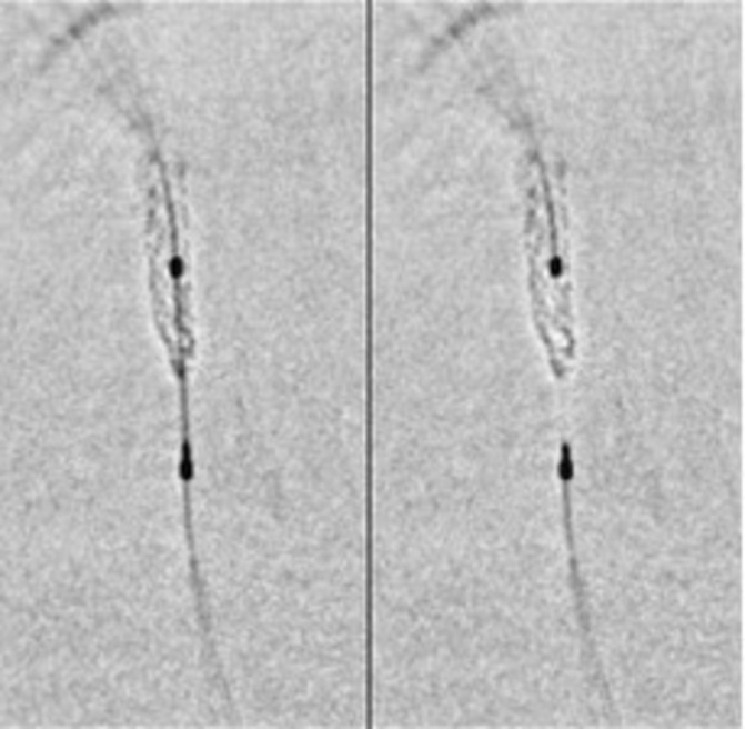
The aetiology of stent deformation is usually advancement or withdrawal of equipment across the deployed stent with a resultant snagging on suboptimally expanded, malapposed struts or failure of equipment to track through the stent in the case of tortuous anatomy. This may include postdilatation balloons, guide catheter extensions or intravascular imaging catheters. A frequently cited additional cause is inadvertent deep throating of the guide catheter on withdrawal of the stent balloon or removal of a buddy wire.16 Aside from longitudinal stent strength predisposing to this phenomenon, deformation is possibly more likely with an open cell as opposed to a closed cell design, at least in carotid interventions.17 The end result is a concertina-like effect of the stent resulting in a characteristic wedding band appearance within a segment, most often at or near the proximal end of the stent (figure 3). As observed with other mechanical complications (eg, stent fracture), longitudinal deformation almost certainly predisposes to stent thrombosis; however, the magnitude of this risk is difficult to ascertain.
Figure 3.

Angiographic evidence of longitudinal deformation. Angiographic evidence of compression of the distal end of a stent placed in the left anterior descending artery following removal of a tightly trapped ‘buddy’ wire. StentViz (GE Healthcare) images illustrating the crumpled distal stent edge.16
Bench testing
The behaviour of stents in clinical practice may vary from assumptions made during the engineering and software modelling phase. Bench testing provides a standardised evaluation of various stent characteristics and allows comparisons to be made between different models. This is important as stents may, for example, behave differently from anticipated in terms of flexibility when crimped on the balloon (which may impact delivery) and conformability once expanded.18 Bench testing can also provide unique insights into more complex procedural techniques such as bifurcation stenting and has helped to highlight the importance of kissing balloon inflation to optimise strut apposition to the vessel wall.19
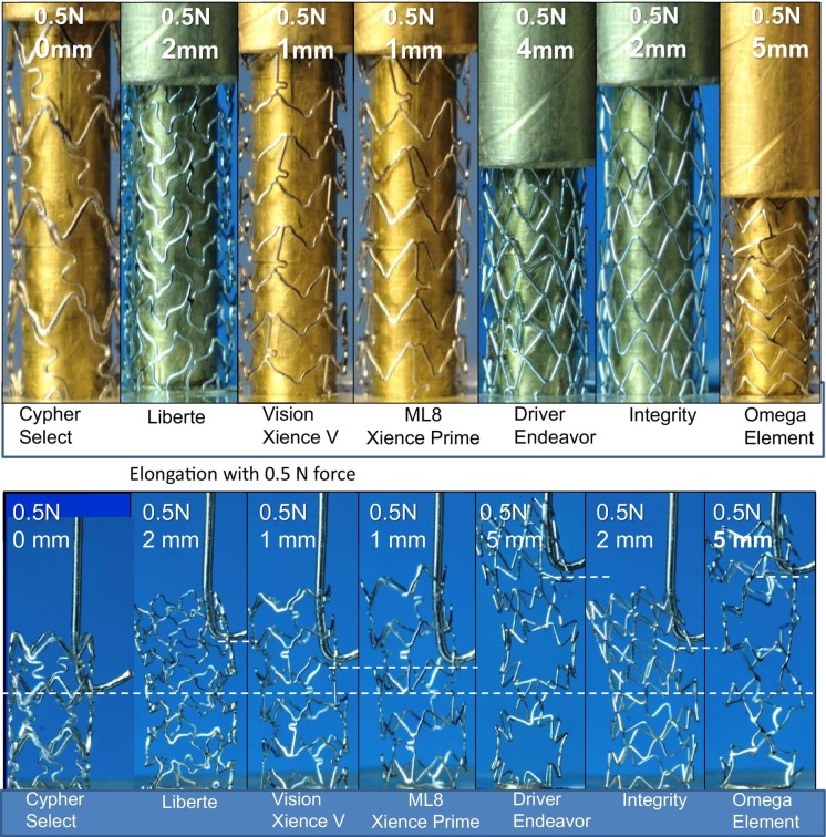
Bench testing has proven invaluable in advancing understanding of the mechanisms involved in longitudinal deformation. One of the first bench tests to assess this involved mounting expanded stents on a mandrel and applying a force of 0.5 N to measure the degree of compression in a 10 mm segment of exposed stent and elongation in an 8 mm segment of exposed stent with 0.5 N force applied using a hook (figure 4).20 21 These tests documented clear differences between devices with Promus Element and Endeavor (Medtronic) models, most prone to compression and elongation. In contrast, Cypher (Cordis), Xience (Abbott Vascular) and Integrity (Medtronic) models were more resistant. Although each of these models have unique designs, the six-connector, thick-strut Cypher stent was the least likely to be distorted, the two-connector Promus Element and Endeavor stents the most likely and the remaining three-connector stents tested somewhere in between. Analysis of distorted stents following this bench test showed that stent ends were frequently distorted in a ‘concertina’ manner, leading to marked compromise of the vessel lumen. Despite excellent resistance to longitudinal distortion, the Cypher stent is no longer widely used, in part because it is less flexible, deliverable and conformable than other stents. Similar findings have been described in other studies, with subsequent work indicating that both the number of connectors and connector orientation (peak-to-peak vs peak-to-trough), which largely determines connector angle, were of major importance at predicting the degree of compression.
Figure 4.
Longitudinal integrity assessed using bench testing (A, upper panel). Stent compression under a fixed load of 0.5 N. The least compressible stent was the six-connector Cypher, and the most easily compressed were the two-connector Promus Element and Driver stents (B, lower panel). Stent elongation testing showed similar, but reciprocal, findings to the compression test results. Reproduced with permission from Ormiston et al.20
Early bench tests were relatively simple and largely applied symmetrical compression across the end of the stent while the stent was mounted and partially supported by a mandrel. More clinically relevant bench tests have been developed to provide more realistic assessment by assessing stents through point loading in 5 mm of exposed stent length. This has been used to demonstrate improved longitudinal integrity of the Promus Premier device (which increased the number of connectors in the proximal hoops) compared with its predecessor, the Promus Element which was noted to have deficiencies in terms of this parameter both in clinical usage and bench tests. In some stent models, the number of connectors varies between hoops. For example, the proximal three hoops of Promus Premier have four connectors and then revert to two connectors thereafter. Bench tests assessing only 5 mm of exposed stent may be less than ideal as the point of compression in clinical practice (particularly when due to snagging of a postdilatation balloon or in bifurcation stenting) may be more distal than this. This has been successfully modelled using 4, 7 and 12 mm exposed stent in a recently published study which confirms that should loading occur with more exposed stent, even the proximal hoop reinforcements included in the redesigned Promus Premier are unable to prevent distortion from occurring.22 Thus, stent deformation continues to be an important consideration in contemporary PCI.
Prevention and management of longitudinal deformation
Where recognised, longitudinal deformation can pose critical challenges to a successful PCI procedure. This is not solely related to enhanced thrombotic risk posed by malapposed struts but also to inherent difficulties in recrossing the deformed stent to permit postdilatation and achieve improved stent expansion. Deformation may result in geographic miss of the lesion and may mandate insertion of an additional stent, potentially leading to multiple layers of metal in the segment where the first stent has been deformed and the second stent overlapped. Consequently, prevention of deformation is key and centres around awareness of three factors: first, knowledge of individual stent architecture and expansion characteristics to guide appropriate stent selection; second, understanding the anatomical scenarios where longitudinal deformation is likely to occur and third, routine application of techniques to avoid inducing deformation.
Stent selection is key. Most deformation is due to equipment catching on the proximal end of a stent and consequently in scenarios where deformation is considered more likely to occur (eg, highly angulated ostial circumflex lesion), it would be prudent to select stents with greater proven strength in the proximal segment. Equally, in the majority of instances, longitudinal deformation is a result of interventional equipment catching on struts that are separated from the vessel wall. These malapposed struts are more likely to occur in tapered vessels where there is marked size mismatch between proximal and distal portion of the diseased segment, especially when the stent is ‘sized’ according to the smaller reference diameter with intention to upsize the larger segment during postdilatation.23 Deployment pressure is also an important factor—an oversized stent deployed at low pressure is more likely to have more malapposed struts than an appropriately sized stent deployed at high pressure. This can occur due to failure to fully expand the stent, but also from the balloon adhering to stent struts while it unwraps.
Postdilatation balloons are the most common device used to recross a deployed stent and should be advanced slowly and gently under fluoroscopic imaging. Stents deployed around a tight bend may also be at increased risk of deformation because wire bias directs the nose of balloons or other devices against the edge of the stent, causing the devices to become stuck against struts. This may be more likely when treating bifurcation lesions as there is often a size mismatch from proximal to distal vessel which leads to initial underdeployment of the proximal end of the stent. Proximal optimisation is therefore essential and should be done as early as possible to ensure complete apposition.
Distortion is also often due to damage from the guide catheter. This is more likely where the stent has been deployed in an ostial or very proximal position and withdrawal of the balloon catheter or ‘buddy’ wire can inadvertently draw in the guide catheter. This can be avoided by either forward pressure on the guide wire or deliberate backing out of the guide with meticulous observation under fluoroscopy during equipment withdrawal. Should a difficult PCI procedure be anticipated, selection of an appropriately sized guide catheter with adequate support may lessen the need for intentional guide catheter deep engagement or use of guide catheter extensions. Should devices not cross a previously deployed stent easily, altering tension on the guide wire or axis of the guide catheter may change the angle of approach and allow the device to cross. Previously inflated balloons, particularly if non-compliant, tend to develop wings and may need to be substituted for new equipment should initial attempts at crossing prove troublesome. The length of the monorail portion of a device may also be important. For example, an intravascular ultrasound catheter with a short monorail segment can, although rarely, ‘unfold’ in a large vessel and on withdrawal can create a hook which may snare stent struts. This complication is unlikely with longer monorail systems. Thus, detailed knowledge of interventional equipment and meticulous care with procedural technique can lessen the likelihood of longitudinal distortion.
Correction of longitudinal deformation
Longitudinal stent distortion and/or malapposed struts should always be considered where there is difficulty in advancing ancillary equipment through a previously deployed stent. With some very visible stents (eg, Promus Element series), a characteristic ‘wedding band’ appearance may be noted indicating that the stent has crumpled, although with other stents this may not be apparent except with integrated enhanced stent visualisation protocols to improve stent definition. Once recognised, balloon redilataion is the mainstay of treatment. In severe cases, it may be necessary to use very small balloons initially and to sequentially increase balloon diameter thereafter. Should a small diameter balloon not cross, advancing a guide extension up to the stent may help by changing the angle of approach and increasing the force applied by the balloon catheter.
Once the existing stent has been fully expanded, it is important to re-evaluate with a repeat contrast injection. The deformation may have resulted in geographic miss of the original lesion or vascular damage to the region proximal to the stent, requiring additional stent implantation. Intravascular imaging with intravascular ultrasound or optical coherence tomography may provide additional useful insights, including whether stent apposition has been optimised.
Conclusions
Efforts to improve stent deliverability and conformability by reducing strut thickness and minimising the number of interhoop connectors have reduced stent longitudinal integrity. Stent distortion is a well-recognised phenomenon associated with adverse clinical outcomes. Although this phenomenon can be partly prevented by keen awareness and meticulous operator technique, stent distortion will remain a concern with increasing volumes of PCI undertaken in complex anatomy. Bench-top testing has provided important insights into recognising and managing this problem and improving stent designs to lessen its occurrence.
Footnotes
Competing interests: None declared.
Provenance and peer review: Commissioned; internally peer reviewed.
Data sharing statement: There are no additional data available for this paper.
References
- 1.Byrne RA. 40 years of angioplasty – remembering patients and pioneers. EuroIntervention 2017;12:2041–3. 10.4244/EIJV12I17A335 [DOI] [PubMed] [Google Scholar]
- 2.Ruygrok PN, Serruys PW. Intracoronary stenting. From concept to custom. Circulation 1996;94:882–90. 10.1161/01.CIR.94.5.882 [DOI] [PubMed] [Google Scholar]
- 3.Ellis SG, Savage M, Fischman D, et al. Restenosis after placement of Palmaz-Schatz stents in native coronary arteries. Initial results of a multicenter experience. Circulation 1992;86:1836–44. 10.1161/01.CIR.86.6.1836 [DOI] [PubMed] [Google Scholar]
- 4.Stone GW, Rizvi A, Newman W, et al. Everolimus-eluting versus paclitaxel-eluting stents in coronary artery disease. N Engl J Med 2010;362:1663–74. 10.1056/NEJMoa0910496 [DOI] [PubMed] [Google Scholar]
- 5.Stone GW, Sabik JF, Serruys PW, et al. Everolimus-eluting stents or bypass surgery for left main coronary artery disease. N Engl J Med 2016;375:2223–35. 10.1056/NEJMoa1610227 [DOI] [PubMed] [Google Scholar]
- 6.Hildick-Smith D, de Belder AJ, Cooter N, et al. Randomized trial of simple versus complex drug-eluting stenting for bifurcation lesions: the British Bifurcation Coronary Study: old, new, and evolving strategies. Circulation 2010;121:1235–43. 10.1161/CIRCULATIONAHA.109.888297 [DOI] [PubMed] [Google Scholar]
- 7.Kastrati A, Mehilli J, Dirschinger J, et al. Intracoronary stenting and angiographic results: strut thickness effect on restenosis outcome (ISAR-STEREO) trial. Circulation 2001;103:2816–21. 10.1161/01.CIR.103.23.2816 [DOI] [PubMed] [Google Scholar]
- 8.Pache J, Kastrati A, Mehilli J, et al. Intracoronary stenting and angiographic results: strut thickness effect on restenosis outcome (ISAR-STEREO-2) trial. J Am Coll Cardiol 2003;41:1283–8. 10.1016/S0735-1097(03)00119-0 [DOI] [PubMed] [Google Scholar]
- 9.Rittersma SZ, de Winter RJ, Koch KT, et al. Impact of strut thickness on late luminal loss after coronary artery stent placement. Am J Cardiol 2004;93:477–80. 10.1016/j.amjcard.2003.10.049 [DOI] [PubMed] [Google Scholar]
- 10.Vogt P, Eeckhout E, Stauffer JC, et al. Stent shortening and elongation: pitfalls with the Wiktor coronary endoprosthesis. Cathet Cardiovasc Diagn 1994;31:233–5. 10.1002/ccd.1810310315 [DOI] [PubMed] [Google Scholar]
- 11.Chalet Y, Panes F, Chevalier B, et al. Should we avoid ostial implantations of Wiktor stents? Cathet Cardiovasc Diagn 1994;32:376–9. 10.1002/ccd.1810320419 [DOI] [PubMed] [Google Scholar]
- 12.Pitney M, Pitney K, Jepson N, et al. Major stent deformation/pseudofracture of 7 Crown Endeavor/Micro Driver stent platform: incidence and causative factors. EuroIntervention 2011;7:256–62. 10.4244/EIJV7I2A41 [DOI] [PubMed] [Google Scholar]
- 13.Hanratty CG, Walsh SJ. Longitudinal compression: a “new” complication with modern coronary stent platforms--time to think beyond deliverability? EuroIntervention 2011;7:872–7. 10.4244/EIJV7I7A135 [DOI] [PubMed] [Google Scholar]
- 14.Williams PD, Mamas MA, Morgan KP, et al. Longitudinal stent deformation: a retrospective analysis of frequency and mechanisms. EuroIntervention 2012;8:267–74. 10.4244/EIJV8I2A41 [DOI] [PubMed] [Google Scholar]
- 15.Mamas MA, Williams PD. Longitudinal stent deformation: insights on mechanisms, treatments and outcomes from the food and drug administration manufacturer and user facility device experience database. EuroIntervention 2012;8:196–204. 10.4244/EIJV8I2A33 [DOI] [PubMed] [Google Scholar]
- 16.Leong AM, Ong PJ, Ho HH, et al. Distal longitudinal deformation of a Synergy stent by jailed Rotawire guidewire. Herz 2017;42:209–10. 10.1007/s00059-016-4455-z [DOI] [PubMed] [Google Scholar]
- 17.Chang CK, Huded CP, Nolan BW, et al. Prevalence and clinical significance of stent fracture and deformation following carotid artery stenting. J Vasc Surg 2011;54:685–90. 10.1016/j.jvs.2011.03.257 [DOI] [PubMed] [Google Scholar]
- 18.Ormiston JA, Dixon SR, Webster MW, et al. Stent longitudinal flexibility: a comparison of 13 stent designs before and after balloon expansion. Catheter Cardiovasc Interv 2000;50:120–4. [DOI] [PubMed] [Google Scholar]
- 19.Ormiston JA, Webster MW, Webber B, et al. The “crush” technique for coronary artery bifurcation stenting: insights from micro-computed tomographic imaging of bench deployments. JACC Cardiovasc Interv 2008;1:351–7. 10.1016/j.jcin.2008.06.003 [DOI] [PubMed] [Google Scholar]
- 20.Ormiston JA, Webber B, Webster MW, et al. Stent longitudinal integrity bench insights into a clinical problem. JACC Cardiovasc Interv 2011;4:1310–7. 10.1016/j.jcin.2011.11.002 [DOI] [PubMed] [Google Scholar]
- 21.Prabhu S, Schikorr T, Mahmoud T, et al. Engineering assessment of the longitudinal compression behaviour of contemporary coronary stents. EuroIntervention 2012;8:275–81. 10.4244/EIJV8I2A42 [DOI] [PubMed] [Google Scholar]
- 22.Choudhury T, Al-Saigh S, Burley S, et al. Longitudinal deformation bench testing using a coronary artery model: a new standard? Open Heart. In press. [DOI] [PMC free article] [PubMed] [Google Scholar]
- 23.Ng J, Foin N, Ang HY, et al. Over-expansion capacity and stent design model: an update with contemporary DES platforms. Int J Cardiol 2016;221:171–9. 10.1016/j.ijcard.2016.06.097 [DOI] [PubMed] [Google Scholar]
- 24.Ormiston JA, Webber B, Ubod B, et al. Stent longitudinal strength assessed using point compression: insights from a second-generation, clinically related bench test. Circ Cardiovasc Interv 2014;7:62–9. 10.1161/CIRCINTERVENTIONS.113.000621 [DOI] [PubMed] [Google Scholar]


