

Abstract
Purpose
There are many proven problems associated with traditional surgical planning methods for orthognathic surgery. To address these problems, we developed a computer-aided surgical simulation (CASS) system, the AnatomicAligner, to plan orthognathic surgery following our streamlined clinical protocol.
Methods
The system includes six modules: image segmentation and three-dimensional (3D) reconstruction, registration and reorientation of models to neutral head posture, 3D cephalometric analysis, virtual osteotomy, surgical simulation, and surgical splint generation. The accuracy of the system was validated in a stepwise fashion: first to evaluate the accuracy of AnatomicAligner using 30 sets of patient data, then to evaluate the fitting of splints generated by AnatomicAligner using 10 sets of patient data. The industrial gold standard system, Mimics, was used as the reference.
Result
When comparing the results of segmentation, virtual osteotomy and transformation achieved with AnatomicAligner to the ones achieved with Mimics, the absolute deviation between the two systems was clinically insignificant. The average surface deviation between the two models after 3D model reconstruction in AnatomicAligner and Mimics was 0.3 mm with a standard deviation (SD) of 0.03 mm. All the average surface deviations between the two models after virtual osteotomy and transformations were smaller than 0.01 mm with a SD of 0.01 mm. In addition, the fitting of splints generated by AnatomicAligner was at least as good as the ones generated by Mimics.
Conclusion
We successfully developed a CASS system, the AnatomicAligner, for planning orthognathic surgery following the streamlined planning protocol. The system has been proven accurate. AnatomicAligner will soon be available freely to the boarder clinical and research communities.
Keywords: Computer-aided surgical simulation, Virtual surgical planning, Orthognathic surgery, Computed tomography, Composite skull model, Neutral head posture, 3D cephalometric analysis, Virtual osteotomy, Streamlined surgical splint design
Introduction
Orthognathic surgery is a surgical procedure to correct dentofacial (jaw) deformities. Each year thousands of patients elect to undergo various orthognathic surgical procedures. However, due to the complex nature of the dentofacial anatomy, orthognathic surgery often requires extensive presurgical planning. Whereas surgical techniques have seen rapid improvement in the last 50 years, e.g., rigid fixation, resorbable materials, and distraction osteogenesis, available orthognathic surgical planning tools have remained unchanged since the 1960s, e.g., two-dimensional (2D) cephalometry, prediction tracing, and stone dental model surgery [1–3]. There are many documented problems associated with these traditional techniques, which have often led to less than optimal surgical outcomes [3].
Computer-aided surgical simulation (CASS) for orthognathic surgery is not new. Early studies mainly focused on visualizing the planned postoperative outcome on the computer without a physical modality that could be used in the surgery [4–9]. Computer-aided designing/computer-aided manufacturing (CAD/CAM) surgical splints were not used as a modality for transferring the computerized plan to the patient at the time of the surgery until 2005 [10]. Since then, CASS for orthognathic surgery has entered into the modern era [11–19]. Commercial software, e.g., Pro-Plan CMF (Materialize NV, Belgium), Dolphin 3D Surgery (Dolphin Imaging and Management Solution, USA) and 3dMDvultus (3dMD LLC, USA), also became available off the shelves.
Planning orthognathic surgery using CASS differs fundamentally from planning the same surgery using traditional planning methods [20]. In order to efficiently plan an orthognathic surgery, streamlined planning protocol and sophisticated planning software are required. As a result, our team has developed a clinical protocol using a CASS method for planning orthognathic surgery [3,20]. It includes a detailed protocol on generating an accurate composite skull model by registering digital dental models into computed tomography (CT) models [21], correctly developing a unique global reference frame for the head models [22–26], performing true 3D cephalometric analysis (in opposite to so-called “3D” analysis that is directly expanded from its 2D counterpart) [24–26], logically simulating surgical movement [20], and designing surgical splints [20,27]. Our CASS protocol has proven to be imperative in producing a more accurate and effective treatment plan [16,28,29]. It is now a new standard of care.
Technically, any graphic or modeling software can be used as a planning software as long as it is capable of translating and rotating 3D models with 6-degree of freedom. In fact, the authors used Mimics (Materialize NV, Belgium) and 3D Studio Max (Autodesk, USA) to plan orthognathic surgeries during the early stages of developing our CASS planning protocol. To our knowledge, there is no known planning system available with the capabilities of performing every task required for implementing our aforementioned streamlined CASS protocol to complete the task. In addition, none of commercially available software is easy to use. Surgeons must not only use different software to complete different tasks, but also have extensive experience in computer graphics and modeling to use these software. Therefore, CASS is often outsourced to expensive commercial services.
With these primary concerns in mind, the purpose of this project was to develop a CASS system: the AnatomicAligner, a free-to-use and user-friendly software for orthognathic surgical planning. A preliminary version of this CASS system was reported at the 7th International Conference on Medical Imaging and Augmented Reality [30].
Materials and methods
System development
The AnatomicAligner is a multiprocessing computation-based system. The software is programmed using object-oriented programming (OOP) utilizing Microsoft Visual C++, Visualization Toolkit (VTK), and Insight Segmentation and Registration Toolkit (ITK). The user interface is wizard-driven.
The system includes the following six modules (Fig. 1). In the Segmentation/3D Models module, CT dataset are imported for segmentation and 3D model reconstruction. In the Registration/NHP module, a composite skull model is constructed to accurately render skeleton, dentition, and facial soft tissues [21]. In addition, the global reference frame for surgical planning is established, i.e., placing all the models in a unique 3D coordinate system [22,23,25,26,31]. In the 3D Cephalometric Analysis module, our innovative 3D cephalometry [24,25], which solves many problems associated with current 2D and purported 3D cephalometry, is incorporated for the first time. In the Virtual Osteotomy module, various osteotomies (cuts) to the 3D bones are performed to simulate orthognathic surgery [3,7,8,10,13,20]. In the Surgical Simulation module, a surgical plan is formulated. The optimal surgery is chosen based on both visual results and mathematical calculations. Finally, in the Surgical Splint/Template module, surgical guides, including splints and templates, are designed to guide surgeons during surgery [12,27]. The computerized surgical plan is transferred to the patient intraoperatively through 3D printed surgical guides, the splints and templates. The details of each module are described in detail below.
Fig. 1.

The main user interface of the AnatomicAligner system
Module 1: 2D segmentation and 3D model reconstruction
The purpose of this module is to generate a group of 3D models capable of displaying an accurate rendering of the skeleton and facial soft tissue for surgical planning. First, CT scans following the Digital Imaging and Communications in Medicine (DICOM) standard are imported into the system. Then, segmentation tools, including thresholding, regional thresholding, manual editing, region growing, and Boolean operations, are used to create masks for individual models (e.g., maxilla, mandible). Finally, the resulting masks are used to generate 3D surface models using Marching Cubes algorithm [32].
In order to plan an orthognathic surgery, at least four CT models need to be generated: midface, mandible, soft tissue, and fiducial markers [20]. In addition, high-resolution upper and lower digital dental models and their fiducial markers need to be imported. A special feature of this system is that the system includes a predefined hierarchy that incorporates each 3D model. Once a unique name is assigned to a 3D object, it is automatically placed within the hierarchical structure. This system defined hierarchy will ensure ease of use during surgical simulation.
Module 2: model registration and reorientation to NHP
There are two main functions in the second module. The first is to construct the composite skull model, which accurately renders bones, soft tissues, and teeth for surgical planning. High-resolution digital dental models are needed for the composite skull, because 3D CT models do not produce highly accurate virtual replicas of the teeth [3,20,21]. In CT scans, teeth are often affected by artifacts from orthodontic braces, wires and bands, and dental restoration materials (e.g., amalgam). Therefore, it is necessary to replace the inaccurate CT teeth with the highly accurate digital dental models. These models are generated using high-resolution laser scans or cone-beam CT scans [20]. Correctly assembling the digital dental models and CT models is done by registering the fiducial markers of the dental models to the corresponding fiducial markers of the CT bone models. Automatic (iterative closest point), semiautomatic (paired landmarks), and manual registration tools are implemented to register 3D models. In addition, the registration process uses the hierarchical structure to ensure that correlated models are collectively selected and then moved and rotated together [7,20,33].
The second function of this module is to define a global reference frame (global Cartesian coordinate system) for the head [24–26]. The global reference frame is defined using the following steps: (1) establishing the correct orientation of the head, NHP, and (2) defining the correct position of the midsagittal, coronal, and axial planes of the reference frame. NHP refers to the head orientation where the patient’s head is relaxed and the visual axis is parallel to the floor. By establishing NHP, the digital environment directly reflects the clinical environment, as if the surgeon is actually examining the patient. NHP can be recorded using a digital orientation sensor [22,23,31], a self-leveling laser [16,34], or the standardized photograph method [3] during the patient’s clinical examination. The clinically recorded NHP, in pitch, roll, yaw, is then applied to the original data space, mapping the entire original 2D and 3D datasets into the patient’s NHP. After establishing NHP, the next step, in establishing the global reference frame, is to define the midsagittal plane based on either a mix of clinical measurements and the doctor’s judgement [3,20,24,25] or a mathematical algorithm [26]. Subsequently, the head is further divided into upper and lower halves and front and back halves by the axial and coronal planes, respectively. These two planes are perpendicular to the midsagittal plane and pass through the midpoint of the right and left porion, the most superior anatomical landmark of the left and right external meatus. In the following steps, all calculations are carried out in the global reference frame, unless stated otherwise.
Module 3: 3D cephalometry
In this module, our innovative 3D cephalometric analysis [24,25] is incorporated into the AnatomicAligner, which has never been done before. Cephalometry, or cephalometric analysis, is a group of anatomical landmark-based measurements used to quantify deformities of the head and facial units (e.g., midface, maxilla or mandible). Traditionally, cephalometric analysis is performed two-dimensionally on a cephalogram (a 2D plain radiograph that is acquired in a calibrated condition), where all the 3D anatomical structures are projected onto a 2D plane (either sagittal or coronal) [35]. There are many documented problems associated with 2D cephalometry [3,11,25,36,37].
The recent introduction of low-radiation low-cost cone-beam computed tomography (CBCT) scanners has promoted the usage of 3D images in an office setting. 3D cephalometry based on CBCT or CT scans can correct the problems associated with its 2D counterpart. However, 3D cephalometry is more complicated than just giving 2D analysis a “third” dimension [38]. Besides the global reference frame for the head, it also requires building local reference frames, explained below, for each individual facial unit and bony model. Optimal 3D cephalometry should include all five geometric properties: symmetry, shape, size, position and orientation. Our 3D cephalometry is achieved in the following steps.
(1) To define the cephalometric analysis scheme
Our 3D cephalometric analysis is a modular system (Table 1). All measurements are displayed in a grid, where they are grouped by geometric property (object symmetry, shape, size, position, and orientation), as well as anatomical location (e.g., mandible, maxilla, etc.) [7,25]. Other descriptive information of cephalometric analysis, e.g., name, description, facial unit category, measurements/landmarks used, is stored in a database file.
Table 1.
Gateno-Xia 3D cephalometric analysis
| Parameters | Maxilla | Mandible | |||
|---|---|---|---|---|---|
| Whole | Chin | ||||
| Object Symmetry | |||||
| Shape | |||||
| Size | Length | ||||
| Width | |||||
| Height | |||||
| Position | Anteroposterior | ||||
| Vertical | |||||
| Transverse | Symmetrical Alignment | ||||
| Orientation | Yaw | ||||
| Roll | |||||
| Pitch | |||||
Symmetry analysis encompasses measurements for both object symmetry and symmetrical alignment [24,25]. In human anatomy, object symmetry refers to the intrinsic local mirror symmetry of each facial unit. The object symmetry of a facial unit is analyzed by triangular technique and standard or weighted Procrustes analysis. Symmetrical alignment refers to the alignment of each facial unit with respect to the midsagittal plane of the head, in the global reference frame. This measurement requires an object reference frame for the facial unit to be measured. The object reference frame is established using triangular technique, principal component analysis (PCA)-based adaptive minimum Euclidean distances (PAMED) [39], or standard PCA [25,26,38]. The degree of symmetrical alignment of a facial unit is quantified by comparing the object reference frame to the global reference frame [25]. First, the transverse (right-left) deviation to the midsagittal plane is measured, and then the yaw and roll of the facial unit are measured using 3D orientation measurement (described below).
Shape is a geometric property unaffected by changes in size, position, and orientation. Shape is analyzed using Procrustes or weighted Procrustes analysis [25]. It is the method that most clearly shows distortions in shape, since two objects are scaled to the same size, placed in the same location, and rotated into alignment. For example, a patient’s mandible is compared to the averaged mandible of a population with the same ethnicity, gender, and age.
Size measurement in 3D cephalometry is determined using linear measurements: length, width, and height. It is an intrinsic property of the object that is unrelated to the space the object occupies. It is simply the distance between two landmarks.
Position is the location occupied by the object in space. It is a relative measurement between the object-global or object-object reference frames. It is measured using either a Cartesian system (x, y, z) or a cylindrical coordinate system (radius, theta, transverse distance) [24,25].
Finally, orientation is also a relative measurement in either the object-global or object-object coordinate systems. The measurement is measured as the rotation from a reference position (global or object) to the current position (object). However, a 3D composite angle is clinically meaningless [3]. Therefore, our program will measure orientation using Tait–Bryan angles following a specific order—first yaw, then roll, and finally pitch, since these rotations are not commutative. This method minimizes the influence from yaw and roll during the pitch measurement. This is because only values of pitch have clinical significance, whereas the clinically ideal values of both yaw and roll should be zero.
(2) To digitize landmarks and record their initial coordinates
All cephalometric measurements are based on manually digitized (placed) anatomical landmarks. The system includes a library with 178 of the most frequently used cephalometric landmarks. However, the landmark library can be easily customized by adding additional landmarks as desired. In our system, only the landmarks used by the desired measurements need to be digitized. During the landmark digitization, a template window appears, displaying the anatomical location on a generic 3D model, to help users identify the correct position of the digitized landmarks.
Digitized landmarks are also linked to corresponding 3D models. When a 3D model is osteotomized (cut) into separate pieces (explained in the next module), linked landmarks are automatically inherited by the new models. This feature is essential during surgical simulation. The cephalometric measurements are automatically updated in real-time, while the bony segments are moved and rotated to the desired position.
(3) To report calculated results
The results of the desired measurements are displayed in a floating window and automatically updated in real-time when bony segments and their linked landmarks are moved and/or rotated into a new location. A cephalometric analysis report, including measurements and the transformation matrix of each landmark before and after surgical simulation, can be generated and printed.
Module 4: virtual osteotomy
Virtual osteotomy is a fundamental function of the AnatomicAligner system. Its job is to cut a 3D bone model into two bony models (medically called “segments”). During the osteotomy, a user defines a line of landmarks indicating where the osteotomy should take place. These landmarks are used to create a multi-connected hexahedron cutting plane, the virtual “knife”. The virtual osteotomy is then completed by classifying triangles that intersect with the multi-connected hexahedrons, creating new triangles to replace the “broken” triangle, and separating the osteotomized model into two new bony segments. Finally, the two new 3D bony segments are nested into the hierarchical structure under their parent model. At the end of the osteotomies, users should have at least the following bony segments, for a typical orthognathic surgical simulation: midface, maxillary Le Fort I segment with upper teeth, mandibular distal segment with lower teeth, and the left and right proximal segments. The steps to achieve virtual osteotomy are described in detail below.
(1) To form a virtual knife
The virtual knife is a group of multi-connected hexahedrons formed from a set of manually digitized landmarks (Fig. 2). These digitized landmarks determine the initial orientation and length of each hexahedron. To form the top face of the hexahedron, a pair of adjacent digitized landmarks are copied and perpendicularly extended 70 mm “into” the screen. To form the bottom face of the hexahedron, the four landmarks for the upper face are copied and extended vertically 0.5 mm. Using these default dimensions, a hexahedron is formed between each pair of adjacent landmarks (Fig. 3). Thus each landmark is used twice for adjacent hexahedrons, except at the beginning and the end.
Fig. 2.
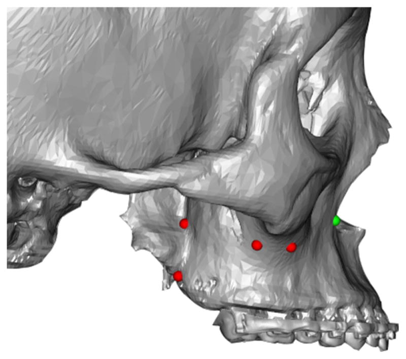
User defined cutting line. Red/Green dots are manually digitized to generate a user defined cutting plane. The green dot is the last digitized point
Fig. 3.
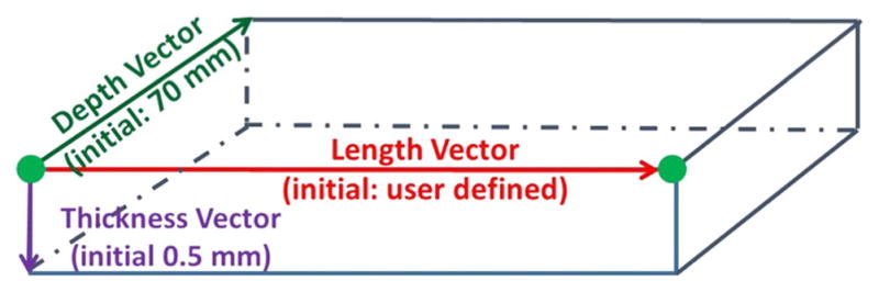
The hexahedron is formed between two adjacent (green) points following these initial dimensions
The next step is to chain all the hexahedrons together to form a “curved” virtual knife based on the digitized landmarks. If adjacent vertical faces of the hexahedrons are parallel (threshold: <1.0e−9), the two adjacent hexahedrons are combined into a single hexahedron. Otherwise, the two top faces of the hexahedrons are joined together by a hinge-axis joint, and two bottom faces are adaptively adjusted, either longer or shorter, depending on the direction of the angle. Figure 4 shows a “curved” virtual knife, the multi-connected hexahedrons, that is defined in Fig. 2. Finally, six control spheres are added to each hexahedron, allowing for manual adjustment of the length and orientation. A control panel is also available to translate, rotate, or adjust the thickness of the entire virtual knife.
Fig. 4.
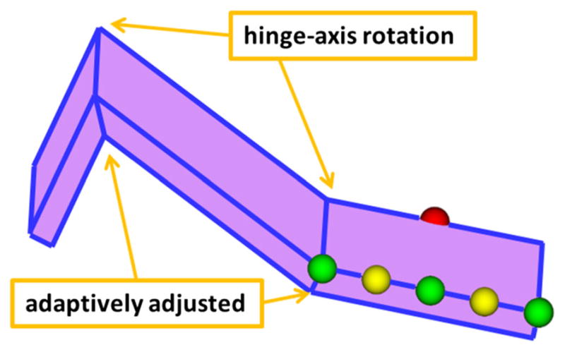
Hinge-axis joints combine the top faces of the hexahedrons, while the bottom faces are adaptively adjusted. The six control spheres also adjust the cutting plane. Green spheres, at each end, control the length of the hexahedron. The two middle green spheres (on each side of the hexahedron) control the width of the knife. Yellow spheres adjust angle between adjacent hexahedrons. The currently selected sphere is displayed in red
(2) To cut the 3D bone model into two bony segments
The cutting and separation of a 3D bone model into two bony segments is completed through triangle classification, “broken” triangle reconstruction, and capping the cutting surface. This process is described below in detail.
(a) To classify triangles that intersect with the multi-connected hexahedrons
The number of triangles in a 3D surface model is often excessive (e.g., 3 million). This is especially true on the models generated from CBCT scans. Therefore, a two-step coarse-to-fine algorithm was developed to efficiently classify all the triangles into four sets based on their relationship with the hexahedron knife. They are: outside set (no intersection), upper intersection set (intersection with the top face), lower intersection set (intersection with the bottom face), and inside set (completely inside the hexahedron) (Fig. 5).
Fig. 5.
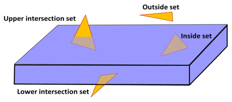
The four different relationships between a triangle and the hexahedron
The first step is to coarsely classify triangles into the outside set at the triangle level using a subdivision classification algorithm. The bounding box of a selected bone model is first divided into 64 evenly spaced elements that are used as basic units. A mesh collision detection algorithm [40] is then used to identify and mark all the elements that are outside of the virtual hexahedron knife. Afterward, the bounding box of each triangle in the bone model is mapped to its corresponding elements. If all the elements mapped by the triangle bounding box are “outside”, then this triangle is also classified as “outside”. No further calculation will be performed on this triangle.
After most of the “outside” triangles have been identified by coarse classification, the next step is to finely classify the remaining triangles at the vertex level. Each triangle has three vertices (v1, v2, and v3), and each vertex’s relationship to the hexahedron knife is defined using Eq. (1) below.
| (1) |
where I (v, fj) = Sign (ajx + bjy + cjz + dj) indicates the relationship between v and fj, and v = (x, y, z) represents the vertex of a given triangle; fj = ajx + bjy + cjz + dj represents one of the six plane functions of the hexahedron; a, b, c are three components of the normal vector of the plane j that points “out” of the hexahedron; and d is the offset of the plane from the origin of the global reference frame. If the solution of I (v, fj) is “−1”, the vertex is classified as “inside” the hexahedron. If the solution is “0”, the vertex is classified as “on” the hexahedron. Otherwise, the vertex is classified as “outside” the hexahedron. If a triangle has vertices related to multiple hexahedrons, then the triangle and its three adjacent neighbors are further divided into smaller triangles. This computation iterates until each triangle is related to only one hexahedron. Based on these rules, each triangle can now be classified as “outside”, “upper intersection”, “lower intersection”, or “inside” at the vertex level. At this point, all inside triangles are discarded (deleted), because they are inside the hexahedron knife. Only the upper and lower intersection triangles are further processed in the next step.
(b) To create new triangles to replace the “broken” triangles
The virtual knife will cut through all the upper and lower intersection triangles, resulting in “broken” triangles with two intersection points on each side of the triangle. “Broken” triangles are fixed based on the number of vertices that remain “outside” of the hexahedron. As shown in Fig. 6, if only one vertex is outside of the hexahedron, a new triangle is constructed using the vertex and the two intersection points. If two vertices of a triangle are outside the hexahedron, then two new triangles are constructed. Using this algorithm, the original “broken” triangles are replaced with new “intact” triangles.
Fig. 6.

Broken triangles are fixed depending on the number of vertices still outside (green) of the plane
(c) To separate the osteotomized model into two new bony segments
Since the 3D models are created by surface reconstruction, the cutting surface of osteotomized segments is open. Therefore, triangulated polygon surfaces are created to “cap” their corresponding segments (Fig. 6). To generate the cap, all intersecting edges between the bony model and the hexahedron surface are contoured. Next, a new surface is reconstructed by reorganizing, simplifying, and triangulating each contour. Afterward, all the outside, upper intersection, lower intersection triangles, and the cap for each segment are combined to form a temporary bone model. Finally, using the 3D region growing method, the temporary bone model is separated into the two osteotomized bony segments.
Module 5: surgical simulation
Once the required osteotomies are performed, doctors can simulate the desired orthognathic surgical procedure in this module. There are three major steps in surgical simulation: establishing a final dental occlusion between the upper and lower teeth, simulating a maxillary and a mandibular surgery by moving the related bony segments to a desired position, and simulating a genioplasty if necessary [20]. During the surgical simulation, all the 3D cephalometric measurements are updated in real-time, following the movements of the bony segments (Fig. 7a). The prerequisite for any surgical simulation is all the required bony segments for a surgery must exist, and their associated anatomical landmarks must be digitized. Because automatically establishes a customizable hierarchical structure for these bony segments, before the start of surgical simulation (Fig. 7b).
Fig. 7.

Before and after views of a virtually stimulated typical orthognathic surgery for a real patient: Le Fort I osteotomy, bilateral sagittal splint osteotomy and genioplasty. (a) The 3D cephalometry window shows measurements that is updated in real time during surgical simulation. (b) The hierarchy is used to organize bony segments and make sure all related segments are moved/rotated together. (c) A freehand 3D/2D measurement tool is used to ensure the bony collision is within clinical acceptable range and can be trimmed off during the surgical procedure
The first step of surgical simulation is to establish final dental occlusion. This is to restore the patient’s malocclusion to a normal occlusion. The final occlusion at maximum intercuspation (MI) is to be determined by surgeons on a set of stone dental models, prior to the surgical simulation [1,2,41,42]. The articulated stone dental models at MI are then scanned into the computer using a high-resolution laser or CBCT scanner, creating the final occlusal template [20]. Using this template, the lower teeth and its “child”, the mandibular distal segment, are placed to MI with the corresponding upper teeth of the maxillary Le Fort I segment. This is the desired relation between the maxilla and the mandible. However, this is only a temporary position, where only the desired relationship between the mandibular distal segment and the maxillary Le Fort I segment is established. In the following steps of surgical simulation, this relation is maintained by grouping the maxillary Le Fort I and the mandibular distal segments into the maxillomandibular combination.
The second step is to move all bony segments, including the maxillomandibular combination, into their final desired positions. Each segment can be moved and rotated in six degrees of freedom. The first surgical corrections (translation and rotation) are made to the maxillomandibular combination, usually around the maxillary dental midline point. Following the clinical protocol, surgical corrections are then performed in a specific sequence: midline correction (mediolateral correction), yaw correction, roll correction, vertical position adjustment, pitch adjustment, and finally anteroposterior position adjustment [20]. Afterward, the right and left proximal segments are aligned to the mandibular distal segment by rotating them around their center of rotation, located in the centers of their corresponding mandibular condyles.
The last step in surgical planning is to simulate a genioplasty. This step is optional. Its necessity is based on the doctor’s clinical judgement. The chin segment can be osteotomized either before or after the maxillomandibular combination is moved into the desired position. The chin segment is moved and rotated in six degrees of freedom around an anatomic landmark, the pogonion, which is located at the chin point.
Finally, the initial and final position of each bony segment can be visualized and compared using a “position review” function. A before and after view of a patient’s surgical simulation can be seen in Fig. 7.
Module 6: surgical splint/template
The final step of our surgical simulation is to design surgical splints, which are used to transfer the computerized surgical plan to the patient at the time of the surgery. The surgical splint is a horse-shoe-shaped teeth-anchored wafer that is placed between the upper and lower teeth. In a double-jaw surgical procedure, unlike the procedure seen in surgical simulation, the maxilla and the mandible are always osteotomized separately. One jaw is always osteotomized first and moved to the desired position, while the other jaw remains intact. Once the first jaw is in position, the other jaw is then osteotomized and moved to the desired position. Therefore, double-jaw surgeries require two splints: an intermediate and final splint. An intermediate splint is used to move the first osteotomized jaw to the desired position in relation to the intact opposite jaw. A final splint is used to position the second osteotomized jaw in relation to the first jaw. A doctor will decide which jaw to operate on first based on their clinical assessment, because different clinical indicators dictate maxillary or mandibular surgery first. However, in a single-jaw surgery, only one jaw is osteotomized and moved to the final desired position in relation to the intact jaw. Therefore, only a final splint is required. The procedure of streamline designing a surgical splint is described below in details [30].
(1) To select the type of splint to be designed
There are three possible types of surgical templates: an intermediate splint for maxillary surgery first, an intermediate splint for mandibular surgery first, and a final splint. Once the type of splint is selected, the upper and lower dental arches are automatically moved to the correct position for the intended type of surgery. For maxillary surgery first, the upper dental arch is displayed at its final position, while the lower dental arch is at its original position. The opposite is true for mandibular surgery first. For the final splint, both dental arches are displayed at their final positions.
(2) To autorotate the lower dental arch (optional)
When using an intermediate splint, only one jaw is moved to its final position, while the other intact jaw remains at its original position. This may cause collisions between the upper and lower teeth. To avoid this problem, the lower teeth needs to be autorotated around the center of rotation of the right and left condyles. The same rotation is also performed clinically at the time of the surgery. However, autorotation is usually not required for the final splint.
(3) To design the horse-shoe-shaped raw model of the splint
The first step is to digitize three landmarks on the occlusal surface of the upper dental arch to form a top plane for the splint. This plane is automatically offset 2 mm away from the occlusal surface to create enough anchorage (thickness) for the splint. The next step is to create a top contour for the top face of the splint by manually tracing the upper dental arch onto top plane using a cardinal spline (Fig. 8a).
Fig. 8.

Anatomy of our AnatomicAligner splint. a The contour of the top face of the splint is traced onto a plane. b Using the top and bottom contours, as well as, extensions if necessary, the surgical splint is generated by the AnatomicAligner
The bottom plane of the splint, for the lower dental arch, is created using the same steps as the top plane. The top contour is then copied to the bottom plane, forming the bottom contour, for the bottom face of the splint. It can then be manually edited to fit the lower dental arch. This is to ensure that both top and bottom contours have the same number of points.
If needed, a top and bottom contour extension can also be created by copying the corresponding contours and moving them 0.5 mm toward the occlusal surface. The contour extensions serve as transitional layers between the top and bottom face, in case there is a large positional discrepancy between the upper and lower teeth. This is common when designing the intermediate splint.
Collisions between contours are automatically detected to ensure the quality of the raw splint models. Each contour and its extension can be adjusted individually to avoid the collisions. Finally, corresponding points of each contour are automatically connected and triangulated, forming a surface model of the raw splint (Fig. 8b).
(4) To create the final model of the splint
The final model of the splint is generated by Boolean operation. It subtracts the upper and lower teeth from the raw splint model (Fig. 9a). The final model of the splint is exported as a .stl file and printed using any 3D printer that uses US Food and Drug Administration (FDA)-approved biocompatible material (Fig. 9b). The 3D printed intermediate and final splints are now ready to be used in the operating room during an orthognathic procedure (Fig. 9c).
Fig. 9.

Surgical splint. a A computerized intermediate splint (for maxillary surgery first) is shown with reconstructed bone models. The osteotomized Le Fort I segment is moved into its desired final position, while the mandibular distal segment remains intact at its original position. b The computerized splint is then printed using a 3D printer. c The printed surgical splint is finally used to reposition the Le Fort I segment at the time of surgery
Accuracy evaluation
Two evaluations have been completed to examine the accuracy of the AnatomicAligner system. In the first retrospective study, the accuracy of 3D models generated using the AnatomicAligner system was evaluated. In the second prospective study, the splints designed by the AnatomicAligner system were evaluated. Both studies were approved by our hospital Institutional Review Board [IRB(2)1011-0187x].
Validation #1
For the first validation, CT datasets of 30 historical patients were randomly selected from our digital patient archives using a random number table. These patients were diagnosed with dentofacial deformities and had underwent double-jaw orthognathic surgery. The accuracy of our AnatomicAligner system was evaluated and compared to the industry gold standard, Mimics 17.0 (Materialise NV, Leuven, Belgium), in the following areas: (1) CT model reconstruction, (2) virtual osteotomy, and (3) translational and rotational movements. To our knowledge, no currently available commercial software is capable of transferring recorded NHP to 3D models or performing true 3D cephalometric analysis. Therefore, some of the unique functions in our system, e.g., NHP and 3D cephalometry, could not be evaluated.
To evaluate the accuracy of CT model reconstruction, the DICOM dataset of the same patient was imported into both systems. The masks of the skeletal structure of the head were initially created using a predetermined threshold (grayscale: 1250). Then, both masks were manually edited to remove the spine by removing the spine mask on the same sequential axial slice. Finally, using region growing in each system, masks of the skull were created. The 3D skull models were reconstructed in high resolution (sampling 2:2:1 in x, y, z) using Marching Cubes algorithm in AnatomicAligner and a proprietary algorithm in Mimics. To compare the two models, RapidForm software (INUS Technology, Korea) was used to compute the surface deviation between the two models. Surface deviation between the two models was calculated as the absolute mean Euclidean distance. Both the mean and standard deviation (SD) were recorded. Since the origins of the coordinate systems were different between the two systems, the Mimics model was registered (translation only) to the AnatomicAligner model, in RapidForm.
To evaluate the accuracy of virtual osteotomy, we compared osteotomized segments generated by both systems. In order to avoid confounding errors that might be the result of segmentation and 3D reconstruction, a single midface model, generated in the AnatomicAligner, was imported into both systems. A Le Fort I osteotomy was then performed in both systems following the clinical standard. In the AnatomicAligner, the cut was made using the “virtual osteotomy” function, whereas the “PolyPlane” function was used in Mimics. Two bony segments were generated in each system: a Le Fort I segment and the remaining of the midface segment. The surface deviation for both Le Fort I and the remaining midface segments generated by the two systems were calculated in RapidForm.
Finally, to evaluate the accuracy of translational and rotational movements, the surface deviation was calculated between the 3D models of the two systems after a specific transformation matrix was applied. The Le Fort I segment generated by the AnatomicAligner for comparing virtual osteotomy was used in both systems. This is done to avoid confounding errors from 3D reconstruction and/or virtual osteotomy. Once the Le Fort I segment had been imported into both systems, it was duplicated. The first Le Fort I segment was translated 4 mm along the x axis, 6 mm along the y axis, and 8 mm along the z axis. The second Le Fort I segment was rotated 6° around the x axis, 8° around the y axis, and 10° around the z axis. The two Le Fort I segments were once again imported into RapidForm, and surface deviation between the corresponding models was calculated.
Validation #2
The purpose of this prospective validation was to determine whether the planned results, using the AnatomicAligner system, were at least as good as the current gold standard (designed and printed by commercial services). Ten consecutive patients were included based on the following criteria: (1) patients who were diagnosed with a dentofacial deformity; (2) patients who were scheduled for double-jaw surgery; and (3) patients who had CT scans as a part of their diagnosis and treatment. For each patient, the orthognathic surgery was planned by a single surgeon (J.G.) in conjunction with a commercial service provider (3D Systems—Medical Modeling, Golden, CO) following the author’s CASS protocol [3,20]. Surgical splints (denoted as “commercial splints”) were designed and printed by the commercial service provider, and these splints were used at the time of surgery. The same surgeon then repeated the same surgical planning using the AnatomicAligner system, from importing the DICOM images to designing the surgical splints. The transformation matrix used by the service provider was then duplicated in the AnatomicAligner system and applied to each bony segment. Finally, the intermediate splint designed in the AnatomicAligner (denoted as “AnatomicAligner splint”) was printed by a 3D printer (Object30 Orthodesk, Stratasys Ltd, Eden Prairie, MN) using FDA-approved MED610 material. Only the intermediate splint was evaluated. This is because the position of the intermediate splint is directly determined by the system. Therefore, the accuracy of the intermediate splint is the most direct benchmark for measuring the accuracy of the system.
The fitting of the printed commercial and AnatomicAligner splints were evaluated by two experienced oral urgeons for orthognathic surgery (H.M. and D.H.) in the following aspects: total fitting (relationship of the upper and lower models) and individual fitting (rocking and shifting). Neither evaluator was involved in the surgical planning or splint printing. The evaluators were also blinded from each other’s evaluation results. However, since the materials used to print splint by our laboratory and the commercial service were different, it was impossible to blind the evaluators from the system used to design the splint. Therefore, the following strategy was used to prevent conformation bias. For each patient, the commercial splint was used to mount the upper and lower stone dental models onto a Galetti dental articulator. Afterward, the commercial splint was removed, and the AnatomicAligner splint was inserted for the evaluation. The evaluators were then asked to evaluate the fitting of the splint based on the clinical standard. The most important aspect was to determine whether the AnatomicAligner splint could correctly establish the desired intermediate occlusion between the upper and lower teeth. To do this, the fitting of the AnatomicAligner splint was evaluated, while both the upper and lower stone models were mounted on the Galetti dental articulator, a relationship that was predetermined by the commercial splint. Once the total fitting was evaluated, the rocking and shifting on the individual upper and lower dental models were evaluated individually. Three ranks were given for each splint in each respect: Rank #1 represented perfect fit, Rank #2 represented a partial fit (mild shifting or rocking), and Rank #3 represented no fit at all. Finally, the ranking scores determined by the two evaluators were paired and summarized descriptively.
Results
Results for validation #1
The average surface deviation between the two models after 3D model reconstruction in Mimics and CASS was 0.3 mm with a SD of 0.03 mm. These errors were mainly attributed to scattering at the margins of the image, where the images exceeded field of view during CT acquisition, thin bones in the nasal cavity and orbital frames, and artifacts caused by amalgam and orthodontic bands (Fig. 10). Once these errors were removed, the average surface deviation was reduced to less than 0.2 mm. These error margins are clinically insignificant.
Fig. 10.

Average surface deviation between the AnatomicAligner and Mimics models after segmentation and 3D model reconstruction
Furthermore, the results of our virtual osteotomy comparison showed an average surface deviation of 0.001 mm between the two Le Fort I segments with a SD of 0.001 mm. The results of the translation comparison showed an average surface deviation of 0.001 mm with a SD of 0.001 mm between the two Le Fort I segments. And finally, the results of the rotational comparison showed an average surface deviation of 0.01 mm with a SD of 0.01 mm.
Results for validation #2
The evaluation results showed that all the AnatomicAligner splints fit perfectly (Rank #1), while the models were mounted in the intermediate occlusion on a Galetti dental articulator. Figure 11 shows the results of total splint fitting evaluation of a set of randomly selected patient models. In addition, all the AnatomicAligner splints were seated perfectly on the stone models, without any rocking (Rank #1) or shifting (Rank #1) while they were evaluated individually on the upper and lower models.
Fig. 11.

The result of the total splint fitting evaluation. a Mounting the upper and lower stone dental models onto a Galetti dental articulator using the commercial splint; b The commercial splint was removed, and the AnatomicAligner splint was inserted for the fitting evaluation without breaking the relationship established by the commercial splint
Discussion and conclusion
We successfully developed a CASS system, the AnatomicAligner, for planning orthognathic surgery. The system will soon be available for free to the broader clinical and research communities. The advantages of this AnatomicAligner system over other research and commercially available systems are as follows. The first advantage is that it allows doctors, for the first time, to accurately plan an entire orthognathic surgery within a single software system following our streamlined clinical protocol [4]. The user interface of the system is designed with the perception that end users are medical doctors with little knowledge in computer graphics. Necessary prompts and self-error-checks are also implemented to guide and warn the users. The second advantage is that the true 3D cephalometric analysis [7], including the five geometric properties of orientation, symmetry, position, size and shape, is implemented in a surgical planning system for the first time. This is especially important for correctly quantifying deformities and planning treatment. The third advantage is that all involved bony segments are moved and rotated under an automatically generated hierarchical structure during the registration and surgical simulation. This makes possible to efficiently plan different types of surgeries without manually relinking or regrouping the related bony segments repeatedly. The final advantage is that the surgical splint design is a semiautomatic procedure. To our knowledge, the authors are the first group to report this streamlined and guided splint designing method [30]. The surgical splints can be effectively designed in the system and printed by any in-house 3D printer that uses FDA-approved biocompatible materials. These splints are used at the time of the surgery to accurately transfer the computerized surgical plan to the patient. Currently, we have obtained our hospital’s IRB approval and started to use this system in our patient care for treating patients with dentofacial deformities.
Nonetheless, the AnatomicAligner system also has several limitations. The first limitation is that the stone dental models are still needed to establish the final occlusion, as indicated in our clinical protocol [20]. Although our laboratory and several others are trying to automate the establishment of final occlusion without using the stone dental models [41–45], it is still under rigorous clinical testing. The second limitation is soft-tissue-change prediction following the osteotomies. As a clinical application, the prediction must be fast and accurate. Yet attaining both is difficult because these attributes are inversely related. Several models have been used to simulate soft-tissue deformations both commercially and in research, including: empirical-based models [8,9,46,47], mass spring models [48–50], mass tensor models [51,52] and finite element models (FEM) [47,49,51–56]. Among these, FEM is reported to be the most common, accurate and biomechanically relevant method [57–60]. However, preparation and computation time for FEM is significant (from hours to days). Our laboratory has also solved this problem by using an eFace-template method to efficiently generate a patient-specific and anatomically detailed facial soft tissue FEM within minutes [61–63], which is also under rigorous clinical testing now. We hope to incorporate both features into our AnatomicAligner system in the near future.
Acknowledgments
The author would like to thank Chien-Ming Chang, D.D.S., Yi-Fang Lo, D.D.S., Shunyao Shen D.D.S., M.S., Xiaoyan Zhang, Ph.D., Ken-Chung Chen, D.D.S., M.S., Zhen Tang, D.D.S., M.S., Ph.D., and Xiaobo Zhou, Ph.D., for their contributions on this project. The preliminary study of this manuscript was presented in part at 7th International Conference on Medical Imaging and Augmented Reality (MIAR) in Bern, Switzerland on August 24–26, 2016.
Funding This study is funded in part by the United States National Institutes of Health/National Institute of Dental and Craniofacial Research (NIH/NIDCR) Grants (R01DE022676 and R01DE021863). Dr. Mai was sponsored by Scholar Award of Guangxi Education Department, Guangxi, China, and Dr. Ho was sponsored by Taipei Municipal Wan Fang Hospital Taipei, Taiwan (ROC), while working at the Surgical Planning Laboratory, Department of Oral and Maxillofacial Surgery, Houston Methodist Research Institute, Houston, TX, USA.
Footnotes
Compliance with ethical standards
Conflict of interest The authors declare that they have no conflict of interest.
Ethical approval The study was approved by our IRB [approval number: IRB(2)1011-0187x]. All procedures performed in studies involving human participants were in accordance with the ethical standards of the institutional and/or national research committee and with the 1964 Helsinki declaration and its later amendments or comparable ethical standards. This article does not contain any studies with animals performed by any of the authors.
Informed consent Due to the fact that this study only utilized historical data that had been collected as a part of the medical records during the patient care, informed consent is not required.
References
- 1.Bell WH. Surgical correction of dentofacial deformities. WB Saunders; Philadelphia: 1980. [Google Scholar]
- 2.Bell WH. Modern practice in orthognathic and reconstructive surgery. WB Saunders; Philadelphia: 1992. [Google Scholar]
- 3.Xia JJ, Gateno J, Teichgraeber JF. New clinical protocol to evaluate craniomaxillofacial deformity and plan surgical correction. J Oral Maxillofac Surg. 2009;67(10):2093–2106. doi: 10.1016/j.joms.2009.04.057. [DOI] [PMC free article] [PubMed] [Google Scholar]
- 4.Altobelli DE, Kikinis R, Mulliken JB, Cline H, Lorensen W, Jolesz F. Computer-assisted three-dimensional planning in craniofacial surgery. Plast Reconstr Surg. 1993;92(4):576–585. (discussion 586–577) [PubMed] [Google Scholar]
- 5.Montgomery K, Stephanides M, Schendel S. Development and application of a virtual environment for reconstructive surgery. Comput Aided Surg. 2000;5(2):90–97. doi: 10.1002/1097-0150(2000)5:2<90::AID-IGS3<3.0.CO;2-7. [DOI] [PubMed] [Google Scholar]
- 6.Xia J, Wang D, Samman N, Yeung RW, Tideman H. Computer-assisted three-dimensional surgical planning and simulation: 3D color facial model generation. Int J Oral Maxillofac Surg. 2000;29(1):2–10. [PubMed] [Google Scholar]
- 7.Xia J, Ip HH, Samman N, Wang D, Kot CS, Yeung RW, Tideman H. Computer-assisted three-dimensional surgical planning and simulation: 3D virtual osteotomy. Int J Oral Maxillofac Surg. 2000;29(1):11–17. [PubMed] [Google Scholar]
- 8.Xia J, Ip HH, Samman N, Wong HT, Gateno J, Wang D, Yeung RW, Kot CS, Tideman H. Three-dimensional virtual-reality surgical planning and soft-tissue prediction for orthognathic surgery. IEEE Trans Inf Technol Biomed. 2001;5(2):97–107. doi: 10.1109/4233.924800. [DOI] [PubMed] [Google Scholar]
- 9.Xia J, Samman N, Yeung RW, Wang D, Shen SG, Ip HH, Tideman H. Computer-assisted three-dimensional surgical planing and simulation. 3D soft tissue planning and prediction. Int J Oral Maxillofac Surg. 2000;29(4):250–258. [PubMed] [Google Scholar]
- 10.Xia JJ, Gateno J, Teichgraeber JF. Three-dimensional computer-aided surgical simulation for maxillofacial surgery. Atlas Oral Maxillofac Surg Clin North Am. 2005;13(1):25–39. doi: 10.1016/j.cxom.2004.10.004. [DOI] [PubMed] [Google Scholar]
- 11.Swennen GR, Schutyser F. Three-dimensional cephalometry: spiral multi-slice vs cone-beam computed tomography. Am J Orthod Dentofacial Orthop. 2006;130(3):410–416. doi: 10.1016/j.ajodo.2005.11.035. [DOI] [PubMed] [Google Scholar]
- 12.Swennen GR, Barth EL, Eulzer C, Schutyser F. The use of a new 3D splint and double CT scan procedure to obtain an accurate anatomic virtual augmented model of the skull. Int J Oral Maxillofac Surg. 2007;36(2):146–152. doi: 10.1016/j.ijom.2006.09.019. [DOI] [PubMed] [Google Scholar]
- 13.Gateno J, Xia JJ, Teichgraeber JF, Christensen AM, Lemoine JJ, Liebschner MA, Gliddon MJ, Briggs ME. Clinical feasibility of computer-aided surgical simulation (CASS) in the treatment of complex cranio-maxillofacial deformities. J Oral Maxillofac Surg. 2007;65(4):728–734. doi: 10.1016/j.joms.2006.04.001. [DOI] [PubMed] [Google Scholar]
- 14.Sadiq Z, Collyer J, Sneddon K, Walsh S. Orthognathic treatment of asymmetry: two cases of “waferless” stereotactic maxillary positioning. Br J Oral Maxillofac Surg. 2012;50(2):e27–29. doi: 10.1016/j.bjoms.2011.07.016. [DOI] [PubMed] [Google Scholar]
- 15.Polley JW, Figueroa AA. Orthognathic positioning system: intraoperative system to transfer virtual surgical plan to operating field during orthognathic surgery. J Oral Maxillofac Surg. 2013;71(5):911–920. doi: 10.1016/j.joms.2012.11.004. [DOI] [PubMed] [Google Scholar]
- 16.Bobek S, Farrell B, Choi C, Farrell B, Weimer K, Tucker M. Virtual surgical planning for orthognathic surgery using digital data transfer and an intraoral fiducial marker: the charlotte method. J Oral Maxillofac Surg. 2015;73(6):1143–1158. doi: 10.1016/j.joms.2014.12.008. [DOI] [PubMed] [Google Scholar]
- 17.Ullah R, Turner PJ, Khambay BS. Accuracy of three-dimensional soft tissue predictions in orthognathic surgery after Le Fort I advancement osteotomies. Br J Oral Maxillofac Surg. 2015;53(2):153–157. doi: 10.1016/j.bjoms.2014.11.001. [DOI] [PubMed] [Google Scholar]
- 18.Li B, Shen SG, Yu H, Li J, Xia JJ, Wang X. A new design of CAD/CAM surgical template system for two-piece narrowing genioplasty. Int J Oral Maxillofac Surg. 2016;45(5):560–566. doi: 10.1016/j.ijom.2015.10.013. [DOI] [PMC free article] [PubMed] [Google Scholar]
- 19.Chen X, Xu L, Sun Y, Politis C. A review of computer-aided oral and maxillofacial surgery: planning, simulation and navigation. Expert Rev Med Devices. 2016;13(11):1043–1051. doi: 10.1080/17434440.2016.1243054. [DOI] [PubMed] [Google Scholar]
- 20.Xia JJ, Gateno J, Teichgraeber JF, Yuan P, Chen KC, Li J, Zhang X, Tang Z, Alfi DM. Algorithm for planning a double-jaw orthognathic surgery using a computer-aided surgical simulation (CASS) protocol. Part 1: planning sequence. Int J Oral Maxillofac Surg. 2015;44(12):1431–1440. doi: 10.1016/j.ijom.2015.06.006. [DOI] [PMC free article] [PubMed] [Google Scholar]
- 21.Gateno J, Xia J, Teichgraeber JF, Rosen A. A new technique for the creation of a computerized composite skull model. J Oral Maxillofac Surg. 2003;61(2):222–227. doi: 10.1053/joms.2003.50033. [DOI] [PubMed] [Google Scholar]
- 22.Schatz EC, Xia JJ, Gateno J, English JD, Teichgraeber JF, Garrett FA. Development of a technique for recording and transferring natural head position in 3 dimensions. J Craniofac Surg. 2010;21(5):1452–1455. doi: 10.1097/SCS.0b013e3181ebcd0a. [DOI] [PubMed] [Google Scholar]
- 23.Xia JJ, McGrory JK, Gateno J, Teichgraeber JF, Dawson BC, Kennedy KA, Lasky RE, English JD, Kau CH, McGrory KR. A new method to orient 3-dimensional computed tomography models to the natural head position: a clinical feasibility study. J Oral Maxillofac Surg. 2011;69(3):584–591. doi: 10.1016/j.joms.2010.10.034. [DOI] [PMC free article] [PubMed] [Google Scholar]
- 24.Gateno J, Xia JJ, Teichgraeber JF. New 3-dimensional cephalometric analysis for orthognathic surgery. J Oral Maxillofac Surg. 2011;69(3):606–622. doi: 10.1016/j.joms.2010.09.010. [DOI] [PMC free article] [PubMed] [Google Scholar]
- 25.Xia JJ, Gateno J, Teichgraeber JF, Yuan P, Li J, Chen KC, Jajoo A, Nicol M, Alfi DM. Algorithm for planning a double-jaw orthognathic surgery using a computer-aided surgical simulation (CASS) protocol. Part 2: three-dimensional cephalometry. Int J Oral Maxillofac Surg. 2015;44(12):1441–1450. doi: 10.1016/j.ijom.2015.06.007. [DOI] [PMC free article] [PubMed] [Google Scholar]
- 26.Gateno J, Jajoo A, Nicol M, Xia JJ. The primal sagittal plane of the head: a new concept. Int J Oral Maxillofac Surg. 2016;45(3):399–405. doi: 10.1016/j.ijom.2015.11.013. [DOI] [PMC free article] [PubMed] [Google Scholar]
- 27.Gateno J, Xia J, Teichgraeber JF, Rosen A, Hultgren B, Vadnais T. The precision of computer-generated surgical splints. J Oral Maxillofac Surg. 2003;61(7):814–817. doi: 10.1016/s0278-2391(03)00240-4. [DOI] [PubMed] [Google Scholar]
- 28.Hsu SS, Gateno J, Bell RB, Hirsch DL, Markiewicz MR, Teichgraeber JF, Zhou X, Xia JJ. Accuracy of a computer-aided surgical simulation protocol for orthognathic surgery: a prospective multicenter study. J Oral Maxillofac Surg. 2013;71(1):128–142. doi: 10.1016/j.joms.2012.03.027. [DOI] [PMC free article] [PubMed] [Google Scholar]
- 29.Schwartz HC. Does computer-aided surgical simulation improve efficiency in bimaxillary orthognathic surgery? Int J Oral Maxillofac Surg. 2014;43(5):572–576. doi: 10.1016/j.ijom.2013.10.018. [DOI] [PubMed] [Google Scholar]
- 30.Yuan P, Ho DC-Y, Chang C-M, Li J, Mai H, Kim D, Shen S, Zhang X, Zhou X, Xiong Z, Gateno J, Xia JJ. A novel computer-aided surgical simulation (CASS) system for streamline orthognathic surgical planning. Paper presented at the 7th international conference of medical imaging and augmented reality (MIAR) (2016); Bern, Switzerland. August 24–26, 2016.2016. [Google Scholar]
- 31.Schatz EC. A new technique for recording natural head position in three dimensions. In: Xia JJ, English JD, Garrett FA, et al., editors. MS thesis. The University of Texas Health Science Center at Houston; Houston: 2006. Advisors. [Google Scholar]
- 32.Lorensen WE, Cline HE. Marching cubes: A high resolution 3D surface construction algorithm. ACM SIGGRAPH Computer Graphics.SIGGRAPH ’87 proceedings of the 14th annual conference on computer graphics and interactive techniques; New York, NY. 1987. [Google Scholar]
- 33.Xia J, Samman N, Yeung RW, Shen SG, Wang D, Ip HH, Tideman H. Three-dimensional virtual reality surgical planning and simulation workbench for orthognathic surgery. Int J Adult Orthod Orthognath Surg. 2000;15(4):265–282. [PubMed] [Google Scholar]
- 34.Damstra J, Fourie Z, Ren Y. Simple technique to achieve a natural position of the head for cone beam computed tomography. Br J Oral Maxillofac Surg. 2010;48(3):236–238. doi: 10.1016/j.bjoms.2009.10.001. [DOI] [PubMed] [Google Scholar]
- 35.Athanasiou AE. Orthodontic cephalometry. Mosby-Wolfe; St. Louis: 1995. [Google Scholar]
- 36.Gateno J, Xia JJ, Teichgraeber JF. Effect of facial asymmetry on 2-dimensional and 3-dimensional cephalometric measurements. J Oral Maxillofac Surg. 2011;69(3):655–662. doi: 10.1016/j.joms.2010.10.046. [DOI] [PMC free article] [PubMed] [Google Scholar]
- 37.Swennen GR, Schutyser F, Barth EL, De Groeve P, De Mey A. A new method of 3-D cephalometry Part I: the anatomic Cartesian 3-D reference system. J Craniofac Surg. 2006;17(2):314–325. doi: 10.1097/00001665-200603000-00019. [DOI] [PubMed] [Google Scholar]
- 38.Zelditch ML, Swiderski DL, Sheets HD. Geometric morphometrics for biologists: a primer. Elsevier; London: 2012. [Google Scholar]
- 39.Li J, Yuan P, Chang C-M, Ho DC-Y, Lo Y-F, Shen S, Kim D, Teichgraeber JF, Alfi DM, Gateno J, Xia JJ. New approach to establish an object reference frame for dental arch in computer-aided surgical simulation (CASS) Int J Oral Maxillofac Surg. 2017 doi: 10.1016/j.ijom.2017.04.012. (in press) [DOI] [PMC free article] [PubMed] [Google Scholar]
- 40.Gottschalk S, Lin MC, Manocha D. OBBTree: a hierarchical structure for rapid interference detection. Paper presented at the proceedings of ACM Siggraph ’96.1996. [Google Scholar]
- 41.Chang YB, Xia JJ, Gateno J, Xiong Z, Zhou X, Wong ST. An automatic and robust algorithm of reestablishment of digital dental occlusion. IEEE Trans Med Imaging. 2010;29(9):1652–1663. doi: 10.1109/TMI.2010.2049526. [DOI] [PMC free article] [PubMed] [Google Scholar]
- 42.Chang YB, Xia JJ, Gateno J, Xiong Z, Teichgraeber JF, Lasky RE, Zhou X. In vitro evaluation of new approach to digital dental model articulation. J Oral Maxillofac Surg. 2012;70(4):952–962. doi: 10.1016/j.joms.2011.02.109. [DOI] [PMC free article] [PubMed] [Google Scholar]
- 43.Xia JJ, Chang YB, Gateno J, Xiong Z, Zho X. Automated digital dental articulation. Med Image Comput Comput Assist Interv. 2010;13(Pt 3):278–286. doi: 10.1007/978-3-642-15711-0_35. [DOI] [PMC free article] [PubMed] [Google Scholar]
- 44.Li J, Ferraz F, Shen S, Lo Y-F, Zhang X, Yuan P, Tang Z, Chen K-C, Gateno J, Zhou X, Xia JJ. Automated three-piece digital dental articulation. In: Navab N, Hornegger J, Wells WM, Frangi AF, editors. Medical image computing and computer-assisted intervention—MICCAI 2015, lecture notes in computer science; Munich, Germany. October 5–9, 2015; Springer; 2015. pp. 488–496. [Google Scholar]
- 45.Nadjmi N, Mollemans W, Daelemans A, Van Hemelen G, Schutyser F, Berge S. Virtual occlusion in planning orthognathic surgical procedures. Int J Oral Maxillofac Surg. 2010;39(5):457–462. doi: 10.1016/j.ijom.2010.02.002. [DOI] [PubMed] [Google Scholar]
- 46.Meller S, Nkenke E, Kalender WA. Statistical face models ofr the prediction of soft-tissue deformations after orthognathic osteotomies. MICCAI LNCS. 2005;3750:443–450. doi: 10.1007/11566489_55. [DOI] [PubMed] [Google Scholar]
- 47.Keeve E, Girod S, Kikinis R, Girod B. Deformable modeling of facial tissue for craniofacial surgery simulation. Comput Aided Surg. 1998;3(5):228–238. doi: 10.1002/(SICI)1097-0150(1998)3:5<228::AID-IGS2>3.0.CO;2-I. [DOI] [PubMed] [Google Scholar]
- 48.Nedel LP, Thalmann D. Real time muscle deformations using mass-spring systems. Proceedings of the Computer Graphics International; Hannover, Germany. 1998. pp. 156–166. [Google Scholar]
- 49.Chen F, Gu L, Huang P, Zhang J, Xu J. Soft tissue modeling using nonlinear mass spring and simplified medial representation. Conf Proc IEEE Eng Med Biol Soc. 2007;2007:5083–5086. doi: 10.1109/IEMBS.2007.4353483. [DOI] [PubMed] [Google Scholar]
- 50.Maal TJ, Plooij JM, Rangel FA, Mollemans W, Schutyser FA, Berge SJ. The accuracy of matching three-dimensional photographs with skin surfaces derived from cone-beam computed tomography. Int J Oral Maxillofac Surg. 2008;37(7):641–646. doi: 10.1016/j.ijom.2008.04.012. [DOI] [PubMed] [Google Scholar]
- 51.Marchetti C, Bianchi A, Bassi M, Gori R, Lamberti C, Sarti A. Mathematical modeling and numerical simulation in maxillo-facial virtual surgery (VISU) J Craniofac Surg. 2006;17(4):661–667. doi: 10.1097/00001665-200607000-00009. (discussion 668) [DOI] [PubMed] [Google Scholar]
- 52.Marchetti C, Bianchi A, Bassi M, Gori R, Lamberti C, Sarti A. Mathematical modeling and numerical simulation in maxillofacial virtual surgery. J Craniofac Surg. 2007;18(4):826–832. doi: 10.1097/scs.0b013e318068434b. [DOI] [PubMed] [Google Scholar]
- 53.Cover SA, Ezquerra NF, O’Brien JF. Interactively deformable models for surgery simulation. IEEE Comput Graph Appl. 1993;13:68–75. [Google Scholar]
- 54.Gori R, Sarti A, Lamberti C, Fares JE, Marchetti C. Maxillofacial virtual surgery from 3D CT images. Paper presented at the bioengineering science and supercomputing at CINECA report.2001. [Google Scholar]
- 55.Binucci MM, Lamberti C, Gori R, Montagna L, Sarti A. An integrated system for maxillo-facial surgery simulation. Paper presented at the CARS.2002. [Google Scholar]
- 56.Koch RM, Gross MH, Carls FR, von Buren DF, Frankhauser G, Parish YIH. Simulating facial surgery using finite element models. SIGGRAPH; ACM Press; 1996. pp. 421–428. [Google Scholar]
- 57.Pan BB, Zhang GM, Xia JJ, Yuan P, Ip HHS, He QZ, Lee PKM, Chow B, Zhou XB. Prediction of soft tissue deformations after CMF surgery with incremental kernel ridge regression. Comput Biol Med. 2016;75:1–9. doi: 10.1016/j.compbiomed.2016.04.020. [DOI] [PMC free article] [PubMed] [Google Scholar]
- 58.Pan B, Xia JJ, Yuan P, Gateno J, Ip HH, He Q, Lee PK, Chow B, Zhou X. Incremental kernel ridge regression for the prediction of soft tissue deformations. Med Image Comput Comput Assist Interv. 2012;15(Pt 1):99–106. doi: 10.1007/978-3-642-33415-3_13. [DOI] [PMC free article] [PubMed] [Google Scholar]
- 59.Kim H, Jurgens P, Nolte LP, Reyes M. Anatomically-driven soft-tissue simulation strategy for cranio-maxillofacial surgery using facial muscle template model. Med Image Comput Comput Assist Interv. 2010;13(Pt 1):61–68. doi: 10.1007/978-3-642-15705-9_8. [DOI] [PubMed] [Google Scholar]
- 60.Mollemans W, Schutyser F, Nadjmi N, Maes F, Suetens P. Predicting soft tissue deformations for a maxillofacial surgery planning system: from computational strategies to a complete clinical validation. Med Image Anal. 2007;11(3):282–301. doi: 10.1016/j.media.2007.02.003. [DOI] [PubMed] [Google Scholar]
- 61.Kim D, Chang CM, Ho DC-Y, Zhang X, Shen S, Yuan P, Mai H, Zhang G, Zhou X, Gateno J, Liebschner MAK, Xia JJ. Two-stage simulation method to improve facial soft tissue prediction accuracy for orthognathic surgery. In: Ourselin S, Joskowicz L, Sabuncu MR, Unal G, Wells WM, editors. Medical image computing and computer-assisted intervention—MICCAI 2016, lecture notes in computer science; Athens, Greece. October 17–21, 2016; Springer; 2016. pp. 559–567. [Google Scholar]
- 62.Zhang X, Tang Z, Liebschner MA, Kim D, Shen S, Chang CM, Yuan P, Zhang G, Gateno J, Zhou X, Zhang SX, Xia JJ. An eFace-template method for efficiently generating patient-specific anatomically-detailed facial soft tissue FE models for craniomaxillofacial surgery simulation. Ann Biomed Eng. 2015 doi: 10.1007/s10439-015-1480-7. [DOI] [PMC free article] [PubMed] [Google Scholar]
- 63.Zhang G, Xia JJ, Liebschner M, Zhang X, Kim D, Zhou X. Improved Rubin-Bodner model for the prediction of soft tissue deformations. Med Eng Phys. 2016;38(11):1369–1375. doi: 10.1016/j.medengphy.2016.09.008. [DOI] [PMC free article] [PubMed] [Google Scholar]