Abstract
Helicoidal fibre structures are widely observed in natural materials. In this paper, an integrated experimental and analytical approach was used to investigate the compressive resistance of helicoidal fibre structures. First, helicoidal fibre-reinforced composites were created using three-dimensionally printed helicoids and polymeric matrices, including plain, ring-reinforced and helix-reinforced helicoids. Then, load–displacement curves under monotonic compression tests were collected to measure the compressive strengths of helicoidal fibre composites. Fractographic characterization was performed using an X-ray microtomographer and scanning electron microscope, through which crack propagations in helicoidal structures were illustrated. Finally, mathematical modelling was performed to reveal the essential fibre architectures in the compressive resistance of helicoidal fibre structures. This work reveals that fibre–matrix ratios, helix pitch angles and interlayer rotary angles are critical to the compressive resistance of helicoidal structures.
Keywords: helicoidal structures, fibre-reinforced composites, three-dimensional printing, compressive resistance
1. Introduction
Helicoidal structures are widely found in biological systems [1–4], such as lobsters [5,6], mantis shrimps [7,8], crabs [9,10], human bones [11,12], bamboo [13] and wood [14]. In helicoids, successive fibres rotate at small angles to the longitudinal axis, making them effective in resisting cracks across layers by continuously diverting crack directions. Different reinforcements are found in natural materials to shield the helicoidal structures, such as mantis shrimps [7], crabs [15], human meniscus [16,17] and plant cells [18]. For example, Weaver et al. [7] found that thickened circumferential bands with parallel chitin fibres surround the periodic regions with helicoidal fibre structures in mantis shrimp (figure 1a), which constrain the helicoids radially. Meyers et al. [15] disclosed that the crab carapace comprises a hard, mineralized component and a softer, organized component. The brittle components are organized in helicoids, while the soft tubules with canals surround the brittle helicoidal cores to strengthen the structure (figure 1b). Similarly, both circumferential and radial fibres exist in human meniscus [16,17]. The interplay between the radial fibre helicoids and circumferential fibres reinforces the entire meniscus structure.
Figure 1.
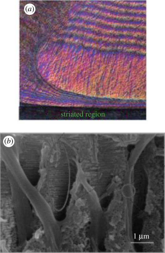
Examples of reinforced helicoids in nature. (a) Parallel chitin fibres surrounding the periodic regions with helicoidal fibre structures in mantis shrimp. (Adapted from [19].) (b) Tube structures around the helicoidal fibres of spider crabs. (Adapted from [15].) (Online version in colour.)
Recently, these natural prototypes have motivated the creation of various bioinspired materials and structures using three-dimensional (3D) printing techniques [20–24]. Milliron [19] created 3D-printed helicoids with and without ring reinforcements. By using single-edge notched specimens, helicoids with ring reinforcements exhibited higher fracture loads than non-reinforced helicoids, and helical fractural surfaces were observed along successive fibre layers. Ribbans et al. [22] studied the interlaminar resistance of helicoidal fibre structures. The results showed that ring and helix reinforcements exhibited cutting-and-delaminating crack patterns under pure shear stresses. The related modelling work revealed that fibre–matrix modulus ratios and pitch angles of helix reinforcements were essential to the interlaminar shear resistance of helicoidal structures. Yang et al. [16] used electrically assisted 3D-printing techniques to produce different helicoidal carbon nanotube-reinforced polymeric composites. They reported that a smaller interlayer angle in helicoids leads to greater energy dissipation and impact resistance.
Meanwhile, helicoid-inspired, fibre-reinforced polymeric composites have also been created using different fibres and matrices [25–28]. Grunenfelder et al. [25] created three types of helicoidal composite plates by stacking rotated unidirectional plies at 7.8°, 16.3° and 25.7°, respectively. During impact tests, smooth damage patterns transited between plies, resulting in a reduction of through-thickness damage and an increment of residual strength over quasi-isotropic composites with 45° cross-plies. Shang et al. [26] created carbon fibre-reinforced epoxy helicoidal composites at interlayer rotary angles of 10° and 18°. By indenting the composite plates, helicoidal composites with a 10° angle exhibited improved peak loads over control specimens with 90° cross-plies. Both delaminated fibre–matrix interfaces and fractured fibres were detected in failed specimens, in which deteriorated spiral damage penetrated along the depth. Yaraghi et al. [27] studied the 3D-printed sinusoidally architected helicoidal structures. The results showed that sinusoidal herringbone architecture enabled an enhancement of stress redistributions and out-of-plane stiffness compared with helicoidal architecture.
Different mathematical models have been proposed to investigate the mechanical behaviour of helicoidal structures [29–32]. Chen et al. [29] used analytical models to study the pull-out energy by varying angles between the applied load and the embedded fibres. The results showed that substantially larger pull-out energy existed in helicoidal structures than in those with unidirectional fibre structures. Marklund & Varna [30] used concentric cylinders to model the performance of helical microfibril structures in secondary layers of wood fibres. Results showed that longitudinal moduli and Poisson's ratios were affected by helical angles of microfibrils. Wright and colleagues [31,32] numerically investigated the tensile performance of helical auxetic yarn by varying the elastic properties of the core and helical wraps. The results showed that the fibre stiffness and pitch angles of helical wraps were critical to the yarn performance. Even though elastic properties were assumed, helicoidal structures exhibited nonlinear behaviour due to non-zero Poisson's ratios.
Despite these efforts, limited studies exist to elucidate the role of fibre architectures, including helicoidal fibres and reinforcements, in the compressive resistance of helicoidal fibre structures. The objective of this work is to use an integrated experimental and analytical approach to study the effect of fibre architectures on the compressive resistance of helicoidal fibre structures. In the beginning, three types of helicoidal fibre-reinforced composites were created using 3D-printed helicoids and polymeric matrices, including plain, ring-reinforced and helix-reinforced helicoids. Then, the compressive resistance of these helicoidal composites was measured using monotonic compression tests. Subsequently, the fractographic characterization was conducted using an X-ray microtomographer and a scanning electron microscope to examine crack propagations within/between fibres and matrices in helicoidal fibre structures. Finally, finite-element models were used to study the essential fibre architectures in the compressive resistance of helicoidal structures. Different architectural features were explored, including modulus ratios between fibres and matrices, pitch angles of helix reinforcements, interlayer rotary angles, and numbers of helix reinforcements. These findings could lead to the creation of high-performance bioinspired materials and structures.
2. Material and methods
(a). Fibre cores and matrices
In this study, helicoidal fibre-reinforced composites were created using 3D-printed helicoidal cores and polymeric matrices. The helicoidal fibre cores were created with a 3D printer (Stratasys Dimension Elite 3d; Stratasys Ltd, Rehovot, Israel) using RGD720 resin (Stratasys Ltd, Rehovot, Israel). The matrices around the helicoidal cores were polyester resin (Fiber Glass Coatings Inc., St. Petersburg, FL, USA). The mechanical properties of the fibres and matrices are summarized in table 1. The matrices used in this study had slightly higher elastic moduli and tensile strengths than those of fibres.
Table 1.
Mechanical properties of materials used for fibres and matrices in the study.
(b). Helicoidal fibre-reinforced composites
Three types of helicoidal fibre cores were created, including plain, ring-reinforced and helix-reinforced helicoids (figure 2). The plain helicoids consisted of 11 successive layers of fibres with diameters of 0.69 mm, and interlayer rotary angles of 16.3°. Ring reinforcements with radial diameters of 1 mm were placed around the plain helicoids. The distance from the torus centre to the centre of the circular cross section was 5.2 mm. In helix-reinforced helicoids, 12 reinforcements with diameters of 1 mm were placed around the inner helicoids at pitch angles of 69°.
Figure 2.
3D-printed helicoidal fibre cores (left) and design models (right) (a) Plain. (b) Ring. (c) Helix. (d) An optical image of a representative cylindrical specimen using the plain fibre core. The black scale bar represents 5 mm. (Online version in colour.)
A set of methods have been developed to create the helicoidal fibre-reinforced polymeric composites, including fibre core preparations, moulding and demoulding techniques, and composite processing, details of which were described in prior studies [39]. Cylindrical specimens containing the helicoidal fibre-reinforced structures were created in lengths of 20.32 mm and diameters of 11.43 mm. External moulds were fabricated to host the 3D-printed helicoidal fibre cores, in which polymeric matrices were infused gradually to cast the cylinders. The assemblies were tapped for approximately 45 min to remove air bubbles and then were hung to properly align the helicoids during a three-week curing period. When fibre-reinforced polymeric cylinders were removed from moulds, sandpapers (Pro-Pak, St. Paul, MN) of approximately 80 µm particles were used to polish the cylindrical surfaces. One finished cylindrical specimen is shown in figure 2d. In these composites, fibre volume ratios were approximately 0.22 for plain specimens, and approximately 0.30 for ring and helix specimens.
(c). Monotonic compression tests
Monotonic compression tests were performed to quantify the compressive strengths of different helicoidal structures. The cylindrical specimens were carefully aligned with the loading axis. Two stainless steel caps were placed on the cylinder ends to provide consistent contacts. By using a GeoComp Load Track II machine (GeoComp Corp., Acton, MA, USA), a preload of approximately 1 N was applied to specimens, and then the compressive force was ramped at a rate of 0.08 mm min−1. Load–displacement curves were recorded to detail the failure of specimens. During monotonic compression tests, stress–strain curves exhibited long tails that gradually dissipated energy after peak loads. To elucidate how cracks propagate across rotated fibre layers, compression tests were terminated at approximately 0.10 strain, at which cylindrical specimens deformed but did not split into parts. For each type of helicoidal specimen, three replicas were collected for statistical analysis.
(d). Fractographic characterization
X-ray microtomographic (microCT) and scanning electron microscopic (SEM) techniques were used to characterize crack propagations within fibres and matrices in helicoidal structures. The microCT imaging was performed using a Skycan 1173 X-ray microtomographer (Microphotonics Inc., Allentown, PA, USA). The deformed, unsplit specimens were scanned at a resolution of 1 × 1 k for approximately 2 h without any filters. After the microCT scan, specimens were compressed to split parts for fractographic observations. Fracture surfaces were coated with a gold/palladium layer of approximately 60 nm and were examined using a JEOL 6060LV scanning electron microscope (JEOL USA Inc., Peabody, MA, USA). SEM images were collected at low magnifications with an operating voltage of approximately 20 kV.
(e). Finite-element modelling
Finite-element modelling was performed to understand the role of fibre architectures on the compressive resistance of helicoidal fibre structures. These models in ABAQUS [40] had the same unit geometries as specimens used in experiments. The heights of geometrical models were 3.7 mm, which included two adjacent rotated fibre layers (figure 3a). Isotropic linear elastic materials were assigned to fibres and matrices with properties listed in table 1. A perfect bond was assumed between fibres and matrices so that no movements or interfacial failures occurred during the quasi-static loading process. Each model included approximately 900 000 linear tetrahedron elements. For boundary conditions, the bottom surface was fixed, and the top surface was applied with the compressive stress of 4 MPa. The central displacements of top surfaces were collected to compare the performance of different helicoidal structures. In the static, general module of ABAQUS [40], the direct solver based on the full Newton technique was selected, in which a maximum of 100 increments was allowed.
Figure 3.
(a) A finite-element model of two rotated fibre layers surrounded by helix reinforcements. (b) Two planes used to illustrate compressive stress distributions; plane 1 was between two adjacent fibre layers, and plane 2 was in the middle of the lower fibre layer. (Online version in colour.)
The roles of several factors in the compressive resistance of helicoidal fibre structures were numerically investigated, including modulus ratios between fibres and matrices, pitch angles of helix reinforcements, numbers of helix reinforcements and interlayer rotary angles between adjacent rotated fibres.
3. Results and discussions
(a). Monotonic compression tests
Representative stress–strain curves of three types of helicoidal structures under monotonic compression tests are shown in figure 4. In these curves, compressive stresses gradually increased to peak values, then decreased and stayed flat over a substantial strain range. Statistical analysis showed that plain specimens exhibited the highest compressive strengths (49.7 ± 2.9 MPa), while ring specimens (30.3 ± 5.0 MPa) and helix specimens (36.7 ± 4.1 MPa) exhibited lower compressive strengths. This was because matrices used in this study had higher strength than the polymers used to print helicoidal fibre cores, whose properties are listed in table 1. Therefore, plain specimens, i.e. the non-reinforced helicoidal fibre structures, with the lowest fibre volume ratios (approx. 0.22) exhibited the highest compressive strength. Meanwhile, helix specimens exhibited higher compressive strengths than ring specimens even though the fibre volume ratios were the same (approx. 0.30). This was because helix reinforcements provided continuous shielding to resist compression compared with disconnected ring reinforcements. More experimental results will be obtained for helicoidal fibre-reinforced composites with large fibre–matrix modulus ratios in the future.
Figure 4.
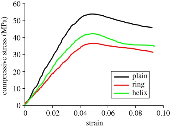
Representative stress–strain curves of different helicoidal fibre-reinforced composites under monotonic compression tests. (Online version in colour.)
(b). Fractographic characterization
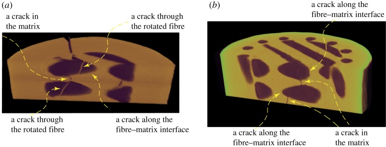
Crack propagations in helicoidal structures were first examined using the microCT technique. Two planes were selected to view the unsplit specimens after peak loads (figure 5). One plane was perpendicular to the cylindrical axis (the top view); the other plane was parallel to the cylindrical axis (the side view). From the side view, cracks could propagate through rotated fibres in helicoids, through matrices, or along fibre–matrix interfaces (figure 5a,b). In figure 5a, cracks first cut through helicoidal fibres, delaminated fibre–matrix interfaces and then cut through interlayer matrices. In figure 5b, cracks propagated along fibre–matrix interfaces and then through interlayer matrices. Generally, crack paths switched between intracracks (inside fibres or matrices) and interfacial cracks (along fibre–matrix interfaces). Further scanning electronic characterization confirmed that both delaminated fibre–matrix interfaces and broken helicoidal fibres existed in the fractured specimen (figure 6).
Figure 5.
MicroCT images of unsplit specimens after peak loads. (a) A plain specimen. (b) A helix-reinforced specimen. (Online version in colour.)
Figure 6.
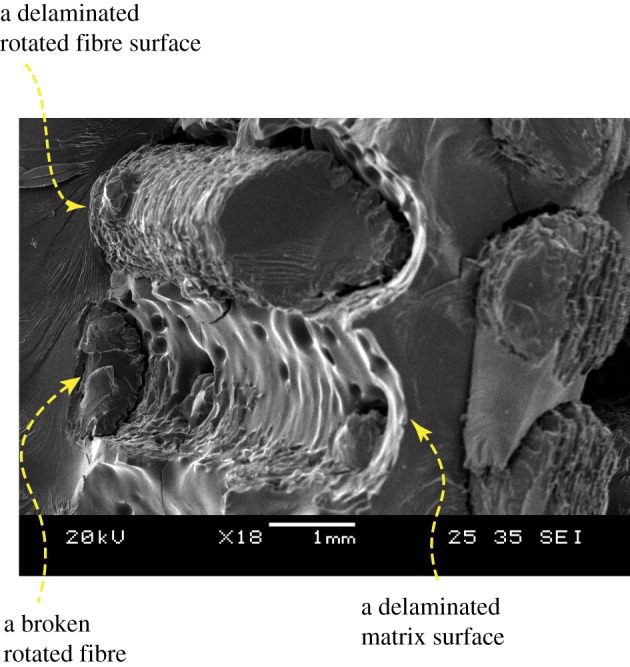
An SEM image of a fractured plain specimen, illustrating delaminated fibre–matrix interfaces and broken fibres. (Online version in colour.)
(c). Mathematical modelling of helicoidal fibre structures under compression
At the same fibre volume ratio, compression tests showed that helix reinforcements provided larger compressive resistance than ring reinforcements due to continuous shielding across rotated fibre layers. To elucidate the critical helicoidal architectures in resisting compression, finite-element models were created to investigate the effects of different factors, including modulus ratios between fibres and matrices, pitch angles of helix reinforcements, rotary angles between adjacent rotated fibre layers and numbers of helix reinforcements.
To evaluate the model performance, we compared finite-element predictions and experimental measurements in the elastic range, through which good agreement was obtained for different types of helicoidal specimens (figure 7). In the following sections, these models were used to study the effects of fibre architectures on the compressive resistance of helicoidal fibre structures in the elastic range.
Figure 7.
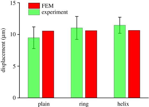
Comparison between finite-element predictions and experimental measurements in the elastic range. (Online version in colour.)
(i). Compressive stress distributions in helicoidal fibre structures
Two planes were selected to illustrate the stress distributions in helicoidal structures. The first plane was in the middle of two adjacent fibre layers, and the second plane was in the middle of the lower layer (figure 3b). The contours in the first plane illustrated stress distributions in interlayer matrices, while those in the second plane illustrated stress distributions in helicoids.
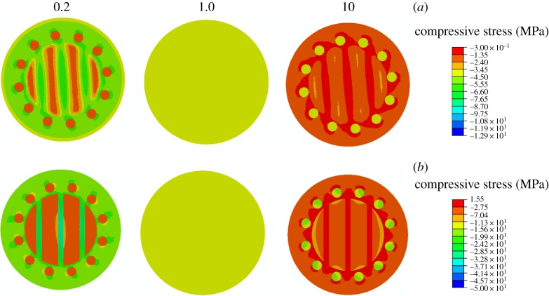
To study the effects of the fibre modulus on the compressive resistance, we varied the fibre–matrix ratios from 0.2 to 10, while maintaining the elastic modulus of the matrix at 1.3 GPa. Compressive stress contours of helicoidal structures at modulus ratios of 0.2, 1.0 and 10.0 are shown in figure 8. To better illustrate the contours, one scale bar is used for contours at ratios of 0.2 and 1.0, while the other scale bar is used for contours at a ratio of 10. When fibre–matrix modulus ratios were less than 1, higher compressive stresses were exhibited in matrices than those in fibres. When the fibre–matrix modulus ratio was 1, stress contours were uniform over cross sections, consistent with stress distributions of isotropic homogeneous materials under compression. When fibre–matrix modulus ratios were greater than 1, stresses in helix reinforcements were higher than those in matrices. These results demonstrated that helix reinforcements became more critical in resisting compression when fibre–matrix modulus ratios were large.
Figure 8.
Compressive stress distributions in helicoidal structures at different fibre–matrix modulus ratios of 0.2, 1 and 10. Scale bar (a) for contours at ratios of 0.2 and 1 and scale bar (b) for contours at a modulus ratio of 10. The top planes are contours of interlayer matrices, while the bottom planes are contours of rotated fibres. (Online version in colour.)
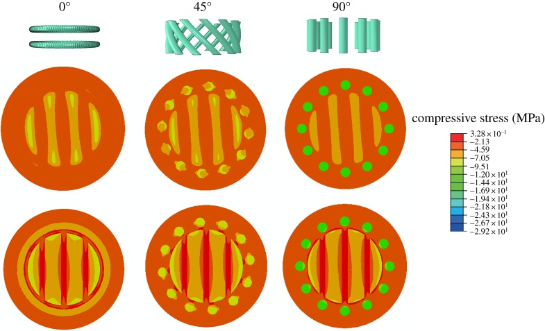
Finite-element models were also created to study the effects of helix pitch angles on the compressive resistance ranging from 0° to 90°. In these models, the fibre-matrix ratios were 5, and the fibre volume ratios were 0.30. The 0° model included ring reinforcements, while the 90° model included vertical reinforcements (figure 9). As the pitch angle increased, compressive stresses in the rotated helicoidal fibres varied slightly. However, compressive stresses in the helix reinforcements increased substantially. Ring reinforcements in the 0° model constrained the horizontal rotated fibres, but interlayer matrices were not reinforced sufficiently due to the lack of continuous shielding across rotated fibres (top planes). The 90° helix-reinforcement model was the most efficient at resisting compression, resulting in the highest stresses in the helix reinforcements.
Figure 9.
Compressive stresses in helicoidal structures with pitch angles of 0°, 45° and 90°. The top planes are contours of interlayer matrices, while the bottom planes are contours of rotated fibres. (Online version in colour.)
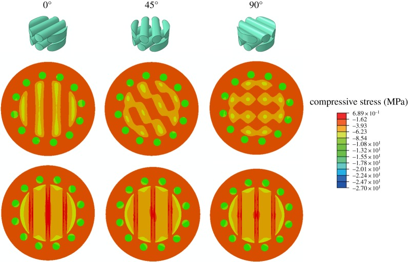
The interlayer rotary angles between adjacent horizontal fibres were crucial to the compressive resistance of helicoidal fibre structures. We created models with 12 helix reinforcements at pitch angles of 69°. The fibre–matrix modulus ratios were 5.0, and the fibre volume ratios were 0.30. Stress contours are shown for models with interlayer rotary angles of 0°, 45° and 90° (figure 10). On the bottom planes, stress distributions were almost the same. However, stress distributions in the interlayer matrices (top planes) changed from isolated strips to orthogonal networks as the interlayer rotary angle varied from 0° to 90°.
Figure 10.
Stress contours of helicoids with interlayer rotary angles of 0°, 45° and 90°. The top planes are contours of interlayer matrices, while the bottom planes are contours of rotated fibres. (Online version in colour.)
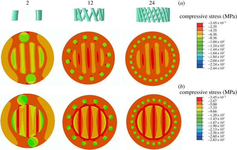
Mathematical modelling was also performed to study the effects of reinforcement numbers on the compressive resistance of helicoidal structures. Two to 24 helix reinforcements were placed around helicoids at pitch angles of 69°. The fibre–matrix modulus ratios were 5, and the fibre volume ratios were 0.30. To better illustrate stress contours, one scale bar was used for the two-helix model, whereas the other scale bar was used for the 12- and 24-helix models (figure 11). Stresses in the inner helicoidal cores were almost the same for specimens with different numbers of reinforcements on both the top and bottom planes, respectively. Also, higher stresses existed in helix reinforcements than those in rotated fibres, demonstrating that helix reinforcements were effective in resisting compression.
Figure 11.
Stress contours of helicoids with two-, 12- and 24-helix reinforcements. Scale bar (a) for the two-helix model and scale bar (b) for the 12- and 24-helix models. The top planes are contours of interlayer matrices, while the bottom planes are contours of rotated fibres. (Online version in colour.)
(ii). Two-dimensional trends of compressive resistance in helicoidal fibre structures
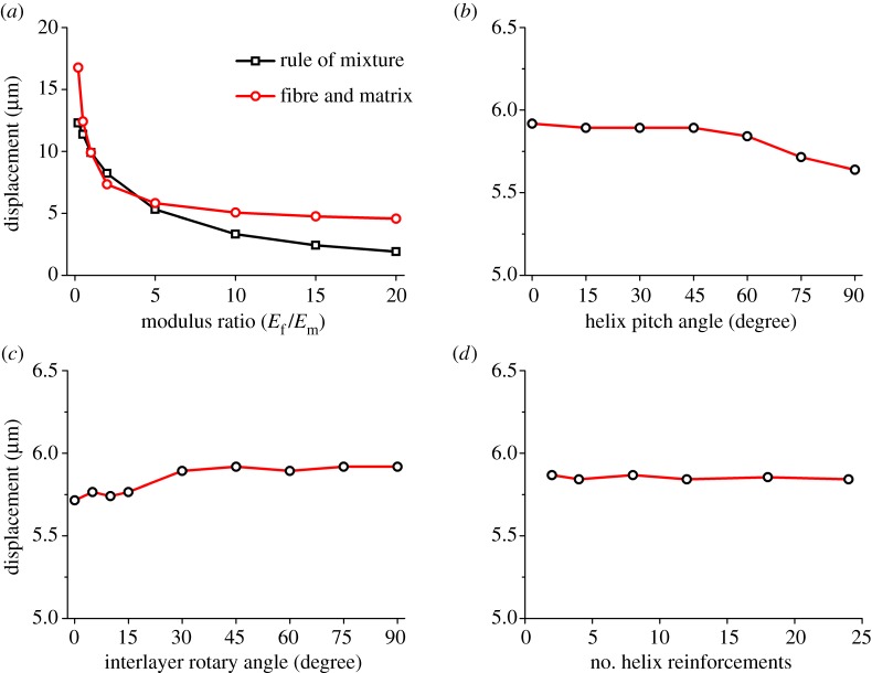
Detailed trends were further illustrated based on fibre–matrix ratios, pitch angles, interlayer rotary angles and helix numbers. First, displacements of helicoids were collected for models with modulus ratios from 0.1 to 20. In comparison, predictions of isotropic linear models based on the rule of mixtures [41,42] were included at corresponding ratios. The results (figure 12a) show that fibre–matrix modulus ratios affected the compressive resistance of helicoidal fibre structures. When fibre–matrix modulus ratios were less than unity, helicoidal structures exhibited larger displacements than isotropic models. This trend was reversed when modulus ratios varied from 1.0 to 5.0. However, when modulus ratios were greater than 5, helicoidal fibre structures exhibited larger displacements again.
Figure 12.
Two-dimensional displacement predictions of helicoids. (a) At modulus ratios ranging from 0.2 to 20 using both fibre-and-matrix and rule-of-mixture models. (b) At pitch angles ranging from 0° to 90°. (c) At interlayer rotary angles ranging from 0° to 90°. (d) With two to 24 helix reinforcements. (Online version in colour.)
Then, displacements under compression of helicoidal structures were examined by varying pitch angles from 0° to 90°. Figure 12b shows that smaller displacements occurred as the pitch angle increased, and helicoids with 90° vertical reinforcements exhibited the lowest displacement.
Variations in the interlayer rotary angle also affected the compressive resistance of helicoids (figure 12c). Small interlayer rotary angles resulted in a lower displacement of helicoidal fibre structures until the angle reached 15°. An increase in displacement occurred when the angle increased from 15° to 30°. After that, displacement plots became relatively flat. These results demonstrate that the reduction of overlapping areas between the rotated fibres resulted in larger displacements, which reduced the compressive resistance of helicoidal structures.
Displacements of helicoids with various helix reinforcements are shown in figure 12d. The central displacements under compression were not substantially affected by the numbers of helices given the same volume of helix reinforcements. This was because equal distances between the helix reinforcements and the cylindrical axis made these helicoids similar in compressive resistance.
(iii). Integrated study of the compressive resistance of helicoidal fibre structures
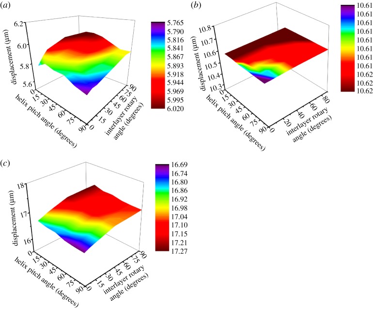
As illustrated in figures 8–11, stress contours in the helicoidal fibre cores and matrices vary according to the different fibre architectures and material properties. It should be noted that the occurrence of interfacial cracks (figures 5 and 6) also corresponds to the differences in stresses in the fibres and matrices. Further understanding of how these factors affect the compressive resistance of composite helicoidal fibre structures can be pursued by systematically exploring helicoids with different factors. An integrated study was performed to study the effects of multiple factors on the compressive resistance of helicoidal fibre structures in the elastic range, including pitch angles of helix reinforcements, interlayer rotary angles and fibre–matrix modulus ratios. In these models, the fibre volume ratios were 0.30. Interlayer rotary angles were 0°, 8°, 15°, 45°, 75° and 90°. Pitch angles were 15°, 30°, 45°, 60°, 75° and 90°. Three fibre–matrix modulus ratios were studied, i.e. 1 : 5, 1 : 1.3 and 5 : 1, while the elastic modulus of the matrix was 1.3 GPa.
Three-dimensional contours of displacements were summarized with respect to helix pitch angles, interlayer rotary angles and fibre–matrix modulus ratios (figure 13a–c). Among these plots, helicoidal fibre structures with stiffer fibres exhibited lower rotations (figure 13a) than those of soft fibres (figure 13b,c). Displacement variations existed in helicoidal structures for different interlayer and rotary angles (figure 13a,c). When the fibre–matrix modulus ratio was close to 1 (figure 13b), displacements were not sensitive to variations in helix pitch and interlayer rotary angles as expected. For all plots (figure 13a–c), lower displacements occurred in helicoids when the helix pitch angles were large, and the interlayer rotary angles were small. This was because helicoids with large pitch angles provided more vertical support to resist compression, while helicoids with small interlayer rotary angles generated more overlapped areas between rotated horizontal fibres.
Figure 13.
Three-dimensional displacement contours of helicoidal structures with respect to pitch and interlayer rotary angles at different modulus ratios: (a) 5 : 1, (b) 1 : 1.3 and (c) 1 : 5. (Online version in colour.)
In this work, we used an integrated experimental and modelling approach to reveal the compressive resistance of helicoidal fibre structures. The results are consistent with findings in prior studies. For example, our modelling results suggest that smaller interlayer rotary angles generated higher compressive resistance of helicoids, which is in agreement with the data trends obtained experimentally from Yang et al. [16]. Our results on other factors of the fibre architectures could also guide the creation of more bioinspired helicoids. In addition, we disclose the stress distributions in fibres and matrices of helicoids that have not been fully studied in the prior literature. Although the spiral crack patterns in helicoids have been reported [16,19,26,43,44], we reveal the alternating intra- and intercrack patterns between helicoidal layers. In the future, we will study the compressive failure of helicoidal fibre structures beyond the initial elastic range by combining experiments and mathematical modelling. Helicoidal structures will be optimized based on architectural and material constraints, and then be 3D-printed for experimental validation. Findings from these iterations will lead to the creation of high-performance bioinspired composites and structures.
4. Conclusion
Helicoidal fibre structures exist in many biological systems. In this work, an integrated experimental and numerical approach was used to study the compressive resistance of bioinspired helicoidal fibre structures. First, three types of helicoidal fibre-reinforced composites were created using 3D-printed helicoidal cores and polymeric matrices, including plain, ring-reinforced and helix-reinforced helicoids. Stress–strain curves of cylindrical composite specimens detailed the failure of helicoids under monotonic compression tests. Since matrices used in this study were slightly stronger than fibres, plain specimens with the fewest fibres exhibited the highest compressive strength. At the same fibre–volume ratio, helix-reinforced helicoids provided higher compressive resistance than ring-reinforced helicoids due to continuous shielding across rotated layers. Fractographic characterization showed that both cutting-through (intra-) and interfacial (inter-) cracks existed in failed helicoids. The alternating intra- and intercrack patterns in helicoids may effectively dissipate energy during crack propagations.
To reveal the critical fibre architecture in resisting compression, finite-element models were created to study the effects of various factors on the compressive resistance of helicoidal structures in the elastic range, including fibre–matrix modulus ratios, pitch angles of helix reinforcements, interlayer rotary angles between adjacent horizontal fibres and numbers of helix reinforcements. The results show that stress levels in helix reinforcements increased substantially at large fibre–matrix ratios. At the same fibre–volume ratio, helicoids with large pitch angles and small interlayer rotary angles exhibited higher compressive resistance, while the compressive resistance was not substantially affected by numbers of helix reinforcements. This was because vertical helix reinforcements and extensively overlapped fibres at small rotary angles generated more efficient structures to resist compression. Based on these findings, the fibre–matrix modulus ratios and pitch angles of helix reinforcements are most essential to the compressive resistance of helicoidal fibre-reinforced composites. It is expected that larger fibre–matrix ratios (more than 10) and larger helix pitch angles (close to 90°) could lead to more compression-resistant helicoidal fibre structures. The authors also expect to extend the study of helicoidal fibre structures beyond the initial elastic stage, and develop extended models to elucidate the entire failure of helicoids in the future.
Acknowledgements
The authors would like to thank Professor Mandar Dewoolkar for the access to the microCT equipment, obtained through the Major Research Instrumentation Program from the National Science Foundation (grant no. 1429252). Appreciation is also extended to the UVM microscopy imaging center for the assistance with image characterization.
Data accessibility
The experimental and modelling data are available at https://drive.google.com/open?id=0B_OlEMqAMr29MlFONFpPWUhXSDg.
Authors' contributions
T.T. and B.R. performed the experiments, conducted the modelling and wrote the paper.
Competing interests
The authors have no competing interests.
Funding
This work is supported by the College of Engineering and Mathematical Sciences at the University of Vermont (UVM), the Vermont NASA EPSCoR (grant no. NNX13AB35A), the UVM clean energy fund (grant no.~028613) and the Vermont Venture Innovation Fund (grant no. 031365).
References
- 1.Neville AC. 1993. Biology of fibrous composites: development beyond the cell membrane. Cambridge, UK: Cambridge University Press. [Google Scholar]
- 2.Meyers MA, McKittrick J, Chen PY. 2013. Structural biological materials: critical mechanics-materials connections. Science 339, 773–779. (doi:10.1126/science.1220854) [DOI] [PubMed] [Google Scholar]
- 3.Wegst UG, Bai H, Saiz E, Tomsia AP, Ritchie RO. 2015. Bioinspired structural materials. Nat. Mater. 14, 23–36. (doi:10.1038/nmat4089) [DOI] [PubMed] [Google Scholar]
- 4.Naleway SE, Porter MM, McKittrick J, Meyers MA. 2015. Structural design elements in biological materials: application to bioinspiration. Adv. Mater. 27, 5455–5476. (doi:10.1002/adma.201502403) [DOI] [PubMed] [Google Scholar]
- 5.Raabe D, Al-Sawalmih A, Yi S, Fabritius H. 2007. Preferred crystallographic texture of α-chitin as a microscopic and macroscopic design principle of the exoskeleton of the lobster Homarus americanus. Acta. Biomater. 3, 882–895. (doi:10.1016/j.actbio.2007.04.006) [DOI] [PubMed] [Google Scholar]
- 6.Nikolov S, Petrov M, Lymperakis L, Friák M, Sachs C, Fabritius HO, Raabe D, Neugebauer J. 2010. Revealing the design principles of high-performance biological composites using ab initio and multiscale simulations: the example of lobster cuticle. Adv. Mater. 22, 519–526. (doi:10.1002/adma.200902019) [DOI] [PubMed] [Google Scholar]
- 7.Weaver JC, et al. 2012. The stomatopod dactyl club: a formidable damage-tolerant biological hammer. Science 336, 1275–1280. (doi:10.1126/science.1218764) [DOI] [PubMed] [Google Scholar]
- 8.Amini S, Tadayon M, Idapalapati S, Miserez A. 2015. The role of quasi-plasticity in the extreme contact damage tolerance of the stomatopod dactyl club. Nat. Mater. 14, 943–950. (doi:10.1038/nmat4309) [DOI] [PubMed] [Google Scholar]
- 9.Chen PY, Lin AYM, McKittrick J, Meyers MA. 2008. Structure and mechanical properties of crab exoskeletons. Acta. Biomater. 4, 587–596. (doi:10.1016/j.actbio.2007.12.010) [DOI] [PubMed] [Google Scholar]
- 10.Chen PY, McKittrick J, Meyers MA. 2012. Biological materials: functional adaptations and bioinspired designs. Prog. Mater. Sci. 57, 1492–1704. (doi:10.1016/j.pmatsci.2012.03.001) [Google Scholar]
- 11.Currey JD. 2002. Bones: structure and mechanics. Princeton, NJ: Princeton University Press. [Google Scholar]
- 12.Wagermaier W, Gupta H, Gourrier A, Burghammer M, Roschger P, Fratzl P. 2006. Spiral twisting of fiber orientation inside bone lamellae. Biointerphases 1, 1–5. (doi:10.1116/1.2178386) [DOI] [PubMed] [Google Scholar]
- 13.Tan T, Rahbar N, Allameh S, Kwofie S, Dissmore D, Ghavami K, Soboyejo W. 2011. Mechanical properties of functionally graded hierarchical bamboo structures. Acta. Biomater. 7, 3796–3803. (doi:10.1016/j.actbio.2011.06.008) [DOI] [PubMed] [Google Scholar]
- 14.Carlquist S. 2013. Comparative wood anatomy: systematic, ecological, and evolutionary aspects of dicotyledon wood. New York, NY: Springer Press. [Google Scholar]
- 15.Meyers MA, Lin AY, Seki Y, Chen PY, Kad BK, Bodde S. 2006. Structural biological composites: an overview. JOM 58, 35–41. (doi:10.1007/s11837-006-0138-1) [Google Scholar]
- 16.Yang Y, Chen Z, Song X, Zhang Z, Zhang J, Shung KK, Zhou Q, Chen Y. 2017. Biomimetic anisotropic reinforcement architectures by electrically assisted nanocomposite 3D printing. Adv. Mater. 29, 1605750 (doi:10.1002/adma.201605750) [DOI] [PMC free article] [PubMed] [Google Scholar]
- 17.Makris EA, Hadidi P, Athanasiou KA. 2011. The knee meniscus: structure–function, pathophysiology, current repair techniques, and prospects for regeneration. Biomaterials 32, 7411–7431. (doi:10.1016/j.biomaterials.2011.06.037) [DOI] [PMC free article] [PubMed] [Google Scholar]
- 18.Mitov M. 2017. Cholesteric liquid crystals in living matter. Soft Matter 13, 4176–4209. (doi:10.1039/c7sm00384f) [DOI] [PubMed] [Google Scholar]
- 19.Milliron G. 2012. Lightweight impact-resistant composite materials: lessons from mantis shrimp. PhD Thesis, University of California Riverside, Riverside, CA, USA. [Google Scholar]
- 20.Dimas LS, Bratzel GH, Eylon I, Buehler MJ. 2013. Tough composites inspired by mineralized natural materials: computation, 3D printing, and testing. Adv. Funct. Mater. 23, 4629–4638. (doi:10.1002/adfm.201300215) [Google Scholar]
- 21.Nganga S, et al. 2014. Inkjet printing of Chitlac-nanosilver—a method to create functional coatings for non-metallic bone implants. Biofabrication 6, 041001 (doi:10.1088/1758-5082/6/4/041001) [DOI] [PubMed] [Google Scholar]
- 22.Ribbans B, Li YJ, Tan T. 2016. A bioinspired study on the interlaminar shear resistance of helicoidal fiber structures. J. Mech. Behav. Biomed. 56, 57–67. (doi:10.1016/j.jmbbm.2015.11.004) [DOI] [PubMed] [Google Scholar]
- 23.Gu G, Su I, Sharma S, Voros J, Qin Z, Buehler MJ. 2016. 3D-printing of bio-inspired composites. J. Biomech. Eng. 138, 021006 (doi:10.1115/1.4032423) [DOI] [PMC free article] [PubMed] [Google Scholar]
- 24.Studart AR. 2016. Additive manufacturing of biologically-inspired materials. Chem. Soc. Rev. 45, 359–376. (doi:10.1039/C5CS00836K) [DOI] [PubMed] [Google Scholar]
- 25.Grunenfelder L, et al. 2014. Bio-inspired impact-resistant composites. Acta. Biomater. 10, 3997–4008. (doi:10.1016/j.actbio.2014.03.022) [DOI] [PubMed] [Google Scholar]
- 26.Shang J, Ngern NH, Tan VB. 2016. Crustacean-inspired helicoidal laminates. Compos. Sci. Technol. 128, 222–232. (doi:10.1016/j.compscitech.2016.04.007) [Google Scholar]
- 27.Yaraghi NA, et al. 2016. Biocomposites: a sinusoidally architected helicoidal biocomposite. Adv. Mater. 28, 6835–6844. (doi:10.1002/adma.201600786) [DOI] [PubMed] [Google Scholar]
- 28.Ginzburg D, Pinto F, Iervolino O, Meo M. 2017. Damage tolerance of bio-inspired helicoidal composites under low velocity impact. Compos. Struct. 161, 187–203. (doi:10.1016/j.compstruct.2016.10.097) [Google Scholar]
- 29.Chen B, Peng X, Cai C, Niu H, Wu X. 2006. Helicoidal microstructure of Scarabaei cuticle and biomimetic research. Mater. Sci. Eng. A 423, 237–242. (doi:10.1016/j.msea.2005.11.069) [Google Scholar]
- 30.Marklund E, Varna J. 2009. Modeling the effect of helical fiber structure on wood fiber composite elastic properties. Appl. Compos. Mater. 16, 245–262. (doi:10.1007/s10443-009-9091-9) [Google Scholar]
- 31.Wright J, Sloan M, Evans K. 2010. Tensile properties of helical auxetic structures: a numerical study. J. Appl. Phys. 108, 044905 (doi:10.1063/1.3465378) [Google Scholar]
- 32.Sloan M, Wright J, Evans K. 2011. The helical auxetic yarn—a novel structure for composites and textiles; geometry, manufacture and mechanical properties. Mech. Mater. 43, 476–486. (doi:10.1016/j.mechmat.2011.05.003) [Google Scholar]
- 33.Davallo M, Pasdar H, Mohseni M. 2010. Mechanical properties of unsaturated polyester resin. Int. J. ChemTech. Res. 2, 2113–2117. [Google Scholar]
- 34.Dostal CA. 1987. Engineered materials handbook. Boca Raton, FL: CRC Press. [Google Scholar]
- 35.Bagherpour S. 2012. Fibre reinforced polyester composites. In Polyester (ed. Saleh HEDM.), pp. 135–166. Rijeka, Croatia: InTech Open Access Publisher. [Google Scholar]
- 36.Vaidya UK.2015. Composite materials and structures—education module. See http://www.angelfire.com/ma/ameyavaidya/ .
- 37.Stratasys. 2014. PolyJet materials data sheet. See http://www.stratasys.com/materials/material-safety-data-sheets/polyjet.
- 38.Aly MF, Goda I, Hassan GA. 2010. Experimental investigation of the dynamic characteristics of laminated composite beams. Int. J. Mech. Mechatronics Eng. 10, 59–67. (doi:10.1.1.207.5914) [Google Scholar]
- 39.Ribbans B. 2015. Bioinspired study on the mechanical performance of helicoidal fiber structures. Masters Thesis, University of Vermont, Burlington, VT, USA. [Google Scholar]
- 40.Dassault Systèmes. 2017. ABAQUS analysis user's manual. Providence, RI: Dassault Systèmes. [Google Scholar]
- 41.Hull D, Clyne T. 1996. An introduction to composite materials. Cambridge, UK: Cambridge University Press. [Google Scholar]
- 42.Mallick PK. 2007. Fiber-reinforced composites: materials, manufacturing, and design. Boca Raton, FL: CRC press. [Google Scholar]
- 43.Faber KT, Evans AG. 1983. Crack deflection processes—I. Theory. Acta. Metall. 31, 565–576. (doi:10.1016/0001-6160(83)90046-9) [Google Scholar]
- 44.Suksangpanya N, Yaraghi NA, Kisailus D, Zavattieri P. In press. Twisting cracks in Bouligand structures. J. Mech. Behav. Biomed. (doi:10.1016/j.jmbbm.2017.06.010) [DOI] [PubMed] [Google Scholar]
Associated Data
This section collects any data citations, data availability statements, or supplementary materials included in this article.
Data Availability Statement
The experimental and modelling data are available at https://drive.google.com/open?id=0B_OlEMqAMr29MlFONFpPWUhXSDg.


