Abstract
Purpose
To develop a method to evaluate the positional variations of multiple off-axial targets for a single isocenter stereotactic radiosurgery (SRS) treatment in Novalis Tx linac system.
Method and Materials: Five metallic ball bearing (BB) markers were placed sparsely in 3D off-axial locations (non-coplanar) inside a skull phantom as the representatives of multiple targets mimicking multiple brain metastases. The locations of the BB markers were carefully chosen to minimize overlapping of each other in a portal imaging detector plane. The skull phantom was immobilized by a frameless mask and CT scanned with a BrainLab Head&Neck Localizer using a GE Optima multi-detector CT (MDCT) scanner. The CT images were exported to iPlan treatment planning software and a multiple target PTV was drawn by combining all the contours of the BB markers. The margin of the MLC opening was selected as 3 mm expansion outward. Four non-coplanar arc beams were placed to generate a single isocenter SRS plan to treat the PTV. The skull phantom was localized to the treatment position using ExacTrac 6D Patient Positioning system. The four dynamic conformal arc beams were delivered using Novalis Tx system with portal imaging acquisition mode per 10% temporal resolution. The locations of the BB markers were visualized and analyzed with respect to the MLC aperture in the treatment plan similar to the Winston-Lutz (WL) test.
Results
All the BB markers were clearly identified inside the MLC openings. The total positional errors for the MLC aperture were 0.61 ± 0.2 mm along the rotational path of the four arcs.
Conclusion
This study verified that the spatial deviations of multiple off-axial targets for a single isocenter SRS treatment plan is within sub-millimeter range in Novalis Tx linac system. Accompanied with the WL test, this simple test will quality-assure the spatial accuracies of the isocenter as well as the positions of multiple off-axial targets for the SRS treatment using a single isocenter multiple target treatment plan.
Keywords: multiple brain metastases, SRS, Novalis Tx, ExacTrac, off-axis, non-coplanar, Winston-Lutz
1. INTRODUCTION
Brain metastases are tumors which originate from other sites in the patient body. These tumors are a common complication of systemic cancer which occurs in about 30% of cancer patients [1]. They have a poor prognosis for cure; the typical survival time of a patient with brain metastases is from several months to a year. In the United States, approximately 170,000 cancer patients will develop brain metastases each year [2]. Previous clinical studies have shown that about half of brain metastases will be multiple brain metastases which have more than one lesion spread in the brain [3-5].
Historically, whole-brain radiation therapy (WBRT) has been a standard palliative care for the multiple brain metastases [6]. However, recent studies found that WBRT with stereotactic radiosurgery (SRS) boost can achieve better local control and median survival time [7] or only better local control with no differences in overall survival [8]. From these facts, the role of SRS treatment became more important in the brain metastases treatment these days.
It is challenging to treat multiple brain metastases with SRS technique. First, it is not appropriate to apply the technique to large size metastases due to the high normal tissue toxicities. Therefore, careful patient selection is necessary based on the eligibility test for SRS – size, shape, location, neurocognitive function, etc. Second, there is a radiation beam overlapping issue when conventional three-dimensional (3D) multiple isocenter non-coplanar dynamic conformal arc technique is employed. For example, if five dynamic conformal arc beams are employed per each metastasis for three lesions, fifteen arc beams will pass through the whole brain with different focusing isocenters which makes it difficult to avoid the beam overlapping. Third, treatment delivery for these 3D non-coplanar dynamic arc beams takes significant amount of time due to the patient immobilization and gantry-couch rotations; because of complicated couch-gantry angle combination, multi-isocenter SRS treatment usually requires pre-treatment collision check and it could take over an hour to treat a single SRS patient. In the previous study, it was shown that the single isocenter treatment delivery is more efficient than the multiple isocenter treatment [9].
Volumetric Modulated Arc Therapy (VMAT) technique has emerged improving the radiation treatment delivery as well as providing the equivalent quality of treatment plan compared to IMRT and Helical TomoTherapy plans by utilizing an arc-type intensity modulated cone beam delivery [10-12]. For this benefit of treatment delivery, VMAT technique has promptly been applied to treat various sites such as prostate, head & neck, lung and even breast [13-15]. However, it has not been frequently used in SRS treatment due to the reason that SRS is typically used to treat a small and spherical shape of target where intensity modulation is not necessary for the normal tissue toxicity.
Recently, there are several studies performed in applying the VMAT technique [16-17] or dynamic conformal arc method [18] to treat the multiple brain metastases using a single isocenter approach. These techniques were found to produce a clinically acceptable treatment plan while reducing the treatment delivery time [18-20]. However, there is no quality assurance (QA) method to verify whether the multi-leaf collimators (MLC) are correctly opening at the off-axial positions where the multiple brain metastases are located. Because SRS is designed to deliver the large amount of radiation dose in a few fractions unlike conventional radiation therapy, this positional verification is important to assure the patient safety as well as the treatment quality.
To assure accurate treatment deliveries for SRS plans, historically Winston-Lutz (WL) test has been used to guarantee that the radiation isocenter matches to the mechanical isocenter within sub-millimeter accuracy [21-22]. The WL test has been sufficient to validate the targeting accuracy for a single isocentric target because the conventional SRS plan normally has the isocenter placed at the center of the single target. But, for the treatment of brain metatheses sparsely located in multiple positions using a VMAT technique with a single isocenter treatment plan, the WL test may not be sufficient to assure the targeting accuracy because it only verifies the isocentricity of the linac system and not the positional accuracy for the off-axial targets. Again, there is currently no standard QA method for the multi-target single isocenter treatment plan to check the targeting accuracy of multiple PTVs which are not located at the isocenter. In this study, we investigated a simple method to evaluate the spatial variations of multiple off-axial targets for a single isocenter SRS treatment plan in Novalis Tx linear accelerator (linac) system (Varian Medical System, USA; BrainLab AG, Germany) that can be a part of QA procedure for the specific treatments.
2. METHOD AND MATERIALS
We employed a plastic skull phantom to represent a brain metastases patient in this study. As shown in Figure 1 (a), this phantom originally has multiple 3D geometric shapes (cone, sphere, cylinder and square bar) on the plastic base plate typically used for the verification of the MLC shapes as well as isocenter verification [23]. This phantom was modified for the purpose of this study. First, the base plate was replaced to a new base plate in order to mount virtual brain metastases in 3D space. By creating a new base plate, we were able to preserve the original plate which still can be used for the aforementioned original function of the phantom. Multiple screw holes were drilled on the new plate with the distance of 2.8 cm and nylon bolts (size: 0.25 inch x 2 inch, 64) were screwed on the plate. By using this screw design, one can adjust the heights of the bolts head where metallic ball bearings (BB) are attached as the representatives of multiple targets mimicking multiple brain metastases.
Figure 1.
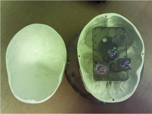
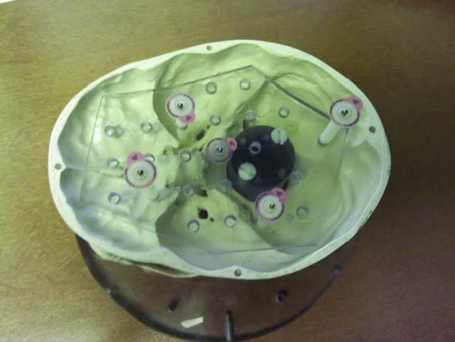
(a) A original skull phantom with multiple 3D geometric shapes (cone, sphere, cylinder and square bar) on the plastic base plate typically used for the verification of the MLC shapes as well as isocenter verification, (b) A skull phantom with five metallic BBs which represent the multiple target locations placed in 3D space.
Five metallic BB markers (steel, 2 mm in diameter) were placed on the head of the nylon bolts sparsely in 3D off-axial locations (non-coplanar) inside a skull phantom (See Figure 1 (b)). Metallic BB markers were chosen in order to visualize them on the portal images acquired by electronic portal image device (EPID, PortalVision, Varian Medical System, USA). The locations of the BB markers were carefully chosen to minimize overlapping of each other in the port imaging detector plane. It should be mentioned that the positions of the BB markers relative to the isocenter were not estimated due to the technical difficulties in physically measuring the distances between the BB markers and the isocenter in 3D space for our in-house made phantom. Rather than defining the position of the BB markers in the 3D space, we chose to estimate the spatial shifts of the BB markers in a projected 2D space using the EPID device.
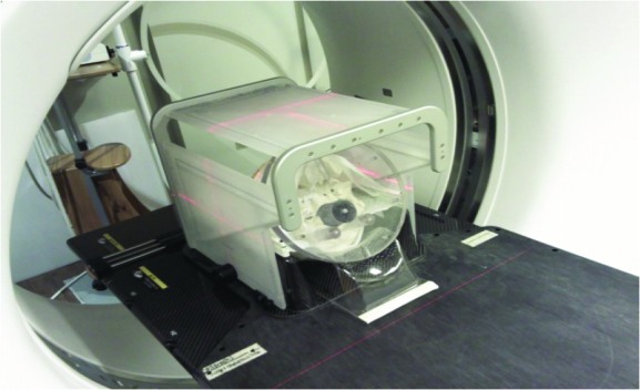
Using the modified skull phantom, we performed an “End-to-End Test” for a single isocenter VMAT SRS treatment in multiple brain metastases. In the test, the skull phantom was treated as same as a human patient. In the first step, the phantom was immobilized by a BrainLab thermoplastic mask in a CT simulation room and CT scanned with a BrainLab Head&Neck Localizer using an SRS head scan protocol (slice thickness: 1 mm) in a GE Optima multi-detector computed tomography (MDCT) scanner (See Figure 2). Then, the scanned CT images were exported to SRS treatment planning software (iPlan v 4.1, BrainLab AG, Germany). In iPlan RT Image software, the CT images were localized using the Head&Neck Localizer geometry and a multiple target PTV was drawn by combining all the contours of the BBs. The margin of the MLC opening was selected as 3 mm expansion outward.
Figure 2.
CT scanning process with a BrainLab mask and Head & Neck localizer. The Localizer was used for the purpose of 3D stereotactic localization in the treatment planning and delivery.
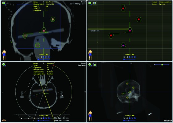
After the contouring of the target, a single isocenter 3D Dynamic Conformal Arc Treatment (3D-DCAT) plan was created in IPlan RT Dose software (See Figure 3). Four non-coplanar arc beams were placed to generate the single isocenter SRS plan to treat the PTV with the prescription dose of 500 cGy avoiding the saturation of EPID imaging. The photon beam energy of 6X-SRS mode in Novalis Tx linac with HD MLC (Varian Medical System, USA) was used in the treatment planning. Table 1 shows the four dynamic conformal arc beam parameters used in this study. Note that the generated treatment plan in this study is not a VMAT plan but a 3D-DCAT for several reasons. First, the size of the multiple off-axis targets was too small and it was not necessary to modulate the intensity of the beam. Second, the purpose of the single isocenter treatment planning in this study was to evaluate the geometrical accuracy of the MLC openings versus off-axial locations, not dosimetry verifications. Third, it is challenging to evaluate the geometric accuracy of irregular MLC apertures in a VMAT plan. Therefore, the single isocenter 3D-DCAT plan was suitable for the intention of this study.
Figure 3.
Non-coplanar dynamic conformal arc SRS treatment planning performed in iPlan RT Dose software. Note that five BB markers, which represent the multiple brain metastases sparsely spread, are contoured as targets in the planning system.
Table 1.
A single isocenter 3D-DCAT plan beam parameters used in this study. Note that arc range is 140 degree and couch angle of 20 degree is employed for non-coplanar delivery.
| Gantry Start (deg) | Gantry End (deg) | Collimator Angle (deg) | Couch Angle (deg) | |
| Arc #1 | 200 | 340 | 0 | 0 |
| Arc #2 | 200 | 340 | 330 | 20 |
| Arc #3 | 20 | 160 | 0 | 0 |
| Arc #4 | 20 | 160 | 5 | 340 |
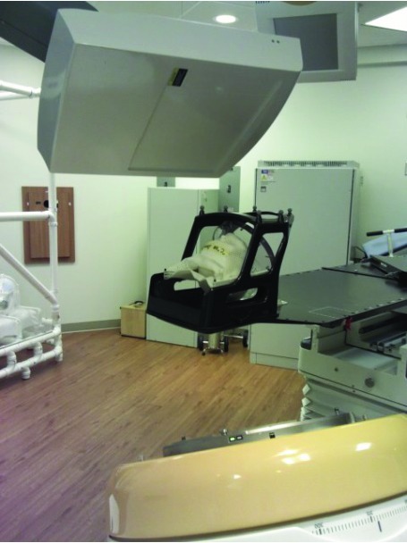
The 3D-DCAT plan created in the iPlan system was exported to Eclipse/Aria treatment planning/verification system (Varian Medical System, USA) for the treatment delivery. As can be seen in Figure 4, the modified skull phantom was placed on the BrainLab head & neck extension of the ExacTrac 6D robotic couch system (ExacTrac v 5.5.6, BrainLab AG, Germany) immobilized with the thermoplastic mask. BrainLab Frameless Radiosurgery Positioning Array was attached to utilize the two-dimensional (2D) stereoscopic infra-red (IR) localization system for initial phantom setup. Then, 2D stereoscopic x-ray images were acquired to fine-tune the setup. The four dynamic conformal arc beams were delivered using the Novalis Tx system with EPID portal imaging acquisition mode per 10% temporal resolution. That is, ten snapshot portal images were acquired per arc. The spatial resolution of the portal images was 0.26 mm/pixel at the isocenter [24].
Figure 4.
SRS treatment plan delivery with real-time portal imaging acquisition mode with EPID in Novalis Tx linac system. Note that BrainLab Frameless Radiosurgery Positioning Array was used for the initial phantom setup.
The locations of the BB markers in the acquired portal images were visualized and analyzed with respect to the MLC aperture in the treatment plan similar to the WL test. However, because the MLC opening in this study is variable per control point of the arc beams (not same as a single designated square or a circular shape used in the WL test), a different approach was introduced for the analysis of geometric discrepancies between treatment plan beam’s eye view (BEV) image and the portal images. First, the individual MLC aperture in the portal image was registered to the treatment plan BEV image using affine image registration method. Then the central distance of the corresponding BB markers between the treatment BEV image and the portal image was measured using MATLAB image processing toolbox software (Mathworks, USA) and analyzed.
3. RESULTS
As shown in Figure 5, the MLC aperture in the portal image was found to be virtually identical to that of treatment plan BEV image. Additionally all the BB markers were clearly identified inside the MLC openings on the EPID portal images. Note that there were some abutting MLC leakages at the mid line in the portal image. This leakage represents the dosimetric leaf gap which is ~0.7 mm/leaf bank for the Varian HD MLC.
Figure 5.
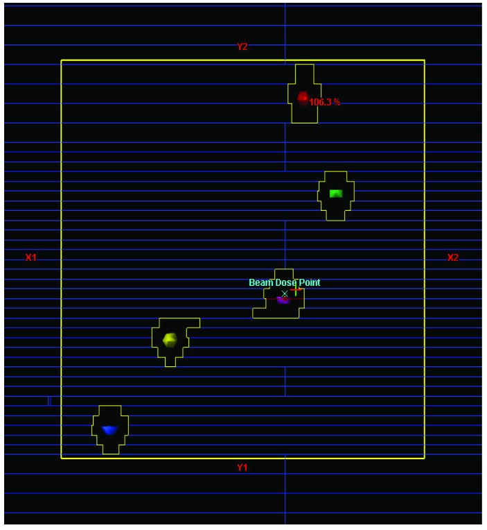
Snapshots of (a) the treatment plan beam’s eye view image in the Eclipse treatment planning system (each colored sphere in the BEV represents an individual target.) and (b) the portal image acquired from the SRS arc treatment beam deliveries (white small dots within the MLC openings represent the metallic BB markers.) Note that the all the five BBs are well visualized in the portal image.
The positional variations of the individual BB markers are shown in Table 2; mean and standard deviation values were evaluated from the EPID portal images. It was found that the average position differences ± standard deviation were 0.56 ± 0. 06 mm, 0.63 ± 0.04 mm, 0.52 ± 0.09 mm, 0.64 ± 0.11 mm, and 0.71 ± 0.10 mm from the target #1 to target #5 respectively. Total average positional deviation was 0.61 ± 0.20 mm along the rotational path of the four dynamic conformal arcs used in this study. The total mean and standard deviations for each dynamic conformal arc as well as each target were comparable each other. Note that the positional mean was calculated with all positive numbers, that is, the direction of the offset in each image was not taken into account. In addition, it should be mentioned that the positional variations were evaluated from the individual BB positions relative to the MLC aperture shapes on a “2D planar space” not based on the absolute 3D geometrical positions. Therefore, farthest targets may not show the largest deviations.
Table 2.
Mean and standard deviation of BB markers positional variations for the 3D-DCAT beams. Note that Targets were numbered as positional sequence. e.g. Target #1 and #5 represent the farthest targets from the isocenter located in the Y2 direction of linac collimator coordinate system. (Positional mean was calculated with all positive numbers, i.e. the direction of the offset in each image was not taken into account.)
| Positional Difference: Mean (mm) ± Standard Deviation (mm) | ||||||
| Target #1 | Target #2 | Target #3 | Target #4 | Target #5 | Total | |
| Arc #1 | 0.42 ± 0.22 | 0.58 ± 0.17 | 0.51 ± 0.16 | 0.72 ± 0.12 | 0.77 ± 0.06 | 0.60 ± 0.20 |
| Arc #2 | 0.67 ± 0.19 | 0.73 ± 0.08 | 0.38 ± 0.27 | 0.49 ± 0.31 | 0.54 ± 0.29 | 0.56 ± 0.27 |
| Arc #3 | 0.47 ± 0.21 | 0.66 ± 0.12 | 0.66 ± 0.07 | 0.64 ± 0.10 | 0.78 ± 0.11 | 0.64 ± 0.16 |
| Arc #4 | 0.68 ± 0.09 | 0.57 ± 0.09 | 0.55 ± 0.12 | 0.73 ± 0.08 | 0.78 ± 0.17 | 0.66 ± 0.14 |
| Total | 0.56 ± 0.06 | 0.63 ± 0.04 | 0.52 ± 0.09 | 0.64 ± 0.11 | 0.71 ± 0.10 | 0.61 ± 0.20 |
4. DISCUSSIONS
There are several studies performed to evaluate the phantom or patient setup uncertainties of ExacTrac 6D patient positioning system [25-32]. Yan et al performed a phantom study on the positioning accuracy of the ExacTrac/Novalis Body system and found that the average positioning accuracy was 1 mm [30]. Jin et al also investigated the target localization accuracy of the ExacTrac system and reported the average accuracy of ±0.6 mm [31-32]. Most phantom studies used anthropomorphic phantoms which contain several hidden markers inside the phantoms [25-26, 30- 32]. They basically performed the ‘hidden target test’ to evaluate the localization accuracy of the ExacTrac couch system and reported the localization accuracy overall less than 1 mm. Other studies analyzed their recorded ExacTrac couch shift data from patient pre/after treatment setup parameters and compared them with the regular 4D patient setup parameters (3 translations + couch rotation) [27-29]. The results indicated that the overall clinical patient setup accuracy using ExacTrac system was less than 2 mm.
Although the results of the previous studies are quite useful, there is a limitation on them; all of these studies evaluated the phantom/patient setup uncertainties focused on “only” ExacTrac robotic couch system not the whole Novalis linac treatment delivery system. The targeting accuracy in the patient treatment is correlated to not only the setup accuracy of the ExacTrac 6D system but also multiple components from CT simulation to treatment beam delivery – (1) CT slice thickness, (2) linac gantry stability (gantry sag), (3) MLC leaf positioning accuracy, (4) mechanical vs radiation isocentricity. Therefore, it is better to investigate the positioning deviation of the whole linac system by performing an End-to-End test in order to exactly understand the limitation of the whole system. The motivation of this study started from the questions how accurately the Novalis Tx linac system can deliver the radiation to the off-axially located targets which are away from the isocenter including all the above systematic uncertainties and how to quality assure the treatment deliveries of the off-axial targets.
In this study, we presented a simple QA method to verify the multiple off-axial target positions for a single isocenter SRS treatment in Novalis Tx linac system using an in-house made skull phantom. We also estimated the spatial variations of the multiple off-axial targets and found to be ~0.6 mm on average. There are several possibilities that cause the deviations (1) CT slice thickness of 1 mm could produce the maximum positional error of 0.5 mm for the BB markers in the CT scan, (2) maximum 1 mm localization error of the ExacTrac 6D system (3) linac gantry could sag at the range of 0.7 – 1 mm in maximum [33], and (4) spatial resolution of portal imager at the isocenter (0.26 mm/ pixel) [24]. It should be mentioned that sensitivities of the above causes were not thoroughly investigated. It is beyond the scope of this study and left for the future.
Although we only investigated for the single isocenter multiple targets using a skull phantom in this study, the application can be extended to other anatomical phantoms. That is, a torso or abdominal phantom can be manufactured embedded with multiple metallic markers and used with the same purpose of this study for the body sites. However, it should be mentioned that the application with the body phantom has a technical limitation in using non-coplanar arc beams due to the limited couch/patient-gantry clearance; skull phantom is advantageous in applying this study’s method because of its large clearance in couch/patient-gantry collision owing to its distal location in the body as well as smaller size. However, the couch collision issue can be resolved by limiting couch rotation as well as arc beam range (e.g. half arc).
Although the original purpose of the study was to evaluate the positional deviations of the off-axial target positions for a single isocenter SRS treatment in Novalis Tx linac system that can be considered as a part of machine quality assurance (QA), the method used in this study can be extended to the patient specific QA of multiple brain metastases for 3D geometric and dosimetric evaluation if an effective mapping method can be developed to accurately correlate the patient tumor positions to the BB markers in the phantom. For this 3D dosimetric QA application, an alternative approach could be developed to use a 3D printer to generate the patient geometry with 3D gel dosimeters in the future.
5. CONCLUSION
This study found that all the BB markers were clearly identified inside the MLC openings on the EPID portal images for a single isocenter SRS treatment delivery. The positional variations of the off-axial targets for a single isocenter SRS treatment using Novalis Tx linac system were overall less than 1 mm along the rotational path of the four dynamic conformal arc beams.
This study demonstrated that the Novalis TX linac system can precisely localize the multiple target PTV in 3D space with sub-millimeter accuracy. Accompanied with the WL test, this simple test will quality-assure the spatial accuracies of the isocenter and the locations of multiple targets for the SRS treatment using a single isocenter multiple target treatment plan.
6. ACKNOWLEDGEMENTS
This study was presented at general poster session in the AAPM Annual Meeting held in Austin TX 2014.
REFERENCES
- Wen PY, Black PM, Loeffler JS. Metastatic brain cancer. In: DeVita VT, Hellman S, Rosenberg SA, eds. Cancer, principles & practice of oncology. 6th ed. Philadelphia, PA: Lippincott Williams & Wilkins; 2001:2655-2670. [Google Scholar]
- 2. Posner JB. Management of brain metastases. Rev Neurol (Paris). 1992;148 (6-7):477-487. [PubMed] [Google Scholar]
- 3. Nussbaum ES, Djalilian HR, Cho KH, Hall WA. Brain metastases. Histology, multiplicity, surgery, and survival. Cancer. 1996;78(8):1781-1788. [PubMed] [Google Scholar]
- 4. Delattre JY, Krol G, Thaler HT, Posner JB. Distribution of brain metastases. Arch Neurol. 1988;45(7):741-744. [DOI] [PubMed] [Google Scholar]
- 5. Posner JB, Chernik NL. Intracranial metastases from systemic cancer. Adv Neurol. 1978;19:579-592. [PubMed] [Google Scholar]
- 6. Tsao MN, Lloyd N, Wong R, Chow E, Rakovitch E, Laperriere N. Whole brain radiotherapy for the treatment of multiple brain metastases. Cochrane Database Syst Rev. 2006;3:CD003869. [DOI] [PubMed] [Google Scholar]
- 7. Kondziolka D, Patel A, Lunsford LD, Kassam A, Flickinger JC. Stereotactic radiosurgery plus whole brain radiotherapy versus radiotherapy alone for patients with multiple brain metastases. Int J Radiat Oncol Biol Phys. 1999;45(2):427-434. [DOI] [PubMed] [Google Scholar]
- 8. Andrews DW, Scott CB, Sperduto PW, et al. Whole brain radiation therapy with or without stereotactic radiosurgery boost for patients with one to three brain metastases: phase III results of the RTOG 9508 randomised trial. Lancet. 2004;363(9422):1665-1672. [DOI] [PubMed] [Google Scholar]
- 9. Nath SK, Lawson JD, Simpson DR, Vanderspek L, Wang JZ, Alksne JF, Ciacci J, Mundt AJ, Murphy KT. Single-isocenter frameless intensity-modulated stereotactic radiosurgery for simultaneous treatment of multiple brain metastases: clinical experience. Int J Radiat Oncol Biol Phys. 2010;78:91-97. [DOI] [PubMed] [Google Scholar]
- 10. Otto K. Volumetric modulated arc therapy: IMRT in a single arc. Med Phys 2008, 35:310-317. [DOI] [PubMed] [Google Scholar]
- 11. Tsai CL, JK Wu, Chao HL, Tsai YC, Cheng JC. Treatment and dosimetric advantages between VMAT, IMRT, and helical tomotherapy in prostate cancer. Med Dosim. 2011; 36(3):264-71. [DOI] [PubMed] [Google Scholar]
- 12. Wolff D, Stieler F, Welzel G, Lorenz F, Abo-Madyan Y, Mai S, Herskind C, Polednik M, Steil V, Wenz F, Lohr F. Volumetric modulated arc therapy (VMAT) vs. serial tomotherapy, step-and-shoot IMRT and 3D-conformal RT for treatment of prostate cancer. Radiother Oncol. 2009; 93(2):226-233. [DOI] [PubMed] [Google Scholar]
- 13. Davidson MT, Blake SJ, Batchelar DL, Cheung P, Mah K. Assessing the role of volumetric modulated arc therapy (VMAT) relative to IMRT and helical tomotherapy in the management of localized, locally advanced, and post-operative prostate cancer. Int J Radiat Oncol Biol Phys. 2011;80(5):1550-1558. [DOI] [PubMed] [Google Scholar]
- 14. Scorsetti M, Fogliata A, Castiglioni S, Bressi C, Bignardi M, Navarria P, Mancosu P, Cozzi L, Pentimalli S, Alongi F, Santoro A. Early clinical experience with volumetric modulated arc therapy in head and neck cancer patients. Radiat Oncol 2010;5:93. [DOI] [PMC free article] [PubMed] [Google Scholar]
- 15. Popescu CC, Olivotto IA, Beckham WA, Ansbacher W, Zavgorodni S, Shaffer R, Wai ES, Otto K. Volumetric modulated arc therapy improves dosimetry and reduces treatment time compared to conventional intensity-modulated radiotherapy for locoregional radiotherapy of left-sided breast cancer and internal mammary nodes. Int J Radiat Oncol Biol Phys. 2010; 76(1):287-295. [DOI] [PubMed] [Google Scholar]
- 16. Clark GM, Popple RA, Young PE, Fiveash JB. Feasibility of single-isocenter volumetric modulated arc radiosurgery for treatment of multiple brain metastases. Int J Radiat Oncol Biol Phys. 2010; 76(1):296-302. [DOI] [PubMed] [Google Scholar]
- 17. Iwai Y, Ozawa S, Ageishi T, Pellegrini R, Yoda K. Feasibility of single-isocenter, multi-arc non-coplanar volumetric modulated arc therapy for multiple brain tumors using a linear accelerator with a 160-leaf multileaf collimator: a phantom study. J Radiat Res. 2014. Jun 18. pii: rru042. [DOI] [PMC free article] [PubMed] [Google Scholar]
- 18. Huang Y, Chin K, Robbins JR, Kim J, H Li, Amro H, Chetty IJ, Gordon J, Ryu S. Radiosurgery of multiple brain metastases with single-isocenter dynamic conformal arcs (SIDCA). Radiother Oncol. 2014. Jul;112(1):128-132. [DOI] [PubMed] [Google Scholar]
- 19. Clark GM, Popple RA, Prendergast BM, Spencer SA, Thomas EM, Stewart JG, Guthrie BL, Markert JM, Fiveash JB. Plan quality and treatment planning technique for single isocenter cranial radiosurgery with volumetric modulated arc therapy. Pract Radiat Oncol. 2012;2(4):306-313. [DOI] [PubMed] [Google Scholar]
- 20. Hardcastle N, Tome WA. On a single isocenter volumetric modulated arc therapy SRS planning technique for multiple brain metastases. J Radiosurg SBRT. 2012, 2 (1), 1-9. [PMC free article] [PubMed] [Google Scholar]
- 21. Lutz W, Winston KR, Maleki N. A system for stereotactic radiosurgery with a linear accelerator. Int J Radiat Oncol Biol Phys. 1988;14(2):373–81. [DOI] [PubMed] [Google Scholar]
- 22. Rowshanfarzad P, Sabet M, O’Connor DJ, Greer PB. Isocenter verification for linac-based stereotactic radiation therapy: review of principles and techniques. J Appl Clin Med Phys. 2011;12(4):3645. [DOI] [PMC free article] [PubMed] [Google Scholar]
- 23. Shepard D, Solberg T. Quality Assurance in Stereotactic Radiosurgery and fractionated stereotactic radiotherapy [abstract]. Med Phys 2009;36:2689. [Google Scholar]
- 24. Kim J, Wen N, Jin JY, Walls N, Kim S, H Li, Ren L, Huang Y, Doemer A, Faber K, Kunkel T, Balawi A, Garbarino K, Levin K, Patel S, Ajlouni M, Miller B, Nurushev T, Huntzinger C, Schulz R, Chetty IJ, Movsas B, Ryu S. Clinical commissioning and use of the Novalis Tx linear accelerator for SRS and SBRT. J Appl Clin Med Phys. 2012. May 10;13(3):3729. [DOI] [PMC free article] [PubMed] [Google Scholar]
- 25. Verbakel WF, Lagerwaard FJ, Verduin AJ, Heukelom S, Slotman BJ, Cuijpers JP. The accuracy of frameless stereotactic intracranial radiosurgery. Radiother Oncol. 2010;97(3):390-394. [DOI] [PubMed] [Google Scholar]
- 26. Gevaert T, Verellen D, Tournel K, Linthout N, Bral S, Engels B, Collen C, Depuydt T, Duchateau M, Reynders T, Storme G, De Ridder M. Setup accuracy of the Novalis ExacTrac 6DOF system for frameless radiosurgery. Int J Radiat Oncol Biol Phys. 2012;82(5):1627-1635. [DOI] [PubMed] [Google Scholar]
- 27. Gevaert T, Verellen D, Engels B, Depuydt T, Heuninckx K, Tournel K, Duchateau M, Reynders T, De Ridder M. Clinical evaluation of a robotic 6-degree of freedom treatment couch for frameless radiosurgery. Int J Radiat Oncol Biol Phys. 2012;83(1):467-474. [DOI] [PubMed] [Google Scholar]
- 28. Ackerly T, Lancaster CM, Geso M, Roxby KJ. Clinical accuracy of ExacTrac intracranial frameless stereotactic system. Med Phys. 2011;38(9):5040-5048. [DOI] [PubMed] [Google Scholar]
- 29. Shi C, Tazi A, Fang DX, Iannuzzi C. Study of ExacTrac X-ray 6D IGRT setup uncertainty for marker-based prostate IMRT treatment. J Appl Clin Med Phys. 2012;13(3):3757. [DOI] [PMC free article] [PubMed] [Google Scholar]
- 30. Yan H, Yin FF, Kim JH. A phantom study on the positioning accuracy of the Novalis Body system. Med Phys. 2003;30(12):3052-3060. [DOI] [PubMed] [Google Scholar]
- 31. Jin JY, Ryu S, Faber K, Mikkelsen T, Chen Q, S Li, Movsas B. 2D/3D image fusion for accurate target localization and evaluation of a mask based stereotactic system in fractionated stereotactic radiotherapy of cranial lesions. Med Phys. 2006;33(12):4557-4566. [DOI] [PubMed] [Google Scholar]
- 32. Jin JY, Yin FF, Tenn SE, Medin PM, Solberg TD. Use of the BrainLAB ExacTrac X-Ray 6D system in image-guided radiotherapy. Med Dosim. 2008;33(2):124-134. [DOI] [PubMed] [Google Scholar]
- 33. W Du, Gao S, Wang X, Kudchadker RJ. Quantifying the gantry sag on linear accelerators and introducing an MLC-based compensation strategy. Med Phys. 2012. Apr;39(4):2156-62. [DOI] [PMC free article] [PubMed] [Google Scholar]


