Abstract
Remote and robotically actuated catheters are the stepping-stones toward autonomous catheters, where complex intravascular procedures may be performed with minimal intervention from a physician. This article proposes a concept for the positional, feedforward control of a robotically actuated cell injection catheter used for the injection of myogenic or undifferentiated stem cells into the myocardial infarct boundary zones of the left ventricle. The prototype for the catheter system was built upon a needle-based catheter with a single degree of deflection, a 3-D printed handle combined with actuators, and the Arduino microcontroller platform. A bench setup was used to mimic a left ventricle catheter procedure starting from the femoral artery. Using Matlab and the open-source video modeling tool Tracker, the planar coordinates (y, z) of the catheter position were analyzed, and a feedforward control system was developed based on empirical models. Using the Student’s t test with a sample size of 26, it was determined that for both the y- and z-axes, the mean discrepancy between the calibrated and theoretical coordinate values had no significant difference compared to the hypothetical value of µ = 0. The root mean square error of the calibrated coordinates also showed an 88% improvement in the z-axis and 31% improvement in the y-axis compared to the unmodified trial run. This proof of concept investigation leads to the possibility of further developing a feedfoward control system in vivo using catheters with omnidirectional deflection. Feedforward positional control allows for more flexibility in the design of an automated catheter system where problems such as systemic time delay may be a hindrance in instances requiring an immediate reaction.
Keywords: catheterization, feedforward systems, intramyocardial injection, numerical models, robotic catheters
Introduction
The use of catheters in interventional cardiac diagnostics has become preferred for patients, with over 2.7 million catheter-based procedures performed per year in the United States.1 Optimizing the design and operational methods of catheters has led to a variety of distal maneuvering techniques, which can be generally categorized into manual or remote-controlled systems. Manually controlled catheters function by means of a physician manipulating the catheter handle (i.e. proximal end) where distal torque, deflection, and linear movement may be applied to the catheter, depending on the catheter’s design. An imaging system such as X-ray fluoroscopy is typically used to provide visual feedback for the physician. Preshaped catheters, guidewires, and catheter sheaths are also used to assist in the insertion and placement of the catheter. There is a developing technology that involves the use of remotely controlled magnetic and active catheters, where physicians may perform catheterization procedures from a distance or at a separate workstation.2–16
Magnetic navigation can be accomplished by embedding the catheter tip with small magnets as in the Niobe® Magnetic Navigation System (Stereotaxis, St. Louis, MO, USA) and catheter guidance control and imaging (CGCI) system (Magnetecs, Inglewood, CA, USA). The Niobe contains 2 large permanent magnets situated on mobile pivoting arms on either side of the operating table and emit a magnetic field of 0.08 to 1 T to manipulate a magnetic microguidewire tip.2,3 The CGCI system uses 8 coiled external electromagnets with a magnetic field of 0.1 to 0.2 T combined with an actuator at the proximal end for linear movement. Current-regulated amplifiers are turned on to magnetically activate the coils providing torque and force to 3 permanent magnets embedded in the catheter. As the CGCI contains its own shielding encasement, it is unnecessary to shield the operating room as in most magnetic resonance (MR)-based operations.4,5 Drawbacks of magnetic systems include the high initial cost, lack of portability, complications with implants such as pacemakers and defibrillators, the possibility of inadequate contact with a weak electromagnetic field and soft catheter tip, room shielding requirements, and the inability to use catheter devices or robotic systems with electromagnetic components.6,7 Another magnetic control technique includes passing an electric current through a microcoil tip under an MR scanner.8
Active control includes the pull wire catheter, smart material-actuated catheter, hydraulically driven catheter, and ionic polymer–metal composite (IPMC) actuated catheter.6,8 Catheters actuated by smart materials such as shape memory alloys (SMAs) or shape memory polymers (SMPs) require direct heat from SMA/SMP actuators, causing the material to bend. Hydraulically driven catheters are controlled by multiple pressurized tubes that run to 3 chambers at the distal end and are connected to an electrohydraulic valve at the proximal end. The pressurization of a tube causes the catheter to deflect in the opposite direction. IPMC-actuated catheters apply an electrical charge to a proton membrane electrode causing the material to bend. These briefly described techniques have a number of drawbacks as described by Fu et al.6 and Muller et al.8 where safety, structural reliability, and performance concerns pose a problem. A much more commonly used steering method is the pull wire catheter, where the catheter tip at the distal end is deflected from the proximal end by pulling on thin wires fixed onto the inner lumen wall. Pull wire–actuated catheters have been used in conjunction with robotic catheters to provide more stable control and also allow the physician to operate at a safe distance away from navigation systems using X-ray fluoroscopy.
Remote catheter systems that use robotic actuators to manipulate catheters include the Magellan Robotic System as well as the Artisan® Extend Control catheter combined with a robotic catheter manipulator (RCM; Hansen Medical, Mountain View, CA, USA), the CorPath system (Corindus Vascular Robotics, Natick, MA, USA), Amigo (Catheter Robotics, Mount Olive, NJ, USA), and the Vdrive® Robotic Navigation System (Stereotaxis, St. Louis, MO, USA).4,5,9–16 These robotic devices are capable of maneuvering operating catheters through guidewires linearly during operation and some are also capable of catheter tip deflection through actuating pull wires. Although these systems allow for remote control, a step further for optimizing catheter procedures would be to incorporate automated control where a microcontroller performs parts of the operation using feedback sensors, translating feedback signals into actuator movement. Feedback signals may come from external navigational images,8,17 echocardiograms (ECGs),18,19 electrophysiological readings from electrodes,20 contact force sensors,21 intracardiac echocardiography,22,23 and so forth. However, even with real-time feedback signals, time delays may be apparent with complex analyses and control algorithms.24 This delay is unfavorable when the catheter is required to autonomously move to specified intracardiac locations where the operating environment continuously changes due to the beating of the heart. Whereas cardiac pacing and predictive algorithms may help alleviate this problem, we believe incorporating feedforward along with feedback algorithms offers further flexibility when designing for such an autonomous procedure.25
This article describes the conceptual design and development of a robotic needle injection catheter for the purpose of intramyocardial cell injection toward muscle regeneration.26 We investigated the plausibility of a feedforward positional control system that modeled the elastic behavior of the catheter in a planar field. Accordingly, a robotic pull wire and needle-based design was incorporated. Using a prototype matching the conceptual design, empirical models were derived to calibrate the feedforward system.
Materials and Methods
Conceptual Design
The final conceptual design and procedure27 of the cell injection catheter will first be briefly described to lay a foundation and justification for the construction of the prototype. The purpose of the design is to optimize the catheter procedure for the injection of myogenic or undifferentiated stem cells into the infarct boundary zones of the left ventricle (LV). Previous studies28–30 have shown that the optimal method in cell delivery would be injecting the needle into an infarct boundary zone at a diagonal angle while the needle is retracting. As difficulties occur in locating and maintaining the catheter tip at the target infarct boundary zones during such an injection, a remotely controlled catheter with finer positioning capabilities may be necessary.
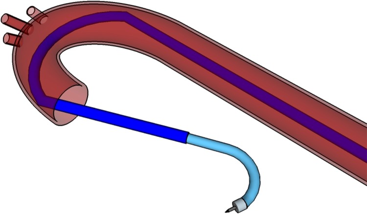
The catheter system is composed of 2 pieces: a 9-10.5 French catheter scale (Fr), outer catheter guide (OCG), and an 8 Fr inner operating catheter (IOC). The OCG provides access to the LV chamber and acts as a stabilizing mechanism for the IOC to pass through. It may be steerable, preshaped, or passed over a guide wire as a control mechanism. A preshaped OCG would use a SMA, such as nitinol, to curve the guide at 2 or more locations, providing stabilizing contact points around the descending and ascending aorta (see Fig. 1). The IOC contains the injection needle, a fiber optic contact force sensor, and a recording electrode to operate and receive feedback from within the LV. The robotic handle contains actuators controlling the IOC and its components, a microprocessor control unit, a demodulator for the fiber optic signal, and circuitry to filter and amplify the electrode signal.
Figure 1.
Model of the outer catheter guide (OCG) and inner operating catheter (IOC) with access to the left ventricle (LV) cavity. The OCG is preshaped to provide 2 stabilizing contact points in the aorta, and the IOC contains the necessary operating equipment to complete the procedure.
To begin the operation, the OCG is inserted through the femoral artery and passed through the descending and ascending aorta until it is situated 1 quarter of the way into the LV. Once the OCG reaches the desired destination point, it is locked into place at the proximal end. The IOC is passed through the OCG to access the LV chamber, and the catheter tip is manipulated to rest at the LV’s apex. This position is designated as the starting point of the procedure with the Cartesian origin of (0, 0, 0). Inside the distal end of the IOC is a needle that can protrude from the catheter tip and inject cell solution into the LV endocardium. The tip can also deflect in all directions using 4 orthogonal pull wires attached to the distal end. Pulling on 1 wire would deflect the catheter in 1 direction along a quadrant axis. When 2 adjacent pull wires are pulled simultaneously, the catheter deflects within the quadrant of the 2 pull wires. As there is a total combination of 4 adjacent pull wire pairs that may be actuated simultaneously (1 pull wire pair for each quadrant), the catheter may achieve omnidirectional deflection.
For complete robotic movement of the IOC, each maneuverable component is controlled from the proximal end by an actuator in the catheter handle. Each actuator can be controlled remotely or autonomously through a microprocessor. The robotic handle consists of an inner and outer components. The inner component is a linearly moving platform that slides on the top of the immobile outer component by means of an actuator. The IOC is connected to the inner component and moves synchronously with it. Four additional actuators are also attached to the inside of the inner platform, each individually controlling a pull wire.
A needle is situated inside the catheter tip and its tubing runs along the length of the catheter where it extends outwards into the inner component of the handle. The needle is preshaped to be curved upon protrusion in order to achieve a diagonal injection. Inside the catheter handle, 2 actuators control the insertion of the needle and the injection of the cells. The infarct boundary zones are determined by the electrode biopotential readings once the catheter makes sufficient contact with the endocardial surface. Accurate and precise movement or deflection of the catheter tip and needle is accomplished with both automated feedforward and feedback control, where the system is calibrated in the LV before the procedure begins.
Electromechanical Assembly of Prototype
The handle was formed by constructing 3-dimensional (3-D) printed structures made up of 70% polylactic acid (PLA) infill. The printed structures consisted of an outer handle, an inner handle, and various parts to hold or connect the actuators to the pull wire and needle (Fig. 2). The IOC tubing consisted of a modified Myostar® (Biosense Webster, a Johnson & Johnson company, Diamond Bar, CA, USA) with 1 pull wire and a 27-gauge needle. Whereas only a single direction of deflection was explored in this bench test, the prototype handle was built to be capable of actuating up to 4 pull wires. Industrial grade cyanoacrylate adhesive or nuts and bolts were used to fix appropriate components together, and ball bearings were used to slide the inner handle within the outer handle. The actuators used to manipulate each component of the catheter were bipolar 4 wire Nema 17 42 × 42 mm stepper motors (GEMS Motor, North St. Paul, MN, USA), with a step angle of 1.8° and a current of 1.2 A.
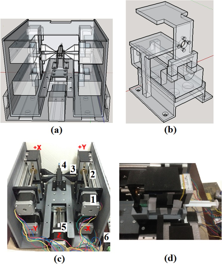
Figure 2.
(a) Rear view of the 3-dimensional model of catheter prototype handle. A mechanical slide actuates the inner handle, which is attached to the catheter body while up to 4 mechanical slides are attached to the walls of the inner handle, each capable of pulling 1 pull wire. (b) 3-dimensional (3-D) model of the holder and contraption for the syringe. (c) 3-D printed prototype of the catheter handle. (1) Nema 17 42 × 42 mm stepper motor. (2) 10 mm linear mechanical slide. (3) Stepper motor to pull wire connector. (4) Pull wire from catheter attached to connector. (5) Stepper motor slide is fixed onto the outer platform that slides the inner handle in a linear fashion. (6) Outer, nonmoving platform. (d) Arrangement of stepper motor and syringe fitted onto the 3-D printed components.
The stepper motors for the pull wire and inner handle were assembled onto a 10 cm linear mechanical slide. Both the pull wire and inner handle were attached to 3-D printed connectors, which in turn was fastened onto their respective mechanical slide. The actuator for the pull wire was attached to the inner wall of the inner handle, while the actuator for the inner handle was fixed onto the outer handle. The needle tubing extending from the proximal end of the catheter was connected to a syringe that was locked into a mobile contraption within the inner handle. The linear movement of this contraption, and thus the needle, was controlled by a stepper motor attached to the inner handle. In this manner, the actuation of the pull wire and needle within the catheter was independent of the actuation of the inner handle. If the inner handle, and thus the IOC, is actuated, the pull wire, needle, and their actuators and slides maintain their relative position within the catheter body as they are fixed onto the inner handle.
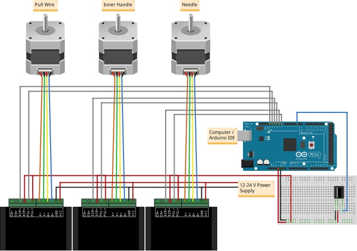
For linear actuation, the stepper motors were attached to stainless steel threaded rods with spring-loaded nuts to prevent the loss of precision while changing directions due to backlash. Each stepper motor was controlled by a TB6600 2 phase stepper motor driver (Haoyu Electronics, Shenzhen, China) where the microstep was set to 8 and output current set to 1.5 A. The drivers were powered by an S-100-24 power supply (Mean Well Enterprises Co., Ltd., New Taipei City, Taiwan) and connected to an Arduino Mega 2560 (Atmel Corporation, San Jose, CA, USA) containing an ATmega2560 microcontroller. Arduino is an open-source electronics platform suitable for rapid robotic prototyping. The Mega 2560 was chosen for its multiple serial ports and increased pins with 54 input/output pins and 16 analog inputs. The increased number of serial ports and pins was desirable for the future inclusion of equipment such as recording electrodes, optical fibers, and additional actuators. The Arduino was connected to a computer by means of a USB cable and programmed using Arduino’s integrated development environment (IDE) software. An optional infrared receiver was also added in order to control the catheter system remotely. Figure 3 shows an illustration of the electromechanical assembly.
Figure 3.
Illustration of an Arduino Mega 2560 setup with stepper motors, TB6600 drivers, and an infrared receiver. Each stepper motor is fixed onto a mechanical slide that actuates the catheter pull wire, inner handle, or needle.
Calibration of Stepper Motors
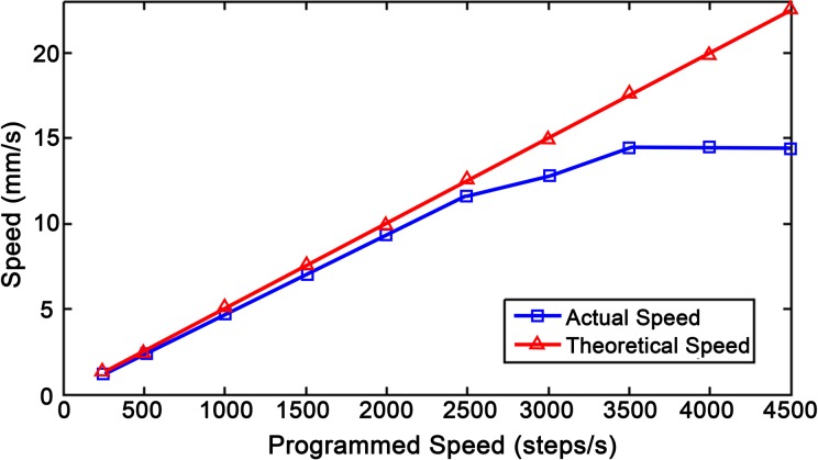
The mechanical slides theoretically moved at 8.0 mm per revolution or 0.040 mm per full step of the stepper motor. Using the open-source video analysis and modeling software Tracker (version 4.9.8) (http://physlets.org/tracker/), the actual distance traveled for a stepper motor with a load was measured and compared to a known distance entered into the Arduino IDE (version 1.8.3). The known distance was measured as the number of steps that the motor rotated, while the actual distance traveled was designated in millimeters. With a single revolution being 200 full steps and each step being divided into 8 micro-steps, it took 1,600 micro-steps to complete 1 revolution. Hereafter, the term “step” refers to 1/1,600 of a revolution. The forward and reverse distances for 1 revolution were measured over 10 different speeds starting from 250 to 4,500 steps/second (steps/s). The actual speed for each of the programmed speeds and the maximum achievable speed was also derived.
Bench Top Set-Up and Test Methods
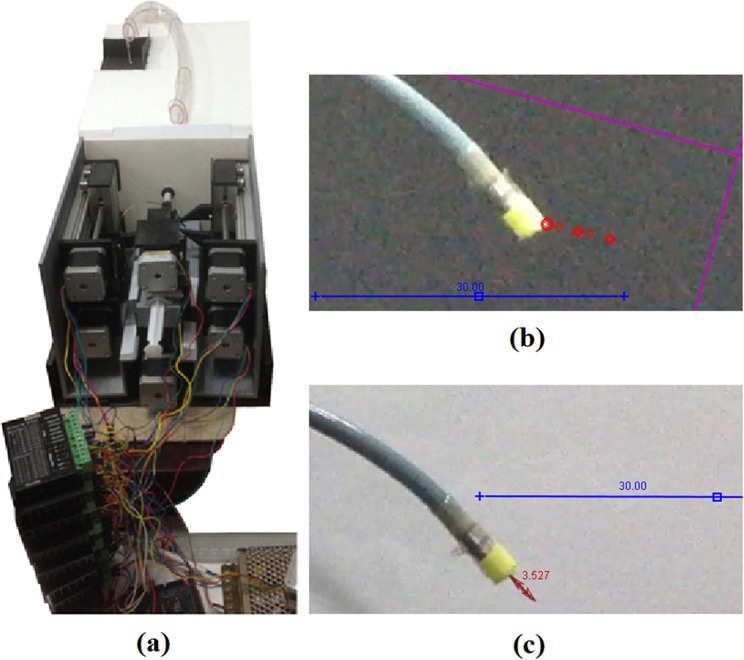
A bench top arrangement for an LV catheter procedure with femoral entry was assembled using polyvinyl chloride (PVC) tubing and a styrofoam platform as the operational environment (Fig. 4A). The PVC tubing represented the pathway to the LV starting from the femoral access point. A 10.5 Fr polytetrafluoroethylene (PFTE) tubing, acting as the OCG, was fixed onto the proximal end of the platform and passed through the PVC tubing. The 3-D printed handle was set onto the table where the attached IOC was streamed through the OCG, passed the aortic curvature, and into a region designated as the LV.
Figure 4.
(a) Bench setup of the robotic handle and catheter in an operational simulation. (b) Example of the catheter tip coordinates being tracked during linear movement and deflection. (c) Example of the needle protrusion length measured during tip deflection.
A video camera was set up to record the movement and behavior of catheter tip at the assumed LV region. A yellow tag was attached to the catheter tip, and the experiment was recorded against a black background to emphasize the color contrast for the video modeling tool. The actuators for the catheter body and pull wire were independently maneuvered, and the tip of the catheter’s movement and deflection was recorded on camera. The stepper motor manipulating the catheter body was programmed to move at multiple locations in iterative sequences with varying lengths and directions with a maximum range of 20 mm for a total of 158 movements. These sequences were repeated at 5 different speeds. The camera was also angled to be parallel to the catheter to capture its linear movement.
The stepper motor for the pull wire was actuated up to 9 mm, at increments of 1 mm, and the curvature of the pull wire was measured on a planar dimension for each increment. The needle length was also measured at various degrees of deflection as varying the curvature in the catheter may affect its extension length. The needle was also incrementally retracted at different degrees of deflection. Tracker was used to measure the needle lengths and distances traveled by the catheter tip, whereas Matlab 2011b (MathWorks Inc., Natick, MA, USA) was used to reorganize and model the data.
Calibration Method
Based on the compiled data, empirical models for the catheter movement, deflection, and needle movement were obtained. The models were integrated into the IDE program of the Arduino to compromise for discrepancies between the displacement of the actuators and the actual displacement of the catheter and needle. As linear catheter movement was 1-dimensional and the single degree of deflection is 2-dimensional, the 2 profiles were combined into a planar model where linear movement occurred on the z-axis and deflection occurred on both the y- and z-axes. The Arduino was then programmed to allow the user to input a planar coordinate within the appropriate range (0 mm ≤ y ≤ 15 mm, 0 mm ≤ z ≤ 20 mm), where the actuators moved in accordance with a calibrated value based on the empirical models. Using the same video analysis methods, the actual coordinates of the catheter were again tracked with a sample size of 26 different coordinates and compared to the input values after calibration.
Statistical Analysis
All movements of the catheter tip or needle were recorded in Tracker and plotted in Matlab, where a linear or polynomial regression was taken to represent the behavior of the system. These behaviors were incorporated into an algorithm written in Arduino to provide a feedforward control system. The F test and t test were then used to respectively compare the equality of variance and significance of difference between the coordinates of the calibrated or unmodified catheter tip control system versus the theoretical coordinates entered by the user. The RMS errors were also calculated for the calibrated and unmodified tip coordinates.
Stepper Motor Speed and Revolution Distance
The actual speed of the loaded stepper motors compared to the programmed steps (ST) per second was plotted in Matlab with standard deviations ranging from 0.018 to 0.076 mm (Fig. 5). The average distance traveled per revolution in either direction over multiple speeds was 7.7 ± 0.081 mm. Using the actuated distance of 7.7 mm per revolution, the number of steps required to travel a given distance, d (mm), was calculated given that 1 revolution is 1,600 steps.
Figure 5.
A comparison between the theoretical and actual speeds of a loaded stepper motor.
| 1 |
The stepper motors were thus assumed to be accurately controlled by using the modified step values.
Profile for Linear Tip Movement
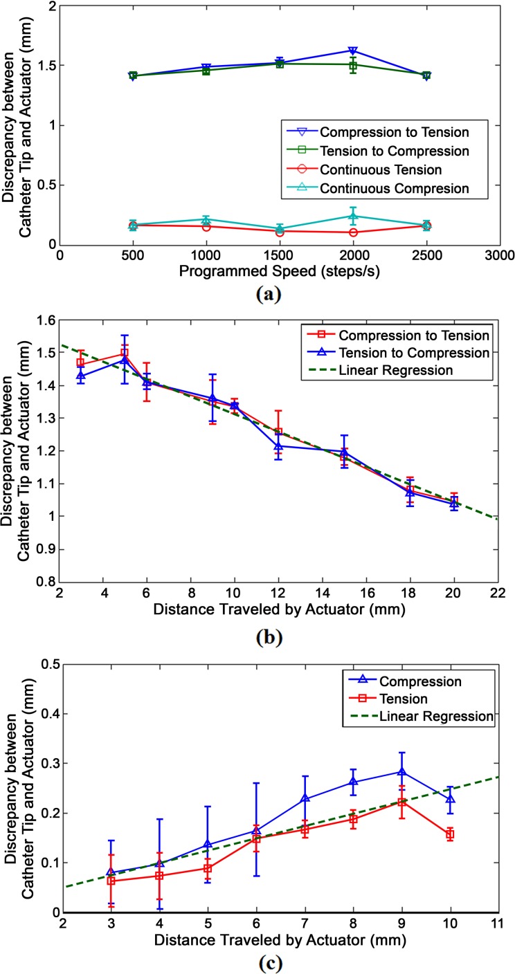
Figure 6 shows 3 graphs depicting the linear displacement of the catheter caused by the linear actuation of the inner handle. The y-axis of all 3 graphs represents the difference between the actual distance traveled by the catheter tip and the distance of actuation caused by the stepper motor at the proximal end. Figure 6a plots this discrepancy over various stepper motor speeds. Figure 6b and 6c plots this discrepancy over the distance traveled by the actuator. Figure 6b shows the graphical profile of the catheter when it continuously travels in 1 direction, whereas Figure 6c shows the profile of the catheter when it is changing in direction from tension to compression or vice versa. Note that the values in 6b and 6c are absolute values. In situations where the actuator changed directions, the catheter consistently undershot and moved at a lesser distance than the actuator. Conversely, the catheter slightly overshot compared to the actuator when it was being moved in the same direction.
Figure 6.
Behavioral profiles of the difference between the linear distance traveled by the catheter tip and the distance traveled by the actuator manipulating the catheter body. (a) Linear movement profile over different speeds. (b) Linear movement profile when changing directions at different lengths. (c) Linear movement profile when traveling in the same direction at different lengths.
The compression and tension profiles in each behavioral model were averaged to form a linear regression approximation. The original slope of graphs 6b and 6c were 0.02475 and −0.0267, respectively. Given the close proximity of the absolute values of the 2 slopes, an assumption was made where discrepancies caused by movement in a continuous direction had an inverse relationship between the discrepancies caused by movement in opposite directions. The displacement profile for a change in direction and displacement profile for continuous direction are represented by (2) and (3), respectively.
| 2 |
| 3 |
In the above equations, Δac represents the absolute value of the distance traveled by the actuator controlling the catheter’s linear movement, measured in mm. dc is the difference between the distance traveled by the catheter tip and the distance traveled by the actuator and also measured in millimeters.
Profile for Tip Deflection
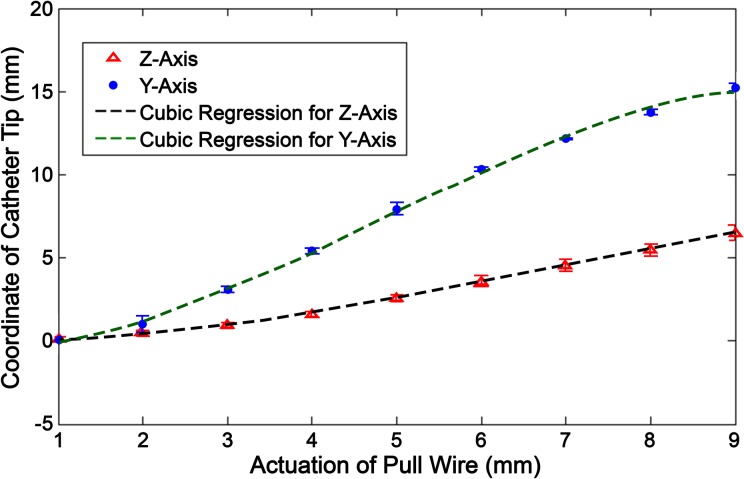
The deflection of the pull wire was measured on its y–z plane, and the coordinates of the catheter tip were measured for each incremental actuation of the stepper motor. The position of the tip was then plotted against the linear actuation of the pull wire (Fig. 7). Two graphical functions are derived in the y- and z-axis, respectively, as seen in equations (4) and (5). apw (mm) represents the distance that the pull wire is actuated, whereas ypw (mm) and zpw (mm) represent the absolute value of the tip’s y and z coordinates in relation to its original position (where apw = 0).
Figure 7.
Stationary deflection profile where the tip coordinate is measured based on incremental actuation (ie, tension) of the pull wire.
| 4 |
| 5 |
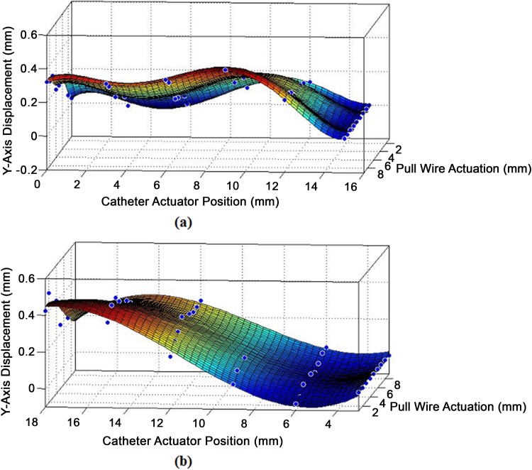
Theoretically, the y-axis coordinate should solely be determined by the actuation of the pull wire. However, the tip’s deflection causes a supposedly straight section of the catheter to slightly bend and stiffen, skewing the y-axis coordinate from its original value. In turn, this deformity affects the y-axis position, while the catheter is being linearly moved along the z-axis. Figure 8a and 8b shows 3-D surface graphs of the change in y-axis value from its original position at increasing degrees of deflection when faced with linear compression or tension.
Figure 8.
(a) Displacement in y-axis while the deflected catheter is being moved under compression. (b) Displacement in x-axis while the deflected catheter is being moved under tension.
The surface fit generated in Matlab for y-axis displacement during compression yielded a 5° polynomial regression with 2 indeterminate variables forming 20 features and 21 parameters. The surface fit for the deflected tip’s behavior under tension yielded a 3° polynomial regression with 2 indeterminate variables forming 9 features and 10 parameters. The 2 equations take on the form:
where yc represents the change of the catheter position along the y-axis caused by applying linear tension or compression to the catheter while it is deflecting. The parameters (θ0 to θn) of equation (6) and their matching features are listed in Table 1.
Table 1.
Parameters for Y-Axis Model Under Linear Movement and Deflection.
| Compressiona | Tensiona | ||
|---|---|---|---|
| Parameters | Features | Parameters | Features |
| 0.185 | 1 | 0.2959 | 1 |
| −0.3438 | a pw | 0.03744 | a pw |
| 0.1178 | zc | −0.1764 | zc |
| 0.2441 | a pw 2 | −0.01379 | a pw 2 |
| −0.02831 | a pw z c | 8.859E−3 | a pw 3 |
| −0.06484 | zc 2 | 0.0278 | a pw 2 ·z c |
| −0.06264 | a pw 3 | 9.538E−4 | a pw 3 |
| 0.003804 | a pw 2 · z c | −1.273E−4 | a pw 2 ·z c |
| 0.004771 | a pw · zc 2 | −4.86E−4 | a pw ·zc 2 |
| 0.01234 | zc 3 | −5.882E−4 | zc 3 |
| 6.973E−3 | a pw 4 | ||
| −2.169E−4 | a pw 3 · zc | ||
| −2.789E−4 | a pw 2 · zc 2 | ||
| −3.778E−4 | a pw · z c 3 | ||
| −9.163E−4 | zc 4 | ||
| −2.818E−4 | a pw 5 | ||
| 6.832E−6 | a pw 4 · z c | ||
| 3.021E−6 | a pw 3 · z c 2 | ||
| 8.916E−6 | a pw 2 · z c 3 | ||
| 9.773E−6 | a pw · z c 4 | ||
| 2.323E−5 | zc 5 | ||
aPolynomial regression for y-axis displacement where yc = f(apw, zc).
Profile for Needle Protrusion and Retraction
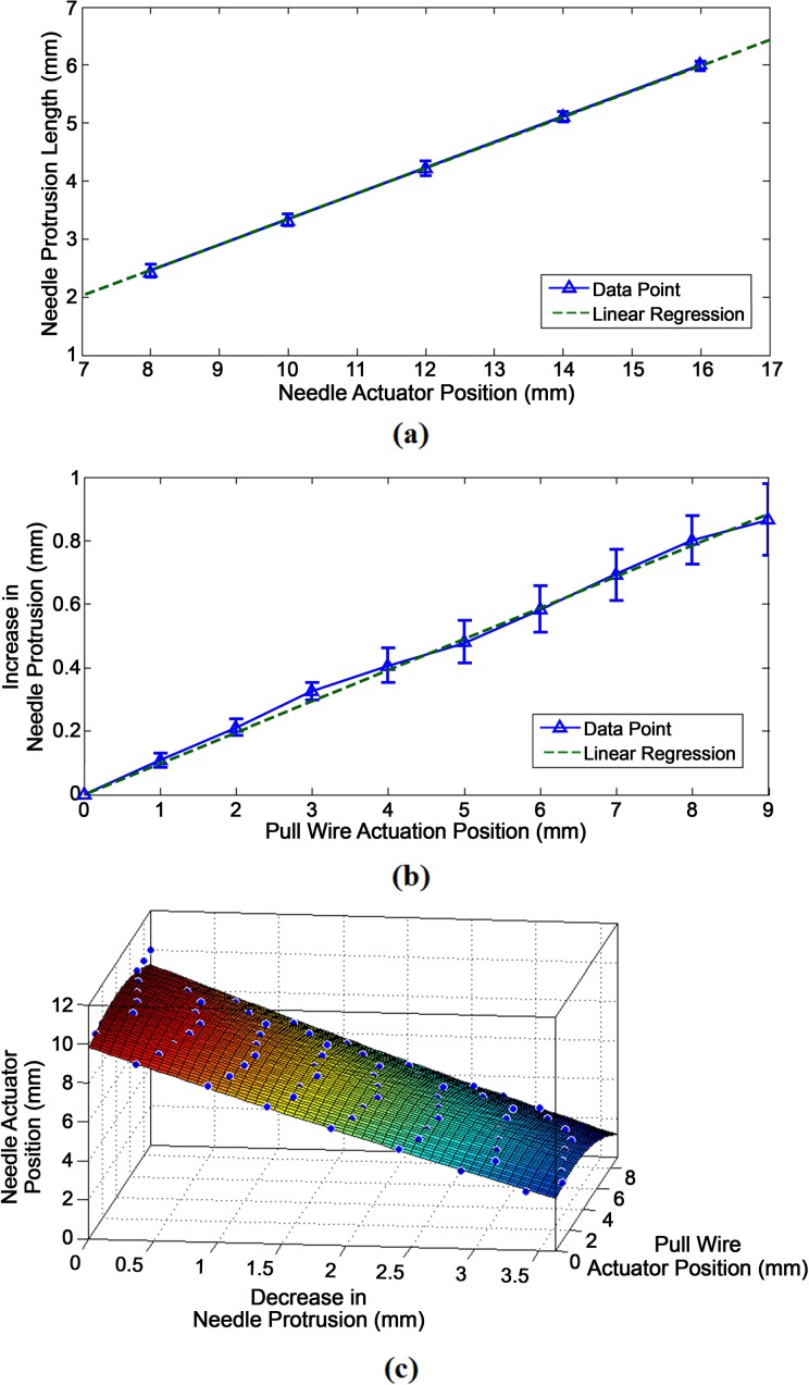
Figure 9 displays the different behavioral profiles for the protrusion and retraction of the needle at varying degrees of deflection. Figure 9a plots the needle protrusion length against the forward, compressive actuation of the needle. Based on its linear regression, it follows the linear profile of:
Figure 9.
(a) Graph of the needle protrusion length compared to the needle actuator position after compression or forward movement. (b) Graph of the increase in protrusion length while the catheter is deflecting. (c) 3-dimensional (3-D) surface fit of the decrease in protrusion length while the needle actuator is retracting.
| 7 |
where ln (mm) is the needle protrusion length and an (mm) is the needle actuation position. Figure 9b plots the increase in needle protrusion length, Δln (mm), against the actuator position of the pull wire, apw, yielding the linear profile:
| 8 |
Figure 9c shows a 3-D surface fit for the decrease in needle protrusion length based on the actuated retraction of the needle over varying degrees of deflection. As the absolute value of the change in needle length is given, the decrease in protrusion length is still represented by Δln. The needle actuator position is also plotted along the z-axis, so that it could be derived as a function of the desired decrease in needle length and the pull wire actuator position.
| 9 |
In this manner, the needle actuator may be calibrated to decrease based on equation (9) as catheter deflection causes the needle to extend further based on equation (8).
Results
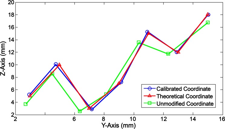
The attained behavior profiles of the catheter movement, deflection, and needle were compiled to create a feedforward algorithm, where accurate positioning was achieved in a planar field. The algorithm accepts 3 input values: the desired catheter tip coordinate (yi, zi) and the needle protrusion length (ln). The z-axis represents linear movement of the catheter, and the y-axis represents the planar deflection of the catheter. The algorithm yields an output value that equals the position that the pull wire, needle, and catheter actuators are required to move to in order for the catheter tip to reach the same location as the given initial input conditions. Testing for 26 planar coordinates, the calibrated catheter tip movement was compared to the theoretical input values using the same Matlab and Tracker methods of determining the coordinate location. Figure 10 shows a sample of these data comparing the calibrated values to the desired input values and unmodified values. The unmodified values only uses equations (4) and (5) to account for the deflection of the catheter and does not adjust for the catheter’s linear movement or deviation caused by deflection.
Figure 10.
Data sample of the calibrated catheter tip coordinates compared to theoretical and unmodified coordinate values.
The F test was used to determine the equality of variance between the calibrated and theoretical coordinates as well as between the unmodified and theoretical coordinates. In both scenarios, there was no significant difference in variance with a P value of 0.999 and 0.979 for the calibrated y- and z-coordinates, and 0.976 and 0.979 for the unmodified y- and z-coordinates. A 2-tailed Student’s t test was used to determine the significance of the discrepancy between calibrated and theoretical coordinate. The null hypothesis consisted of a mean of µ = 0, and alternative hypothesis was depicted by µ ≠ 0. The calculated P value was 0.4523 for the discrepancies in the y-axis and 0.3409 for the discrepancies in the z-axis. With P > 0.05 in both axes, the null hypothesis can be accepted, indicating that there was no significant difference between the calibrated and theoretical values. Similarly, a t test was performed for the discrepancy between the unmodified and theoretical values. The P value for the unmodified y-coordinates was 3.89E−4 and 9.22E−4 for the z-coordinates, yielding strong evidence against the null hypothesis as P < 0.01. Therefore, the unmodified movement of the catheter was significantly different from the theoretical values. Alternatively, the root mean square (RMS) errors for the unmodified coordinates were calculated to be 1.22 mm in the z-axis and 0.58 mm in the y-axis. The RMS errors for the calibrated coordinates were 0.14 mm in the z-axis and 0.18 mm in the y-axis, showing an 88% and 31% improvement, respectively.
The calibrated needle was protruded to a theoretical length of 3, 4, and 5 mm, while the pull wire stepper motor was actuated to 8 mm at increments of 2 mm. The actual needle protrusion lengths were measured (Table 2) and compared to the theoretical value. The standard deviation for the discrepancy between the calibrated needle lengths and the theoretical length was ±0.042 mm.
Table 2.
Needle Calibration.
| Pull Wire Actuator Position (mm) | Difference Between Programmed and Actual Needle Protrusion Length Starting From | ||
|---|---|---|---|
| 3 mm | 4 mm | 5 mm | |
| 0 | .07 | .111 | .093 |
| 2 | .07 | .111 | .093 |
| 4 | .003 | .069 | .093 |
| 6 | .046 | .138 | .121 |
| 8 | .092 | .129 | .183 |
Discussion
Accurate planar movement was achieved where there was no significant difference in the discrepancy of the calibrated coordinates compared to the hypothetical mean, zero. Conversely, a significant difference was found when the t test was applied to the discrepancy of the unmodified manipulation, indicating that there was a significant difference in the unmodified coordinates compared to the theoretical coordinates. The RMS errors of the calibrated coordinates also showed 88% and 31% improvements in the z- and y-axes, respectively, compared to the unmodified coordinates.
The discrepancies in linear movement may be attributed to the compression and tension caused by the pushing and pulling of the IOC. The shifting of the 8 Fr IOC within the 10.5 Fr OCG would cause slight variations where the IOC moves freely inside the gap of the OCG lumen. More noticeably, as a regular PTFE tube was used for the OCG, the compression and tension forces caused the elastic tubing to bend while being pushed and straighten while being pulled, leading to a larger discrepancy when the catheter actuator changed the directions. For future considerations, an OCG with variable stiffness and with a pre-shaped section for stability at the ascending and descending aorta may enhance the controllability of the IOC.
Actuating the needle also showed discrepancies during catheter deflection as well as when the needle was being retracted versus extended. This behavior was largely due to the needle lumen being much smaller than the inner diameter of the catheter lumen. The needle lumen was not fixed in a radial position within the catheter and was susceptible to moving from side to side as well as bending or straightening during compression and tension. Though we were able to achieve ±0.042 mm precision after calibrating the needle, the needle lumen should have less freedom of movement in future designs to minimize variability. As the needle cannot be calibrated inside the LV, the physician should be able to choose from a selection of catheter sizes and calibration models matching the body size of the patient prior to the operation.
The Arduino system, 3-D printed components, and electromechanical tools used were cost-effective prototyping methods meant for a proof of concept experiment. Continuity with this design concept for in vivo trials requires a faster software environment and microprocessor, higher quality structural components, and a specially manufactured OCG and IOC.
This bench test is performed on a nonmoving platform, which differs from an in vivo procedure where a beating heart and slight movements of the patient may alter the parameters of the empirical models. To resolve this problem, the feedforward model should account for the catheter position during both systole and diastole. Furthermore, self-calibration algorithms based on feedback from soft tissue imaging analysis, using navigational systems such as ultrasound, should be implemented in the background where the software can check and occasionally update the model parameter values if necessary. Aside from ultrasound, an electromagnetic position sensor or fluoroscopy can be used to track the location of the catheter tip. The catheter tip position is then compared to prerecorded static images where its coordinates relative to the intracardiac structures can be determined. Using these methods, positional feedback can be combined with the feedforward model to allow automated control.
Future work includes the development of an omnidirectional catheter with force sensing capabilities. A feedforward model for the positioning of the omnidirectional catheter should be derived using kinematic or empirical models. Following bench experiments, porcine trials should be used to determine the accuracy and precision of the robotic system in a variable and moving environment. Once feedforward control is established in vivo, feedback control should also be implemented to optimize the system. Outside of automated positional control, other future experiments include the development of automated control for the needle and injection process, the determination of infarct boundary zones via recording electrodes, and determining contact force thresholds whenever the catheter tip encounters an intracardiac structure. Combining these functions into a step-by-step sequence, a complete or partially autonomous catheter injection procedure can be developed where minimal intervention from the physician is required.
An unexplored method in deriving complex models and algorithms for catheter systems is through machine learning where predictive models are generated using a given learning data set. In this scenario, dynamic simulations of an intracardiac environment and robotic catheter can be created with feedback signals available to the learning system, such as the catheter’s position, contact force at the tip, or ECG readings. These simulations are set up so that the end objective of the algorithm or model is to optimize the performance of specific tasks in a catheter procedure. For instance, in order to accurately maneuver the catheter, the algorithm would have the objective of recognizing the dynamical pattern of the catheter tip movement within a simulated LV. In order to pinpoint target injection sites, the algorithm’s objective would be to recognize the in situ biopotential signature of the infarct boundary zones. In this manner, automation or autonomy can be achieved in algorithms or models otherwise too complex to be explicitly programmed.
A feedforward empirical model for the planar positioning of a robotically controlled cell injection catheter has been established. The calibrated coordinate control was not significantly different from the theoretical coordinates, while the unmodified values show strong significant difference. The RMS error in the calibrated movements showed an 88% improvement in the z-axis and 31% improvement in the y-axis compared to the unmodified test run. Calibrated needle control also yielded a standard deviation of ±0.042 mm in its discrepancy from the theoretical value. Empirical models may offer more clues in determining the forces that influence the control of the catheter, such as the slight changes in projection when the catheter was under different modes of deflection. Having such models available also gives rise to the possibility of autonomous systems or functions that perform parts of a complex procedure, minimizing the required learning curve of the operator as well as the operation time.
Acknowledgments
The authors would like to acknowledge Biosense Webster for the use of their Myostar® intramyocardial injection catheter.
Authors’ Note: This myogenic cell injection catheter and method was originally patented in 2005 by Law PK.
Statement of Human and Animal Rights: This article does not contain any studies with human or animal subjects.
Statement of Informed Consent: There are no human subjects in this article and informed consent is not applicable.
Declaration of Conflicting Interests: The author(s) declared no potential conflicts of interest with respect to the research, authorship, and/or publication of this article.
Funding: The author(s) received no financial support for the research, authorship, and/or publication of this article.
References
- 1. Mozaffarian D, Benjamin EJ, Go AS, Arnett DK, Blaha MJ, Cushman M, Das SR, de Ferranti S, Després JP, Fullerton HJ, et al. Heart disease and stroke statistics—2016 update: a report from the American Heart Association. Circulation. 2016;133(4): e38–360. [DOI] [PubMed] [Google Scholar]
- 2. Issa Z, Miller JM, Zipes DP. Advanced mapping and navigation modalities In: Issa Z, Miller JM, Zipes DP, editors. Clinical arrhythmology and electrophysiology: a companion to Braunwald’s heart disease. 2nd ed. Philadelphia (PA): Elsevier; 2012. p. 111–143. [Google Scholar]
- 3. Pappone C, Vicedomini G, Manguso F, Gugliotta F, Mazzone P, Gulletta S, Sora N, Sala S, Marzi A, Augello G, et al. Robotic magnetic navigation for atrial fibrillation ablation. J Am Coll Cardiol. 2006;47(7):1390–1400. [DOI] [PubMed] [Google Scholar]
- 4. Datino T, Arenal A, Pelliza M, Hernández-Hernández J, Atienza F, González-Torrecilla E, Avila P, Bravo L, Fernández-Avilés F. Comparison of the safety and feasibility of arrhythmia ablation using the Amigo robotic remote catheter system versus manual ablation. Am J Cardiol. 2014;113(5):827–831. [DOI] [PubMed] [Google Scholar]
- 5. Horton RP. Remote catheter navigation systems In: Huang SKS, Miller JM, editors. Catheter ablation of cardiac arrhythmias. 3rd ed. Philadelphia (PA): Elsevier Saunders; 2014. p. 153–161. [Google Scholar]
- 6. Fu Y, Liu H, Huang W, Wang S, Liang Z. Steerable catheters in minimally invasive vascular surgery. Int J Med Robot. 2009;5(4):381–391. [DOI] [PubMed] [Google Scholar]
- 7. Petru J, Skoda J. Robot-assisted navigation in atrial fibrillation ablation – of any benefits? Cor Vasa. 2012;54(6):408–413. [Google Scholar]
- 8. Muller L, Saeed M, Wilson MW, Hetts SW. Remote control catheter navigation: options for guidance under MRI. J Cardiovasc Magn Reson. 2012;14(1):33. [DOI] [PMC free article] [PubMed] [Google Scholar]
- 9. Szili-Torok T, Dabiri L, de Groot N, Jordaens L. Toward a fully remote solution for atrial fibrillation: first Worldwide use of integrated robotic and magnetic catheter navigation systems. EP Lab Digest. 2011;11(6). [Google Scholar]
- 10. Miller JM, Dixon MA, Bhakta D, Rahul J, Das MK. Magnetic and robotic catheter navigation In: Steinberg JS, Jais P, Calkins H, editors. Practical guide to catheter ablation of atrial fibrillation. Chichester (UK): Wiley Blackwell; 2015. p. 75–83. [Google Scholar]
- 11. Carrell T, Dastur N, Salter R, Taylor P. Use of a remotely steerable “robotic” catheter in a branched endovascular aortic graft. J Vasc Surg. 2012;55(1):223–225. [DOI] [PubMed] [Google Scholar]
- 12. Kanagaratnam P, Koa-Wing M, Wallace DT, Goldenberg AS, Peters NS, Davies DW. Experience of robotic catheter ablation in humans using a novel remotely steerable catheter sheath. J Interv Card Electrophysiol. 2008;21(1):19–26. [DOI] [PMC free article] [PubMed] [Google Scholar]
- 13. Santangeli P, Biase LD, Burkhardt JD, Horton RP, Sanchez J, Al-Ahmad A, Hranitzky P, Natale A. Pulmonary vein isolation for atrial fibrillation In: Huang SKS, Miller JM, editors. Catheter ablation of cardiac arrhythmias. 3rd ed. Philadelphia (PA): Elsevier Saunders; 2015. p. 275–287. [Google Scholar]
- 14. Weisz G, Metzger C, Caputo RP, Delgado JA, Marshall JJ, Vetrovec GW, Reisman M, Waksman R, Granada JF, Novack V, et al. Safety and feasibility of robotic percutaneous coronary intervention. J Am Coll Cardiol. 2013;61(15):1596–1600. [DOI] [PubMed] [Google Scholar]
- 15. Granada JF, Delgado JA, Uribe MP, Fernandez A, Blanco G, Leon MB, Weisz G. First-in-human evaluation of a novel robotic-assisted coronary angioplasty system. JACC Cardiovasc Interv. 2011;4(4):460–465. [DOI] [PubMed] [Google Scholar]
- 16. Magallon JC, Weisz G. Robot-assisted coronary intervention In: Thompson CA, editor. Textbook of cardiovascular intervention. London (UK): Springer Verlag; 2014. p. 157–166. [Google Scholar]
- 17. Ma Y, Gogin N, Cathier P, Housden RJ, Gijsbers G, Cooklin M, O’Neill M, Gill J, Rinaldi CA, Razavi R, et al. Real-time X-ray fluoroscopy-based catheter detection and tracking for cardiac electrophysiology interventions. Med Phys. 2013;40(7):071902. [DOI] [PubMed] [Google Scholar]
- 18. Shah AJ, Lim HS, Yamashita S, Zellerhoff S, Berte B, Mahida S, Hooks D, Aljefairi N, Derval N, Denis A, et al. Non-invasive ECG mapping to guide catheter ablation. J Atr Fibrillation. 2014;7(3):31–38. [DOI] [PMC free article] [PubMed] [Google Scholar]
- 19. Calabria M, Zamboli P, D’Amelio A, Granata A, Di Lullo L, Floccari F, Logias F, Fiorini F. Use of ECG-EC in the positioning of central venous catheters. G Ital Nefrol. 2012;29(1):49–57. [PubMed] [Google Scholar]
- 20. Friedman PA. Novel mapping techniques for cardiac electrophysiology. Heart. 2002;87(6):575–582. [DOI] [PMC free article] [PubMed] [Google Scholar]
- 21. Gerstenfeld EP. Contact force-sensing catheters. Circ Arrhythm Electrophysiol. 2014;7(1):5–6. [DOI] [PubMed] [Google Scholar]
- 22. Chu E, Kalman JM, Kwasman MA, Jue JC, Fitzgerald PJ, Epstein LM, Schiller NB, Yock PG, Lesh MD. Intracardiac echocardiography during radiofrequency catheter ablation of cardiac arrhythmias in humans. J Am Coll Cardiol. 1994;24(5):1351–1357. [DOI] [PubMed] [Google Scholar]
- 23. Biermann J, Bode C, Asbach S. Intracardiac echocardiography during catheter-based ablation of atrial fibrillation. Cardiology Research and Practice, 2012;2012:8, doi:10.1155/2012/921746. [DOI] [PMC free article] [PubMed] [Google Scholar]
- 24. Ma X, Guo S, Xiao N, Yoshida S, Tamiya T. Evaluating performance of a novel developed robotic catheter manipulating system. J Micro-Bio Robot. 2013;8(3-4):133–143. [Google Scholar]
- 25. Kesner SB, Howe RD. Position control of motion compensation cardiac catheters. IEEE T Robot. 2011;PP(99):1–11. [DOI] [PMC free article] [PubMed] [Google Scholar]
- 26. Law PK. Myogenic cell transfer catheter and method. WO Patent 0228470. 2011 Apr. 4; SI Patent 95355. 2005 May 31; EP Patent 1324802. 2015 Nov. 15; AU Patent 2002211230. 2007 Jun. 07; AU Patent 2007202290. 2012 Feb. 16; AU Patent 2012200651. 2015 May 14; US Patent 60 231 880 (pending).
- 27. Cheng W, Law PK. Conceptual design and procedure for an autonomous intramyocardial injection catheter. Cell Transplant. 2017;26(5):735–751. [DOI] [PMC free article] [PubMed] [Google Scholar]
- 28. Law PK, Goodwin TG, Fang Q, Vastagh G, Jordan T, Jackson T, Susan K, Duggirala V, Larkin C, Chase N, et al. Myoblast transfer as a platform technology of gene therapy. Gene Ther Mol Biol. 1998;1:345–363. [Google Scholar]
- 29. Law PK, Sim EKW, Haider KhH, Fang G, Chua F, Kakuchaya T, Repin VS, Bockeria LA. Myoblast genome therapy and the regenerative heart In: Kipshidze NN, Serruys PW, editors. Handbook of cardiovascular cell transplantation. London (UK): Martin Dunitz; 2004. p. 241–258. [Google Scholar]
- 30. Law PK, Chin SP, Hung HD, Nguyen TN, Feng QZ. Delivery of biologics for angiogenesis and myogenesis In: Nguyen TN, Colombo A, Hu D, Grines CL, Saito S, editors. Practical handbook of advanced interventional cardiology: tips and tricks, 3rd ed. Malden (MA): Blackwell; c2008. p. 584–596. [Google Scholar]


