

Abstract
Micro-Electrocorticography (μECoG) offers a minimally invasive, high resolution interface with large areas of cortex. However, large arrays of electrodes with many contacts that are individually wired to external recording systems are cumbersome and make chronic recording in freely behaving small animals challenging. Multiplexed headstages overcome this limitation by combining the signals from many electrodes to a smaller number of connections directly on the animal’s head. Commercially available multiplexed headstages provide high performance integrated amplification, multiplexing and analog to digital conversion[1], [2]. However, the cost of these systems can be prohibitive for small labs or for experiments that require a large number of animals to be continuously recorded at the same time. Here we have developed a multiplexed 60-channel headstage amplifier optimized to chronically record electrophysiological signals from high-density μECoG electrode arrays. A single, ultraflexible (2mm thickness) microHDMI cable provided the data interface. Using low cost components, we have reduced the cost of the multiplexed headstage to ~$125. Paired with a custom interface printed circuit board (PCB) and a general purpose data acquisition system (M-series DAQ, National Instruments), an inexpensive and customizable electrophysiology system is assembled. Open source LabVIEW software that we have previously released [3] controlled the system. It can also be used with other open source neural data acquisition packages [4][5]. Combined, we have presented a scalable, low-cost platform for high-channel count electrophysiology.
I. Introduction
Microelectrode arrays are a common tool in the study of cortical function. The use of μECoG as a recording array device has the advantages of design customization, material flexibility, minimal invasiveness, and low cost. Compact arrays utilizing microfabrication techniques are well suited to the challenge of recording at the scale of rodent cortical systems, while the material flexibility and scalability of fabrication allow for customized coverage of several adjacent systems. High channel density (sub-millimeter spacing) is also desirable in order to adequately sample cortical spatial dynamics, be it the topological representation of sensory features or a fine-pitch control signal for a brain machine interface [6]. As a non-penetrating recording modality, μECoG also causes little or no damage to the subdural meninges and cortical tissue during and after implantation.
However, μECoG arrays that interface with large areas of the cortical surface in rodents at high spatial resolution requires dozens to hundreds of electrodes. Obtaining chronic recordings from freely behaving animals with a large number of electrode contacts is challenging and expensive, which limits the number of animals that can be simultaneously recorded. To overcome this limitation, we have developed a low-cost, multiplexed headstage (Fig. 1) and interface system (Fig. 2) that directly interfaces with μECoG arrays.
Figure 1.
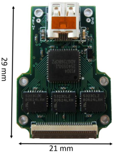
Low cost, 60 channel analog multiplexed headstage. The design included unity gain buffering, multiplexing, amplification and filtering in a small form factor. Three, 10-channel unity gain buffers (EL5323CLZ, Intersil Corporation), a dual 16:1 multiplexer (ADG726, Analog Devices, Inc) and a dual op-amp (gain of 10, OPA2376, Texas Instruments) were located on the front of the PCB. A duplicate set of these integrated circuits were located on the back side of the PCB (not shown). A high-density (0.4 mm pitch), 61-channel zero-insertion force (ZIF) connector (Fh43b, Hirose Electric Group) mates to the flexible μECoG array. A μHDMI connector was used to tether the headstage to our Interface Board (Fig. 2). Not shown: a 3-axis accelerometer is located on the back of the PCB.
Figure 2.
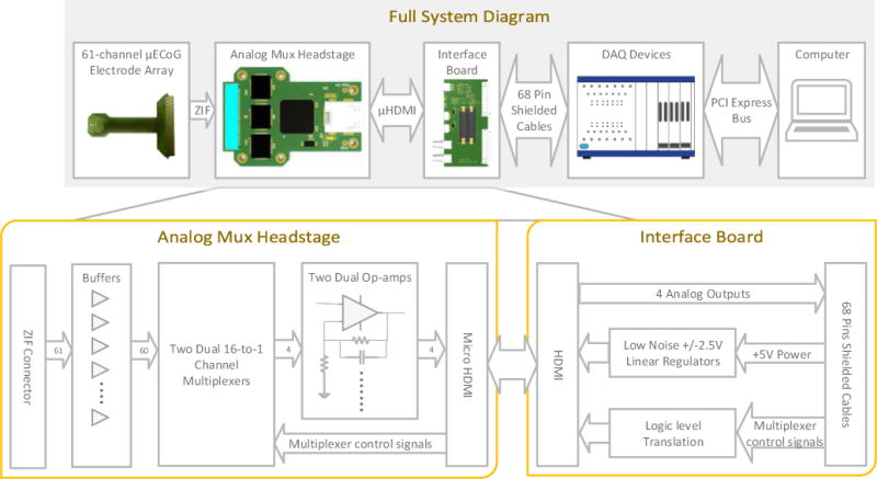
The electrophysiology system block diagram. (top) A custom μECoG array was connected to the multiplexed headstage through a high-density (0.4mm pitch) ZIF connector. The multiplexed headstage was connected to a custom interface board through a flexible (2 mm thickness), shielded microHDMI tether cable. An optional HDMI commutator can be added to prevent the microHDMI tether from becoming twisted during awake behaving recordings. The custom interface board connected to standard National Instruments M-series or X-Series data acquisition cards using shielded cables. Open source LabVIEW software running on a laptop or desktop computer controlled the data acquisition. (bottom) The multiplexed headstage included 60 op-amps connected to two dual 16:1 multiplexers. The four output signals were amplified by a factor of 10 and filtered by additional op-amps. The resulting signals were connected over separate shielded, twisted pairs to the interface board and on to the National Instruments data acquisition, also via shielded, twisted pairs to prevent additional noise coupling. The interface board provided regulated and filtered +/− 2.5V power for the multiplexed headstage and digital logic level translation. It did not include any additional analog signal processing.
II. Methods
A. Electrode array
The multiplexed analog headstage was specifically designed to record signals from a high-resolution μECoG array (Fig 2. Briefly, the μECoG array included 61 gold surface electrodes, each 203 μm in diameter and located on 406 μm centers. The average electrode impedance was 32 kΩ at 1 kHz. The electrodes were arranged in an 8 × 8 grid, covering 10.6 mm2. Three corner electrodes were omitted. The fourth corner electrode was intentionally not exposed to serve as a test for the resistance of the encapsulation in chronic implant experiments. Correspondingly, this electrode was omitted from the design of this headstage, reducing the number of active recorded sites to 60.
B. Analog multiplexed headstage
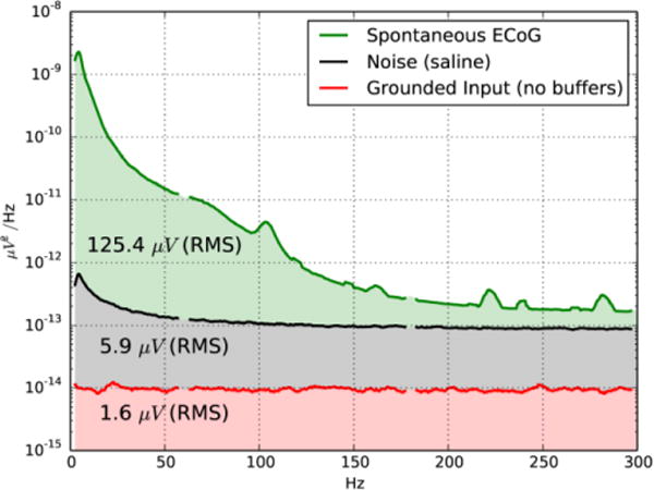
We designed the analog multiplexed headstage to be as physically small as possible. 10-channel unity gain buffers (EL5323CLZ, Intersil Corporation) provided initial buffering of the high impedance electrode signals. While the low-frequency (1/f) noise of these buffer amplifiers was higher than is desirable, their high level of integration (10 amplifiers per package) enabled the small form factor of the headstage to be maintained. The buffer amplifiers contributed the majority of the noise of the recording system. Unused inputs on each multiplexer were grounded, and as such the noise level of the multiplexers plus the gain stage op-amp could be measured (Fig. 4). The noise of the multiplexer grounded input channels was 1.6 μV RMS, while the noise of the headstage including the EL5323 buffer op-amps was 5.9 μV RMS.
Figure 4.
Comparison of μECoG signals in vivo, demonstrating the high signal to noise ratio (>26.5 dB) of the system.
The outputs of the buffer op-amps were directly connected to two, dual 16:1 multiplexers (ADG726, Analog Devices, Inc), reducing the 60 electrode inputs to four outputs. The extreme space constraints of the design did not allow for the addition of anti-aliasing filters at each channel prior to the multiplexer input. Ideally, low-pass filters should be added to the output of each buffer to remove high-frequency noise before converting to discrete time in the multiplexer. However, this omission did not have a large impact on the noise of our system, likely because there is little power present in the recorded μECoG above the nyquist frequency due to the 1/f characteristic of biological signals.
Following the multiplexers, each of the four signals were amplified by a factor of 10 using low-noise op-amps (OPA2376) in an ultra-small, die size ball grid array package. The gain was limited to prevent saturating the output of the op-amps. Since the electrodes are DC coupled, potential differences exist between each electrode channel, limiting the total gain that can be used in the system. We selected a gain of 10 to provide a wide input range (+/− 0.25V), while providing enough gain to reduce the impact of noise introduced in analog signal transmission to the remote analog to digital converter. An active low-pass filter (−3 dB, 240 kHz), provided some noise reduction before analog to digital conversion, while still settling to an 18-bit accurate output in less than 33 μs.
The outputs of the four op-amps were connected to a microHDMI connector. Four individually shielded, twisted pairs were used for analog signal transmission to the interface board and subsequently to the differential analog to digital converter (PXI-6289, National Instruments). Individual shielding, differential amplification and analog to digital conversion limited the noise introduced by the cables between the headstage and analog to digital converter.
C. Custom Interface PCB
Synchronized with analog to digital conversion, the data acquisition system (DAQ) generated a 4-bit select signal to cycle through the multiplexer channels. The four digital lines were converted from 5V logic to 2.5V logic on the interface PCB and sent to the analog multiplexed headstage. The four non-differential wires in the microHDMI cable were used as these signals were not susceptible to noise. The overall shielding of the microHDMI cable reduced radiated EMI at the multiplexer frequency.
The data acquisition system also provided 5V, 1A power to operate the acquisition system. On the interface PCB, the 5V power was inverted to produce a −5V supply. To reduce power supply noise, low noise positive and negative linear regulators were used to generate a filtered +/− 2.5V supply for the multiplexed analog headstage.
D. Data acquisition devices
The interface PCB was connected to multicard PXI system (PXI-6289) with 18-bit analog to digital converters. However, a USB-6289 or any M-series or X-series DAQ system would be compatible.
E. Software
Custom LabVIEW data acquisition software was used to control the acquisition and perform real-time demultiplexing, display and logging. We have previously published this software with an open source license[3].
III. Results
A. Bench top characterization
We characterized the performance of the system. The gain, input range and noise were measured (Table 1, Figure 4).
Table 1.
Low-Cost, Multiplexed Electrophysiology System specifications compared to commercially available headstages. Our headstage had comparable physical and electrical characteristics to systems costing 15–40 times more. Our system sampling rate was only tested up to 2 kS/s per channel because higher sampling rates are not required for μECoG signals. However, higher sampling rates should be feasible. Our system noise level was approximately two times higher than other systems due to the EL5323 amplifiers.
| Specifications | ||||
|---|---|---|---|---|
| This Work | Blackrock Microsystems | Intan Technologies RHD2164 | Neuralynx HS-36 | |
| Channel count | 60 | 64 | 64 | 36 |
| Dimensions | 29 × 21 × 6mm | 28 × 24 × 7mm | 22 × 14 × 5 mm | 27.9 × 21.1 × 4.1mm |
| Weight | <2.95 grams | <3.8 grams | 1.3 grams | 2.6 grams |
| Noise (input grounded) | 5.9μV RMS | 3μV RMS | 2.4μV RMS | 1.3μV RMS |
| Input impedance | 1 GΩ ‖ 1.35 pF | >10 GΩ ‖ 3 pF | 1.3 GΩ | 1TΩ |
| Sampling | >2 kS/s | 30 kS/s | 30 kS/s | |
| output cable/connector | μHDMI | 7 wires(36 AWG),Kevlar wrap (biting protection) | 12 wire custom interface | Dual-row, 44-pin, male, Omnetics nano |
| Input connector | 61-pin ZIF Connector | Dual-row, 36-pin, female, 0.025″ pitch Omnetics | Dual-row, 36-pin, female, 0.025″ pitch Omnetics | Dual-row, 44-pin, female, Omnetics nano |
| Power supply | +/− 2.5 V DC | +/−2.5 V to +/−5 V DC | 3.3V DC | +/−5 V DC |
| Resolution | 0.19 μV w/8x OSR | 0.225 μV | 0.195 μV | |
| Cost | ~$125 USD | ~ $5000 USD | $1,785 USD | |
B. In vivo measurements
We demonstrated the recording system in vivo. The μECoG array was placed directly on the subdural surface of auditory cortex in a rat. A 50ms pure-tone stimulus was presented and evoked responses were recorded. Single trial evoked responses could be recorded with high fidelity (Fig. 3).
Figure 3.
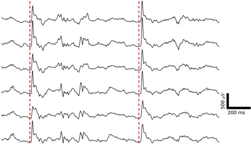
In vivo μECoG recording of single trial auditory evoked activity demonstrated high quality electrophysiology from the recording system. Six selected channels from the 60 channel μECoG array are shown. An auditory stimulus was presented at the times indicated by the dashed red lines. A clear, single trial auditory evoked response is visible approximately 15 ms after the stimulus. Ongoing background activity can also be observed.
We also compared the power spectral density of spontaneous μECoG (125.4 μV RMS, Fig. 4, green) to the noise level of the recording system including the op-amp buffers (5.9 μV RMS, Fig. 4, black) and the grounded inputs of the multiplexers, excluding the buffers (1.6 μV Fig. 4, red). We repeated similar noise measurements with grounded inputs to the buffer amplifiers and confirmed identical noise levels, confirming that the majority of the noise was due to the Intersil op-amps, not the electrodes.
IV. Discussion
While our multiplexed headstage had approximately two times higher noise than other commercially available multiplexed headstages, it still provided a high signal to noise ratio for μECoG recording (Fig. 3). The majority of the noise was contributed by the EL5323CLZ buffer amplifiers and could be improved in a future design by switching to a low noise amplifier.
Our system had the additional benefit of reduced implant size. While the multiplexing headstage is not significantly smaller than other multiplexed headstages, the low cost design enables it to be directly implanted chronically on the animal, eliminating an additional electrode adapter PCB to convert from the electrode to an omnetics connector. Besides reducing the height of the recording system by another ~15, it further reduces the cost of the implantation.
V. Conclusion
A low cost, multiplexed headstage enables high volume electrophysiology.
Acknowledgments
This work was supported by a Taking Flight Award from Citizens United for Research in Epilepsy.
Contributor Information
JuiChih Wang, Department of Electrical and Computer Engineering at New York University, Brooklyn, NY 11201 USA and NYU WIRELESS.
Michael Trumpis, Department of Electrical and Computer Engineering at New York University, Brooklyn, NY 11201 USA and NYU WIRELESS.
Michele Insanally, New York University School of Medicine, Skirball Institute of Biomolecular Medicine, 5th Floor, Lab 9, 540 First Avenue, New York, NY 10016.
Robert Froemke, New York University School of Medicine, Skirball Institute of Biomolecular Medicine, 5th Floor, Lab 9, 540 First Avenue, New York, NY 10016.
Jonathan Viventi, Department of Electrical and Computer Engineering at New York University, Brooklyn, NY 11201 USA, the Center for Neural Science at New York University, New York, NY 10003 USA and NYU WIRELESS.
References
- 1.Harrison R. RHD2000 Series Digital Electrophysiology Interface Chips. 2013 [Online]. Available: http://www.intantech.com/products_RHD2000.html.
- 2.Blackrock Microsystems. CerePlex M™. [Online] Available: http://www.blackrockmicro.com/content.aspx?id=38.
- 3.Bink H, Wagenaar JB, Viventi J. Data acquisition system for high resolution, multiplexed electrode arrays. 2013 6th International IEEE/EMBS Conference on Neural Engineering (NER) 2013:1001–1004. [Google Scholar]
- 4.Englitz B, David SV, Sorenson MD, Shamma SA. MANTA − An open-source, high density electrophysiology recording suite for MATLAB. Front Neural Circuits. 2013 May;Jan;7:69. doi: 10.3389/fncir.2013.00069. [DOI] [PMC free article] [PubMed] [Google Scholar]
- 5.SIEGLE J, VOIGTS J. open-source electrophysiology. 2014 [Online]. Available: http://open-ephys.org/
- 6.Ledochowitsch P, Koralek AC, Moses D, Carmena JM, Maharbiz MM. Sub-mm functional decoupling of electrocortical signals through closed-loop BMI learning. Conf Proc IEEE Eng Med Biol Soc. 2013 Jan;2013:5622–5. doi: 10.1109/EMBC.2013.6610825. [DOI] [PubMed] [Google Scholar]