Abstract
The paper presents the use of shape memory alloy (SMA) spring actuators with real-time cooling to control the motion of the MINIR-II robot. A new actuation mechanism involving the passage of water as the cooling medium and air as the medium to drive out the water has been developed to facilitate real-time control of the springs. Control parameters, such as current, water flow rates, SMA pre-displacement, and gauge pressure of the compressed air, are identified from the SMA thermal model and from the actuation mechanism. In depth modeling and characterization have been performed regarding these parameters to optimize the robot motion speed. Forced water cooling has also been compared with forced air cooling and proved to be the superior method to achieve higher robot speed. An improved robot design and an MRI-compatible experimental platform have been developed for the implementation of the actuation mechanism.
I. Introduction
Brain tumors are the leading cause of all cancer-related deaths in children aged below 20 and ranked in the top five for both males and females aged between 20–39 [1]. A mesoscale continuum robot, the second generation of the Minimally Invasive Neurosurgical Intracranial Robot (MINIRII) [2] is envisioned to be the next generation surgical robot to perform surgical resection of deep-seated brain tumor under continuous monitoring of magnetic resonance imaging (MRI) that provides superior resolution of brain tissues. It ensures that more dexterous movements can be achieved in a restricted space. Several groups have investigated the potential of continuum robots in medical robotics such as the tendon-driven robot [3], endoscope [4] and catheter [5], the pre-curved concentric tubes [6], and the pneumatically-driven surgical manipulators [7].
Compared to convectional actuators such as hydraulic and pneumatic actuators, shape memory alloy (SMA) has high power to weight ratio, compact size, and silent operation. The need for constant inspection of the tubular parts, potential fluid leakage, cavitation, and delay issue due to long transmission lines for setups in MRI room also make hydraulic and pneumatic actuators less attractive. SMA’s low cost, large strain and higher actuation force (two to three orders of magnitude higher than piezoelectrics) eventually make it the actuator of our choice compared to the alternative MR-compatible piezoelectric actuator.
Generally, SMA can be either a local or a remote actuator in a medical robotic device. In the former case, SMA has been used for direct locomotion in capsule-type endoscopes [8], bending [9], and rotation [10]. In the latter case, straight tendon or bowden cable are used to connect the remotely placed actuators and the robot end effectors [11]. SMA can be used as actuators by displaying its superelastic or/and shape memory properties. Superelastic actuation mechanism is commonly used in devices for minimally invasive treatment [12], which stay compact when being inserted into the body through a small incision. For SMA with one-way shape memory effect, the most common actuation mechanism is the bias mechanism [13] that restores the material to its martensite state after its actuation. In this work, SMA-SMA spring actuators are used remotely through a tendon-driven mechanism to maintain the compact footprint of the robot, and antagonistically to provide active actuation force on the robot in two directions for each degree of freedom (DoF).
There is not a specific minimum required actuation speed or bandwidth required for a neurosurgical robot. The NeuroArm, an MR image-guided neurosurgical robot, has a tip-speed of approximately 0.5–5 mm/s [14]. The ROBOCAST system used to insert surgical probe in a keyhole neurosurgery has a linear actuator that moves at 2 mm/s [15]. In the work of De Lorenzo et al., a piezoelectric motor actuated needle was manipulated at speeds that ranged between 0.5–2 mm/s [16]. A concentric tube robot was reported to move at 2mm/s in a simulated procedure in gelatin to aspirate hemorrhage [17]. We conclude that the movement speed of a neurosurgery robot is in the range between 0.5 and 5 mm/s. Surgeons normally use different current intensity, electrocautery application duration and cutting speeds during an electrocautery procedure to ensure a near complete removal of the target tumor and minimize undesired damage on adjacent tissues [18]. Thus, it is important to ensure that the neurosurgical robot actuated by the SMA spring actuators can be manipulated at sufficiently high bandwidth. Many cooling mechanisms have been proposed to address the slow response of SMA due to natural cooling [19]. Fan cooling [20] is one of the simplest and effective choices when individual SMA does not need to be cooled separately. Water jet cooling [21] has been attempted for a microSMA actuator. A mobile heat sink [22] equipped with a switching mechanism was developed to improve the actuation speed of an antagonistic pair of SMA wires. An SMA actuated robotic hand exoskeleton was developed using compressed air as the cooling medium [23]. Many other media have also been attempted to cool down SMA wires, such as silicone grease [24], mineral oil, and thermal grease [25].
In our previous work [19], we proposed a compact cooling module-integrated SMA spring actuator that consists of a flexible tube threaded through each SMA spring coil. As a continuation to the work, we present a new actuation mechanism whereby water is used to cool the SMA spring actuators that have completed actuation and air is introduced to remove the water from the system prior to the next actuation cycle. The originality of our approach lies in the combination of two fluids using a single set of apparatus to achieve both fast cooling and efficient heating of SMA springs while keeping the compact configuration of the actuators. Extensive modeling and characterization work was done to investigate the effect of several parameters that directly influence the SMA thermal behavior and the actuation mechanism. This is, to our knowledge, the first time that SMA springs are used to actuate a robot end effector back and forth at more than 1 mm/s, comparable to existing neurosurgery robot speed. The paper is divided into several sections: In section II, we provide detailed information on the coiled cooling module (silicone tube) and introduce the new actuation mechanism. Section III discusses the parameters determined from the SMA’s heat transfer model and the actuation mechanism that would affect the actuation speed of MINIR-II. For each parameter, appropriate theoretical analysis is presented. Section IV presents the improved design of the latest prototype of MINIR-II and the development of a vision-based setup for characterization experiments. Characterization results and discussion can be found in section V. Lastly, we make some concluding remarks in section VI.
II. Cooling module and actuation mechanism for antagonistic SMA springs
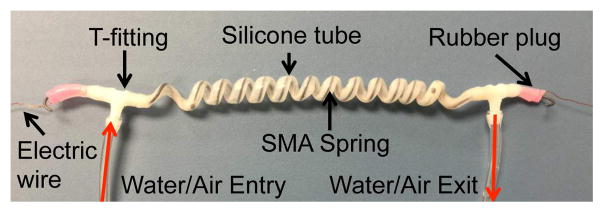
In this work, we attempt to address one particular issue with SMA, its slow response. An interesting prototype introduced by Mascaro and Asada in 2003 [26] was a wet actuator which was an SMA wire enclosed in a compliant tube that changed its longitudinal shape with the SMA when it was heated by flowing hot water through the tube. Cold water was then passed through the tube to cool the SMA wire and return the SMA to its low-stiffness martensite phase. Inspired by the idea and intending to apply it on SMA spring, we proposed a cooling module-integrated SMA spring [19]. It involves the threading of a flexible tube through the SMA spring and sealing of the two ends by rubber plugs, as shown in Fig. 1. For the idea to work well, the flexible tube needs to have the right amount of softness, flexibility, and wall thickness. Different from [19], where our idea was first introduced and tested, the current work involves rigorous selection process of the best available silicone tube (McMaster-Carr) to be used as the cooling module for the SMA spring of our choice (Flexmet, Belgium). Tubes with different parameters were tested on the SMA spring that has a spring coil diameter, Ds, of 6.5 mm and a wire diameter, ds, of 0.75 mm. Table I shows the different tubes that we attempted to use for the cooling channel of SMA spring [27]. We eventually chose Tube 6 because it has the best combination of inner diameter, softness, and wall thickness to ensure smooth water flow and prevent unnecessary stress on the SMA spring.
Fig. 1.
SMA spring actuator with integrated water cooling Module
TABLE I.
Tube Parameters
| Name | Inner Diameter (mm) | Outer Diameter (mm) | Wall Thickness (mm) | Softness (Shore A) |
|---|---|---|---|---|
|
| ||||
| Tube 1 (High Purity White Silicone Rubber Tubing (Non-reinforced)) | 1.02 | 2.16 | 0.58 | 55 |
| Tube 2 (Odor Resistant White Silicone Rubber Tubing) | 1.57 | 2.41 | 0.43 | 50 |
| Tube 3 (High Temperature NSF-51 Silicone Rubber Tubing) | 1.59 | 3.18 | 0.79 | 50 |
| Tube 4 (High Temperature Silicone Rubber Tubing) | 1.59 | 3.18 | 0.79 | 35 |
| Tube 5 (Laboratory Clear Tygon PVC Tubing) | 2.38 | 3.18 | 0.41 | 56 |
| Tube 6 (High Purity White Silicone Tubing) | 1.98 | 3.18 | 0.61 | 50 |
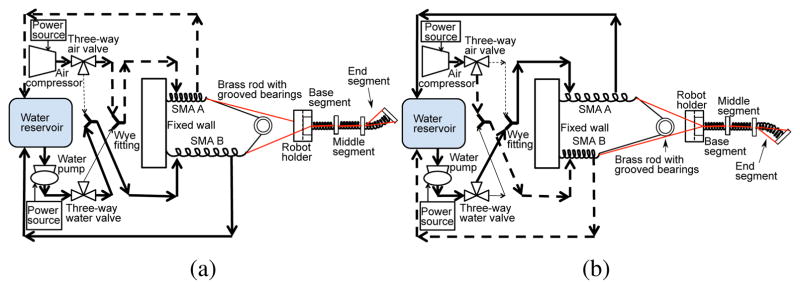
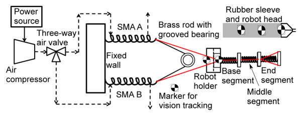
Different from our previous work [19], our newly proposed mechanism involves water as the cooling medium and compressed air as the medium to remove the water for efficient resistive heating. A fluid circulation system is developed to realize the mechanism, consisting of a water reservoir, an air compressor, wye fittings, and water and air valves for alternating the flow during the heating and cooling process. Each antagonistic pair of SMA springs (say, SMA A and SMA B) are responsible for only one DoF of a robot segment. Each SMA spring pair is connected directly to each other by a monofilament fishing line that is routed around a grooved bearing. Each individual SMA spring is also connected by the tendon driven mechanism to a hole terminated at a robot segment disk to bend it in one direction. Figs. 2(a) and 2(b) show the air and water flow during bending of a robot segment in two different directions. For example, in Fig. 2(b), air valves are opened for a short period of time (varies depending on the gauge pressure of the compressed air) to pass the compressed air at high pressure through the cooling module to force the static water out, thereby allowing water to return to the water reservoir and enabling more efficient subsequent heating. SMA B is at the same time, cooled by flowing water through its tube (water valve is opened), therefore providing minimum resistance to the upward bending of the robot.
Fig. 2.
Schematics showing water flow (bold solid line) and air flow (bold dashed line) during (a) upward motion and (b) downward motion of the middle segment
III. Actuator Characterization for Optimal Robot Speed
The new actuation mechanism applied on the cooling module-integrated SMA spring has to be characterized to determine the highest robot speed that can be achieved by MINIR-II. The characterization parameters are largely based on the heat transfer model that governs the SMA spring during its actuation. It can be expressed as follows [19]:
| (1) |
where Ts, βs, I, ρs, hf, Tf, Ls, ξ̇ and Cs are the surface temperature of SMA, SMA resistivity, current, SMA density, heat convection coefficient of fluid, fluid temperature, latent heat of transformation, rate of phase transformation, and specific heat capacity of SMA, respectively. Subscript ‘s’ denotes the SMA spring wire and subscript ‘ f ’ denotes the fluid in the coiled silicone tube, be it air, denoted by subscript ‘a’ (during the heating phase) or water, denoted by ‘w’ (during the cooling phase). The second term in Eq. (1) represents the power used for resistively heating the SMA spring. The third term describes the rate of heat transfer between the SMA spring and its environment (air during the heating phase and water during the cooling phase). Heat convection coefficient, hw, from Eq. (1), is defined as [28]:
| (2) |
where the hydraulic diameter can be expressed as Dh = dt – ds [28], and dt, ds, Nu and kf are the silicone tube inner diameter, SMA spring wire diameter, Nusselt number, and thermal conductivity of the fluid in the cooling module, respectively. The third term describes the rate of change in latent heat energy during phase transformation of SMA between the martensite phase and austenite phase.
The experimental variables that are derived from the three heat transfer model parameters are the current, water flow rate, and pre-displacement of the SMA springs. We also investigated the effect of gauge pressure of the compressed air due to the mechanism we used in circulating the fluid. During each characterization experiment, we actuated the end segment of the robot in one DoF for ±10° and varied only one parameter while keeping the other parameters constant. Our control parameter combination is as follows: current = 3.5 A; water flow rate = 1150 mm3/s; pre-displacement = 50 mm; and gauge pressure = 15 psi.
A. Effect of current
Since current is used to vary the power, we used a motor driver in its current controller mode for heating the SMA spring. The upper limit of the current was set to be 3.8 A to prevent excessive heating in the electrical wire as well as difficulty in controlling actuation over a small range of motion in the robot joint. Four different currents were applied to the SMA springs, namely: 3.0 A, 3.25 A, 3.5 A and 3.8 A.
Eq. (1) provides us with the theoretical prediction of the change in the SMA temperature when it gets heated. For free convection (air is static in the silicone tube during the SMA heating phase), we applied the equation for Nusselt number based on [31], suitable for fluids of a large range of Raleigh number (Ra). Thus,
| (3) |
where . Pr, βa, νa, and αa are the Prandtl number, volumetric coefficient of thermal expansion, kinematic viscosity, and thermal diffusivity, respectively, of air. Using Eq. (3) and referring to Table II, heat convection coefficient during the heating phase, ha, can be calculated through Eq. (2).
TABLE II.
Heat Transfer Parameters
| Parameters | Symbols | Units | Values |
|---|---|---|---|
| SMA spring wire | |||
| Wire diameter | ds | m | 0.75 × 10⁻³ |
| Coil diameter | Ds | m | 6.5 × 10⁻³ |
| Resistivity | βs | μΩ·m | 0.44 |
| Density | ρs | kg/m3 | 6450 [29] |
| Thermal conductivity | ks | W/(m·K) | 18 [30] |
| Specific heat capacity | Cs | J/(kg·K) | 466 (heating) −260 (cooling) |
| Latent heat (heating) | Lsh | J/kg | 12188.1 |
| Latent heat (cooling) | Lsc | J/kg | −4137.6 |
| Air | |||
| Temperature | Ta | K | 300 |
| Thermal conductivity | ka | W/(m.K) | 0.0263 |
| Expansion coef. | βa | 1/K | 3.43 × 10⁻³ |
| Kinematic viscosity | νa | m2/s | 15.89 × 10⁻⁶ |
| Thermal diffusivity | αa | m2/s | 22.5 × 10⁻⁶ |
| Water | |||
| Temperature | Tw | K | 300 |
| Prandtl number | Pr | - | 5.83 |
| Thermal conductivity | kw | W/(m.K) | 0.613 |
| Kinematic viscosity | νw | m2/s | 8.6 × 10⁻⁷ |
B. Effect of water velocity
Forced convection happens as the water is continuously flown through the tube to cool the SMA spring. For forced convection, the following equation was implemented in our thermal model [32]:
| (4) |
Re is given by , where uw and νw are the velocity and kinematic viscosity of water, respectively. Water velocity, uw can be related to its flow rate, qw through . Therefore, in our characterization experiments, we implemented five different water flow rates: 800 mm3/s, 1000 mm3/s, 1150 mm3/s, 1330 mm3/s, and 1500 mm3/s.
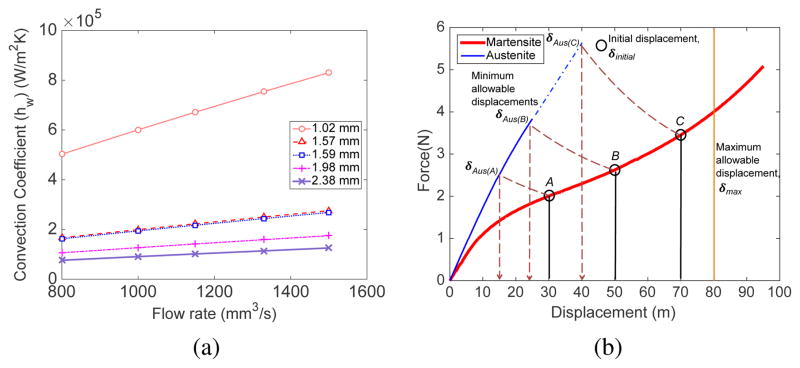
Using Eq. (2) and Eq. (4), and referring to Table II, theoretical heat convection coefficient, hw, is plotted against various tube inner diameters, dt, that were selected in Table I for different flow rates, qw. The results are plotted in Fig. 3(a). Under the ideal condition that the SMA spring wire is always in the center of the tube and there is uniform flow around the SMA spring wire, the convection coefficient increases with an increase in the water flow rate and a decrease in the tube diameter. However, a tube diameter of 1.98 mm was chosen because it is the smallest tube diameter that allows water to flow smoothly during the contraction of the SMA spring.
Fig. 3.
(a) Predicted heat convection coefficient with variation in the tube inner diameter and water flow rate (b) Theoretical relationship to determine SMA pre-displacement, δinitial, to ensure coverage of the desired motion range
C. Effect of pre-displacement
Pre-displacements of the antagonistic SMA springs are identical to ensure that the robot joint can be actuated in either direction for the same angular displacement. The graph, shown in Fig. 3(b), explains how the antagonistic SMA springs in our setup theoretically behave. The characteristic martensite (red curve in Fig. 3(b)) and austenite (blue curve in Fig. 3(b)) curves were experimentally determined by stretching (within recoverable limit) the SMA spring at room temperature (Ts ≤ AS) and at Ts ≥ AF, respectively while recording its displacement and force, where AS and AF are the austenite start and austenite finish temperatures. The maximum SMA recovery length was experimentally determined to be 80 mm [19]. The figure shows three cases of initial SMA displacement: δinitial(A), δinitial(B), and δinitial(C). The heated (contracting) SMA spring follows the dotted line and moves towards the austenite curve from its initial displacement while the non-heated SMA spring, getting extended, moves towards the right by following the characteristic martensite curve from the initial displacement. The path taken by the heated SMA spring is a mirror image of that by the non-heated SMA spring. The maximum range of motion in case A is dictated by the displacement of the heated spring that contracts to 15 mm (δAus(A)) while that in case C is dictated by the displacement of the non-heated spring, which is only 10 mm away from the maximum allowable displacement of SMA. To ensure the maximum range of motion in each direction, the optimal pre-displacements should be around 50 mm.
Secondly, phase transformation in the SMA spring is affected by its stress level [33] and pre-displacement can hypothetically be optimized to improve the rate of SMA temperature and its phase transformation, and thus the robot motion speed. Three SMA pre-displacements were considered in the characterization experiment, namely: 35 mm, 50 mm, and 65 mm. Using the experimentally measured force, theoretical temperature profile for each SMA pre-displacement is determined through Eq. (1) and compared with the experimental data in section V.
D. Effect of gauge pressure
We used compressed air to drive the water out so that the power supplied to the SMA can be primarily used for heating the SMA instead of heat dissipation in the surrounding water. To optimize the actuation mechanism, the air valve should be shut off as soon as the heating phase takes over. The fluid motion between the air valve opening and the outlet at the end of the coiled tube is modeled in order to predict the theoretical duration for which air valve needs to be turned on. Since the air passes through a straight tube with 1.5 m length before entering the coiled cooling module, the total pressure loss (gauge pressure) can be expressed as follows [34]:
| (5) |
where ΔPfs, ΔPfc, and ΔPa are the frictional component in the straight section of the tubing, the frictional component in the coiled cooling module, and the acceleration components, respectively and can be expressed as , and . fs and fc are the friction factors in the straight tube and the coiled cooling module, respectively while Ls and Lc are the lengths of the straight tube and the coiled cooling module, respectively. The flow investigated in our case are considered laminar in the straight tube since the Reynolds number (Re) is less than the critical value of 2100 [35]. The critical Re used to distinguish laminar and turbulent flow in coiled cooling module can be determined from [36]: . The reynolds numbers of the flow in the coiled tube for all flow rates investigated are much less than the critical value of 16008. Therefore it is confirmed that the flow throughout the entire tubing system is laminar. Friction factor in the straight tube can be expressed as [35] whereas that in the coiled tube can be expressed as fc = fs(0.556+0.0969(Dn))[36]. The Dean number is defined as . Using the water velocities experimentally measured at different gauge pressures and solving Eq. (5), we obtain the time required to remove water from the coiled cooling module at different gauge pressure of the compressed air through .
The theoretical and experimental time required for the water to be completely removed from the cooling module were compared and an average error of 0.53 s was observed. The experimentally measured times of 3.5 s, 2.3 s, 1.8 s, 1.5 s, and 1.3 s were then hardcoded into the control program to determine the duration for which the compressed air is turned on in the characterization experiments for the five different gauge pressures of 5 psi, 10 psi, 15 psi, 20 psi and 25 psi, respectively.
IV. Experimental Setup
A. Robot
Our continuum robot consists of an inter-connected spring, a flexible rubber sleeve, and a robot head with channels for cautery probes, suction tube and magnetic field sensor (Robin Medical Inc., Baltimore, USA), as shown in Fig. (4). The inter-connected spring backbone is divided into three segments, namely base, middle and end segments, each of which consists of a disk and a spring. The design is an improved version of our MINIR-II prototype [2] as it now has a larger lumen to incorporate cable for the magnetic field sensor. The design is constrained by the largest diameter of 12 mm so that the robot can fit into existing endoports used in microsurgery of brain tumor as well as the minimum lumen diameter of 4 mm for the passing of sensor cable, tendons, cautery probe wires, and suction tube. After multiple trials, the robot is determined to have optimal stiffness (defined by its ability to maintain its elasticity after at least a 90° angular displacement of the surface normal of the segment disk without breaking) with a spring wire diameter of 1.4 mm, a spring mean diameter of 5.2 mm, and 1.5 mm pitch. The robot is experimentally determined to have a bending stiffness of 8.7 N/m whereas a single segment has a bending stiffness of 96 N/m. The prototype is rapid prototyped by Shapeways using the Frosted Extreme Detail material, which has a tensile modulus of 1463 MPa and a flexural strength of 49 MPa.
Fig. 4.
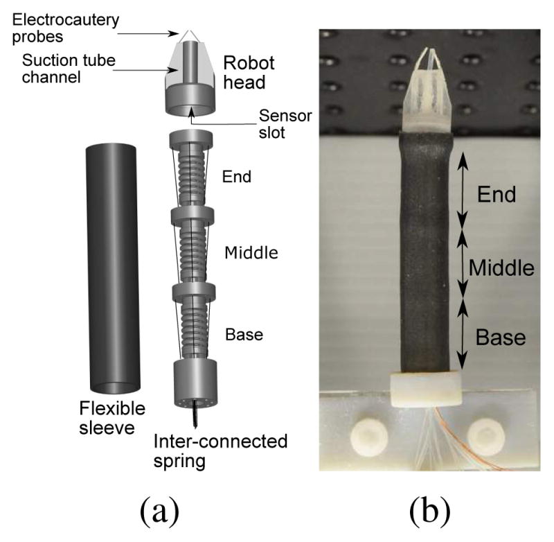
(a) Schematics of the inner spring with three segments, rubber sleeve, and the robot head (b) Fully assembled MINIR-II prototype
The outer spring in our previous prototype [2] is replaced by a flexible sleeve that continues to separate the tendons from the environment but provides the additional advantage of a waterproof interface to protect the magnetic field sensor. The sleeve is rapid prototyped using Stratasys Object500 Connex 3 from the TangloBlackPlus FLX980 material, that can sustain approximately 200% elongation and has a tensile strength of 115–220 MPa. The current design retains the advantages of smooth shape change and a compliant interface of our previous prototype. Tendon-driven mechanism is again employed so that the main robot body does not have to house any actuators and the heating of SMA would not cause distortion in the MR images. Each robot segment has two pairs of tendons terminated at its corresponding disk that would produce two-DoF bending. The central tendon routing configuration is used in the current robot to allow independent segment control [2].
B. Experiment
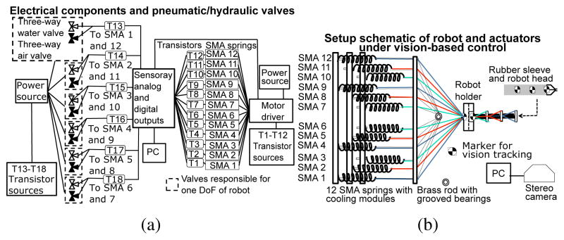
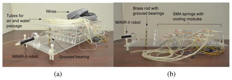
We envision that the MINIR-II will be controlled under real-time MR image feedback. Since we are not using MR images at this point to control the robot motion, we implemented a vision-based control using a stereo camera to use the camera images as feedback to evaluate the performance of our 6 DoF robot. The schematic of the entire robotic system is shown in Fig. 5. The actuator platform is manufactured from laser cut acrylic plates, as shown in two different viewpoints in Figs. 6(a) and 6(b). For actuating twelve SMA springs which control three robot segments, we use six water valves and six air valves. Twelve transistors are used to determine the SMA spring actuator that would be heated by the motor driver (power source). A brass rod with three grooved plastic bearings are used, as seen in Figs. 6(a) and 6(b), to provide a direct connection between each antagonistic pair of SMA springs for each DoF. This is an important feature of the SMA actuation system for this spring-based flexible robot to prevent it from getting compressed due to the unexpected tension in the SMA springs. In this way, the non-heated SMA spring always applies zero tension on the robot segment. The entire experimental setup consists of a water reservoir, twelve three-way valves (12V DC Solenoid Valve, Electricsolenoidvalves.com, New York, USA), an actuator platform with twelve SMA spring actuators and the robot, an air compressor, an Analog/Digital Input/Output board (Model 826, Sensoray, USA), and a vision camera (MicronTracker, Claron Technology Inc., Canada).
Fig. 5.
(a) Electrical and pneumatic/hydraulic components involved in the experimental setup (b) Schematic of vision-based experimental setup for actuating 6 DoFs of MINIR-II
Fig. 6.
(a) Robot platform with the spring-based robot, twelve cooling module-integrated SMA springs and tubes (b) Side view of the robot platform made out of laser-cut acrylic
We used vision markers of 8 mm diameter to allow accurate tracking of each robot joint. The four markers (in the same plane) were respectively attached to the base of the robot, the end of the base segment, the end of the middle segment, and the robot tip. A virtual vector is formed between two adjacent markers and the angle subtended by two vectors determines the angular displacement of the corresponding robot segment. The angular displacement was considered as the vision feedback variable in this active vision control system and Proportional+Integral (PI) control was implemented to achieve set point tracking. We used the robot platform and vision-based control to perform all the characterization experiments for different control parameters as well as the experiments that compare the robot performance under forced water and forced air cooling for four motion amplitudes, namely ±5°, ±10°, ±15°, and ±20°. Two force sensors are added to the experimental setup to measure the force exerted by each of the two SMA springs that are in antagonistic configuration.
In the characterization experiments, we varied one parameter and kept the other parameters at the control state. Step inputs of ±10° were applied to the end robot segment. The same experimental setup, as shown in Fig. 6, was used during the forced air cooling experiment, except that the water reservoir and valves used for flowing water were removed. Compressed air (high speed air), maintained at gauge pressure of 25 psi, instead act as the cooling medium during the experiment. The schematic for the forced air cooling setup is shown in Fig. 7.
Fig. 7.
Schematic of the experimental setup that uses compressed air to force cool one pair of SMA springs for one- DoF motion of the end segment
V. Results and Discussion
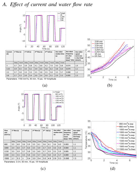
In all the characterization experiments, a target amplitude of 10° angular displacement of the robot was implemented and the end robot segment was actuated. The raw data of angular displacement vs time is plotted in the characterization graphs while the important information from the graphs are analyzed and collected in the table under each graph. Delay time is the time it takes for the robot (not the SMA spring) to start moving after the control signal is provided to heat the SMA spring. Travel time is the time it takes for the robot to move to the target amplitude and can either be rise time or fall time. The robot frequency is defined as the reciprocal of the total time required to travel to a target amplitude (rise time) and back (fall time). The average robot speed is calculated by multiplying the distance traveled by the robot tip in a complete motion cycle, which covers one rise and one fall time, with the average robot frequency. The exact distance traveled by the robot tip is stated in each table. The parameters implemented in the experiment are clearly stated under each table. It should be noted that only the robot motion data between 30 s and 110 s is considered in the analysis. Overall, the robot speed achieved under the new actuation mechanism is more than 1 mm/s, which is within the 0.5 mm/s–5 mm/s range reported in the literature. Besides the robot displacement that was tracked by the vision camera, temperature of the SMA spring was also recorded and is discussed and compared with the model for characterization parameters such as current, water flow rate and pre-displacement.
A. Effect of current and water flow rate
As shown in Fig. 8(a), higher current reduces both the average delay time and travel time and the robot achieved an average robot speed of 1.3 mm/s at 3.8 A. As shown in Fig. 8(b), our model has produced matching temperature behavior as the experiment for each current, especially in terms of the rate of change of temperature (overall slope) and the final temperature.
Fig. 8.
Robot motion in response to step input at various (a) currents and (b) water flow rates. Temperature change in response to step input at various (c) currents and (d) water flow rates
According to analysis in Fig. 8(c), the average delay times and average robot speed for the water flow rates of 800 mm3/s, 1000 mm3/s, and 1150 mm3/s are very similar and improved significantly under the two highest flow rates. As shown in Fig. 8(d), the experimental temperature profiles for the two highest flow rates are especially steep, allowing the resisting SMA spring to reach the martensite finish temperature sooner. Using the theoretical heat coefficients calculated in Fig. 3(a) for 1.98 mm tube diameter, which are 1.06×10⁵ W/m2K, 1.27×10⁵ W/m2K, 1.42×10⁵ W/m2K, 1.59×10⁵ W/m2K, and 1.75×10⁵ W/m2K for water flow rates of 800 mm3/s, 1000 mm3/s, 1150 mm3/s, 1330 mm3/s, and 1500 mm3/s, respectively, the model proves to produce consistent temperature profiles as the experimental data. The discrepancies in the initial cooling stage and the final settling temperature for certain flow rates could be a result of the rough experimental force data used in the model and the imperfect bond between the temperature sensor and the SMA spring.
B. Effect of pre-displacement and gauge pressure
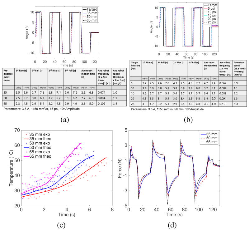
The pre-displacement characterization results, shown in Fig. 9(a), show that the robot average speed improves with larger SMA spring pre-displacement. This can be explained by the highest SMA heating rate and output force increase rate when it is pre-stretched by the most, as shown in Figs. 9(c) and 9(d). The delay time, however, does not show a consistent trend. According to the works of Tanaka [33], Brinson [37] and more recent works by Li et al: [38], higher stress in the SMA increases its transformation temperatures. Our experiment matches the theory only for the SMA spring with the smallest pre-displacement (35 mm) as it produced the shortest delay time, likely due to the SMA spring reaching its relatively lowest austenite start temperature quickest and starting to contract the soonest. One explanation for the inconsistent trend with the next two pre-displacements is that the higher heating rate of the SMA with the largest pre-displacement made up for its highest austenite start temperature. This allows the SMA with 65 mm pre-displacement to have less delay time than that with 50 mm pre-displacement. Figure 9(d) shows the net force exerted on the robot by the SMA springs in antagonistic configuration. The SMA with the largest pre-displacement exerted the largest force in the shortest amount time of time.
Fig. 9.
(a) Robot motion in response to step input at various SMA pre-displacements and (b) gauge pressures (c) Temperature change during one heating phase due to different pre-displacements (d) Net force acting on the robot in response to step inputs at various pre-displacements
As shown in Fig. 9(b), clear distinction in the robot speed was observed for different gauge pressures. The highest gauge pressure led to the fastest elimination of the water in the cooling module and therefore more efficient heating was initiated earlier.
C. Comparison between two cooling media: Water and Air
We investigated the effect of different cooling media on the robot speed at four motion amplitudes. The average robot speed when water was the cooling medium consistently more than doubled that when high speed compressed air was used, as shown in Table III. There is however only slight difference in the delay time. The robot speed also improves under both cooling media when the motion amplitude becomes larger and it reaches 1.73 mm/s under forced water cooling at amplitude of 20°. This is due to the non-linear SMA heating behavior with smaller initial heating slope.
TABLE III.
Performance comparison between water (our proposed mechanism) and air for different motion amplitudes
| Cooling medium | Average | Robot | Speed | (mm/s) |
|---|---|---|---|---|
| 5° | 10° | 15° | 20° | |
| Water | 0.82 | 1.28 | 1.42 | 1.73 |
| Air | 0.34 | 0.53 | 0.68 | 0.80 |
VI. Conclusion
We have developed an SMA spring-actuated robotic system with active water cooling to enable real-time control of SMA spring actuators. Due to the limitation in actuation bandwidth of the SMA material, we implemented a new actuation mechanism to operate the previously developed cooling module-integrated SMA springs. Water is used as the coolant during the cooling phase and compressed air as the medium to force out water during the heating phase. We modeled the thermal behavior of the SMA spring that is operated under the new mechanism at different currents, water flow rates, and SMA pre-displacements. Gauge pressure of the compressed air is another important control parameter to optimize the robot speed. Experimental characterization was performed to determine the effect of each parameter on the robot speed and experimental data was used to verify the model. Comparison between water and air as the cooling media also demonstrates that water consistently provides superior performance in terms of the robot speed. Our new actuation mechanism has been shown to allow the robot to consistently achieve average robot speed of more than 1mm/s, which is within the speed range reported in literature for neurosurgical robots. The results from the current work serve as important foundation for the tuning of the control parameters especially when the robot is tested in the brain tumor in a cadaver.
Acknowledgments
Research reported in this publication was supported by the National Institute Of Biomedical Imaging And Bioengineering of the National Institutes of Health under Award Number R01EB015870. The content is solely the responsibility of the authors and does not necessarily represent the official views of the National Institutes of Health.
References
- 1.Brain tumor statistics. [Online] Available: http://www.abta.org/aboutus/news/brain-tumor-statistics/
- 2.Kim Y, Desai JP. Design and kinematic analysis of a neurosurgical spring-based continuum robot using SMA spring actuators. Proceedings of the IEEE/RSJ International Conference on Intelligent Robots and Systems (IROS 2015); 2015. [Google Scholar]
- 3.Bajo A, Simaan N. Kinematics-based detection and localization of contacts along multisegment continuum robots. IEEE Transactions on Robotics. 2012 Apr;28(2):291–302. [Google Scholar]
- 4.Choi DG, Yi BJ, Kim WK. Design of a spring backbone micro endoscope. Proceedings of the IEEE/RSJ Intelligent Robots and Systems (IROS 2007); 2007. pp. 1815–1821. [Google Scholar]
- 5.Ataollahi A, Karim R, Soleiman Fallah A, Rhode K, Razavi R, Seneviratne L, Schaeffter T, Althoefer K. 3-DOF MR-compatible multi-segment cardiac catheter steering mechanism. 2013 doi: 10.1109/TBME.2013.2276739. [DOI] [PubMed] [Google Scholar]
- 6.Su H, Cardona DC, Shang W, Camilo A, Cole G, Rucker DC, Webster RJ, Fischer GS. A MRI-guided concentric tube continuum robot with piezoelectric actuation: a feasibility study. Proceedings of the IEEE International Conference on Robotics and Automation (ICRA 2012); 2012. pp. 1939–1945. [Google Scholar]
- 7.Yang B, Roys S, Tan U-X, Philip M, Richard H, Gullapalli RP, Desai JP. Design, development, and evaluation of a masterslave surgical system for breast biopsy under continuous MRI. The International Journal of Robotics Research. 2013 doi: 10.1177/0278364913500365. [DOI] [PMC free article] [PubMed] [Google Scholar]
- 8.Kim B, Lee S, Park JH, Park JO. Design and fabrication of a locomotive mechanism for capsule-type endoscopes using shape memory alloys (SMAs) IEEE/ASME Transactions on Mechatronics. 2005;10(1):77–86. [Google Scholar]
- 9.Ayvali E, Liang CP, Ho M, Chen Y, Desai JP. Towards a discretely actuated steerable cannula for diagnostic and therapeutic procedures. The International journal of robotics research. 2012;31(5):588–603. doi: 10.1177/0278364912442429. [DOI] [PMC free article] [PubMed] [Google Scholar]
- 10.Sheng J, Desai JP. Towards a SMA-actuated neurosurgical intracerebral hemorrhage evacuation (NICHE) robot. Intelligent Robots and Systems (IROS), 2015 IEEE/RSJ International Conference on; IEEE; 2015. pp. 3805–3810. [Google Scholar]
- 11.Ho M, Kim Y, Cheng SS, Gullapalli R, Desai JP. Design, development, and evaluation of an MRI-guided SMA spring-actuated neurosurgical robot. The International Journal of Robotics Research. 2015 doi: 10.1177/0278364915579069. [DOI] [PMC free article] [PubMed] [Google Scholar]
- 12.Anderson W, Chapman C, Karbaschi Z, Elahinia M, Goel V. Design and testing of a minimally invasive intervertebral cage for spinal fusion surgery. Smart Structures and Systems. 2013;11(3):283–297. [Google Scholar]
- 13.Andani MT, Bucchi F, Elahinia MH. SMA actuation mechanisms. Shape Memory Alloy Actuators: Design, Fabrication and Experimental Evaluation. 2015:85. [Google Scholar]
- 14.Louw DF, Fielding T, McBeth PB, Gregoris D, Newhook P, Sutherland GR. Surgical robotics: A review and neurosurgical prototype development. Neurosurgery. 2004;54(3) doi: 10.1227/01.neu.0000108638.05274.e9. [DOI] [PubMed] [Google Scholar]
- 15.Comparetti M, De Momi E, Vaccarella A, Riechmann M, Ferrigno G. Optically tracked multi-robot system for keyhole neurosurgery. Proceedings of the IEEE International Conference on Robotics and Automation (ICRA 2011); May 2011; pp. 661–666. [Google Scholar]
- 16.De Lorenzo D, De Momi E, Dyagilev I, Manganelli R, Formaglio A, Prattichizzo D, Shoham M, Ferrigno G. Force feedback in a piezoelectric linear actuator for neurosurgery. The International Journal of Medical Robotics and Computer Assisted Surgery. 2011;7(3):268–275. doi: 10.1002/rcs.391. [DOI] [PubMed] [Google Scholar]
- 17.Godage IS, Remirez AA, Wirz R, Weaver KD, Burgner-Kahrs J, Webster RJ., III Robotic intracerebral hemorrhage evacuation: An in-scanner approach with concentric tube robots. Intelligent Robots and Systems (IROS), 2015 IEEE/RSJ International Conference on; IEEE; 2015. pp. 1447–1452. [Google Scholar]
- 18.Fukami N. Endoscopic Submucosal Dissection: Principles and Practice. Springer; 2015. [Google Scholar]
- 19.Cheng SS, Desai JP. Towards high frequency actuation of SMA spring for the neurosurgical robot-MINIR-II. Proceedings of the IEEE International Conference on Robotics and Automation (ICRA 2015); May 2015; pp. 2580–2585. [Google Scholar]
- 20.Lewis N, York A, Seelecke S. Experimental characterization of self-sensing SMA actuators under controlled convective cooling. Smart Materials and Structures. 2013;22(9):094012. [Google Scholar]
- 21.Zhang L, Hu G, Wang Z. Study on liquid-jet cooling and heating of the moving SMA actuator. International Journal of Thermal Sciences. 2008;47(3):306– 314. [Google Scholar]
- 22.Russell RA, Gorbet R. Improving the response of SMA actuators. Proceedings of the IEEE International Conference on Robotics and Automation (ICRA 1995); May 1995; pp. 2299–2304. [Google Scholar]
- 23.Kim Y, Cheng SS, Ecins A, Fermüller C, Westlake KP, Desai JP. Towards a robotic hand rehabilitation exoskeleton for stroke therapy. Proceedings of ASME 2014 Dynamic Systems and Control Conference; October 22–24 2014.ASME; [Google Scholar]
- 24.Chee Siong Loh TA, Yokoi Hiroshi. Natural heat-sinking control method for high-speed actuation of the SMA. International Journal of Advanced Robotic Systems. 2006;3(4) [Google Scholar]
- 25.Pathak A, Brei D, Luntz J. Experimental characterization of the convective heat transfer from shape memory alloy SMA wire to various ambient environments. International Conference on Adaptive Structures and Technologies (ICAST 2008); Ascona, Switzerland. October 6–9 2008; p. 12. [Google Scholar]
- 26.Mascaro SA, Asada HH. Wet shape memory alloy actuators for active vasculated robotic flesh. Robotics and Automation, 2003. Proceedings. ICRA’03. IEEE International Conference on; IEEE; 2003. pp. 282–287. [Google Scholar]
- 27.Cheng SS, Kim Y, Desai JP. Towards real-time SMA control for a neurosurgical robot: MINIR-II. Proceedings of the International Symposium on Robotics Research (ISRR 2015); 2015. in press. [Google Scholar]
- 28.Incropera FP. Fundamentals of Heat and Mass Transfer. John Wiley & Sons; 2006. [Google Scholar]
- 29.Technical Characteristics of FLEXINOL Actuator Wires,” Dynalloy. Technical note. 2011 Nov; [Online]. Available: http://www.dynalloy.com/TechSheets.php.
- 30.Ertel J, Mascaro S. Dynamic thermomechanical modeling of a wet shape memory alloy actuator. Journal of Dynamic Systems, Measurement, and Control. 2010;132:45–57. [Google Scholar]
- 31.Churchill SW, Chu HH. Correlating equations for laminar and turbulent free convection from a horizontal cylinder. International Journal of Heat and Mass Transfer. 1975;18(9):1049– 1053. [Google Scholar]
- 32.Fand R, Keswani K. The influence of property variation on forced convection heat transfer to liquids. International Journal of Heat and Mass Transfer. 1972;15(8):1515– 1536. [Google Scholar]
- 33.Tanaka K. A thermomechanical sketch of shape memory effect: One-dimensional tensile behavior. Res Mechanica. 1986;18(3):251–263. [Google Scholar]
- 34.Rao B. Technical note. Coiled tubing hydraulics modeling,” CTES. [Google Scholar]
- 35.Ryan N, Johnson M. Transistion from laminar to turbulent flow in pipes. AIChE Journal. 1959;5(4):433–435. [Google Scholar]
- 36.Srinivasan P, Nandapurkar S, Holland F. Friction factors for coils. Trans Inst Chem Eng. 1970;48(4–6):T156–T161. [Google Scholar]
- 37.Brinson L. One-dimensional constitutive behavior of shape memory alloys: Thermomechanical derivation with non-constant material functions and redefined martensite internal variable. Journal of Intelligent Material Systems and Structures. 1993;4(2):229–242. [Google Scholar]
- 38.Li Y, Cui L, Shi P, Yang D. Phase transformation behaviors of prestrained TiNi shape memory alloy fibers under the constraint of a hard substrate. Materials Letters. 2001;49(3):224–227. [Google Scholar]


