Abstract
In this work, a non-reflective boundary condition, the Perfectly Matched Layer (PML) technique, is adapted and implemented in a fluid-structure interaction numerical framework to demonstrate that proper boundary conditions are not only necessary to capture correct wave propagations in a flow field, but also its interacted solid behavior and responses. While most research on the topics of the non-reflective boundary conditions are focused on fluids, little effort has been done in a fluid-structure interaction setting. In this study, the effectiveness of the PML is closely examined in both pure fluid and fluid-structure interaction settings upon incorporating the PML algorithm in a fully-coupled fluid-structure interaction framework, the Immersed Finite Element Method. The performance of the PML boundary condition is evaluated and compared to reference solutions with a variety of benchmark test cases including known and expected solutions of aeroacoustic wave propagation as well as vortex shedding and advection. The application of the PML in numerical simulations of fluid-structure interaction is then investigated to demonstrate the efficacy and necessity of such boundary treatment in order to capture the correct solid deformation and flow field without the requirement of a significantly large computational domain.
1. Introduction
Numerical simulations of wave propagating in fluids often require appropriate boundary treatments. Appropriate treatment of the numerical boundary is crucial to accurately simulate flow-related problems in partially or fully unbounded fields without requiring excessive representation of the large field. An untreated or improper numerical boundary condition often cause spurious reflections from outgoing waves, which can severely contaminate the physical flow field. Problems involving interactions between propagating waves and deformable solids may see further impact of an untreated numerical boundary.
There has been extensive development on techniques proposed to properly address the aforementioned boundary conditions [1, 2, 3], such as a so-called do-nothing boundary condition [4], infinite element method [5, 6], Dirichlet-to-Neumann radiation condition [7, 8], and various non-reflective boundary conditions (NRBCs) [2, 9, 10, 11]. The last category, NRBCs, is frequently used and implemented with the benefit of retaining computational efficiency of numerical methods [12]. Some earlier efforts have been committed to truncate unbounded fields with NRBCs based on method of characteristics [13, 14] and Navier-Stokes characteristic outflow boundary conditions [15, 16]. However, the intended “non-reflectiveness” has not been ideal due to the non-optimal absorption of waves with oblique angles [17]. Other attempt for treating in particular large Reynolds number flows has also been proposed [18], however it was strictly for incompressible flows, more developments are necessary to study aeroelastic wave propagations.
A relatively novel and more robust NRBC approach is the Perfectly Matched Layer (PML) technique, initially proposed and formulated by Bérenger to solve unbounded electromagnetic problems with finite-difference time-domain method solution of Maxwell’s equations [19, 20, 21]. It has since been developed and evolved for applications of various other differential equations including Euler and Navier-Stokes equations [2, 22, 23]. One major advantage of PML comparing to many other NRBC methods is that the absorption is effective for multi-dimensional waves and flows of all incidence angles, and theoretically of all frequencies [12, 17, 19]. The PML technique can be plainly interpreted either as a complex change of variables in the frequency domain [22], or as a coordinate transformation that maps the original real coordinate onto a complex domain, where the physical domain is separated from the imaginary component that represents the PML. Within the PML domain, the continuing wave is “forced” to decay exponentially [24, 25, 26].
While much attention has been focused on the development of the PML technique and its application on Navier-Stokes equations [1, 2, 17, 22, 23], few applications are related to fluid-structure interaction problems. Studies that focused on fluid-structure interactions with non-reflective boundary condition mostly involve simplified models for either the structure or the flow, such as coupling the blood flow to a simplified 1D flow model in hopes to reduce spurious reflections with relatively generous tolerance for its effectiveness [27, 28, 29].
The objective of this work is to investigate the effectiveness of PML in the environment of a high-fidelity fully-coupled fluid-structure interactions framework. The goal is to demonstrate and assess that an improper boundary treatment, e.g. untreated boundary, may not only affect the flow field and any wave propagation in a computational domain, but also greatly impact the solid motion, which then further impact the flow and propagation of the wave as time progresses. The error may ‘snowball’ as a result of the untreated boundary, which ultimately cause inaccuracy and divergence of the coupled solution. The fluid-structure interaction framework used in this work is the Immersed Finite Element Method (IFEM) [30, 31], which we have developed in the past decades. It is a technique proven to be accurate and efficient in simulating fully-coupled fluid-structure interactions. The fully-coupled scheme which is often referred to as strong coupling is essential in this context so that the correct propagation of fluid waves could have an instantaneous response in its interacted solid. On the contrary, a typical one-way coupling technique often fails to capture such feedback, which makes it challenging to distinguish the errors induced by the wave propagation due the boundary treatment and the errors induced from a delayed coupled response. Moreover, the immersed framework involves independent fluid and solid solvers, where the solid is entirely immersed in a fluid domain. Therefore, including PML in the fluid solver does not require any change in the coupling scheme. Through a series of numerical examples, this study shows the feasibility and effectiveness of PML in both pure fluid and fluid-structure interaction settings.
The paper is organized as follows: we first review the basic concept of the PML within the framework of the immersed finite element method in Section 2. As mentioned earlier, since the PML is to control the fluid domain boundary rather than the solid, in the immersed framework the PML implementation is only applied to the fluid equations. In order to also capturing aeroacoustic waves, the fluid is modeled as a slightly-compressible isentropic flow, mostly used to describe aeroacoustic waves with low Mach numbers. In Section 3, numerical studies of fluid dynamics and fluid-structure interaction test cases are presented to illustrate the effectiveness of the PML. Finally, concluding remarks are presented in Section 4.
2. Formulations
2.1. Perfectly Matched Layer
The Perfectly Matched Layer (PML) technique is essentially an absorbing boundary condition to sponge up any outgoing waves. The process is to make the waves reaching the numerical domain boundary so small that any resultant spurious reflections would be proportionally insignificant. As a result, the PML allows the truncation of physical domains without the implication of solutions being contaminated by spurious reflections at the boundaries [32, 33, 22].
A straightforward way to understand the PML methodology is to think of it as a specially designed complex domain. The complex domain z can be designed so that the wave magnitude at the intended numerical domain region is significantly attenuated. Generally for a sinusoidal wave with a wave number k and an angular frequency ω, we can express it analytically as:
| (1) |
where A is the amplitude of the wave, and t denotes time. The wave w(x, t) is a right-traveling wave, assuming that both k and ω are positive, and has a propagation speed of c = ω/k.
The same wave can also be considered in a complex domain z = x + if(x), rather than on the real domain x, in which x = Re(z) and f(x) = Im(z). Thus the wave equation on the complex domain z becomes:
| (2) |
The induced term e−kf(x) is considered as an attenuation factor of the original wave. In the physical domain, f(x) = 0 is set to yield e−kf(x) = 1, which results in the original real domain unaltered and brings no attenuation effects in the propagating wave. In contrast, we set the imaginary part of f(x), or the PML region, to be a positive value so that the attenuation factor e−kf(x) ≪ 1. Consequently, the wave amplitude can be significantly reduced in the PML region where Ae−kf(x) ≪ A, given that f(x) is sufficiently large. The boundary condition applied on the PML boundary is thus trivial as the amplitudes of spurious reflections are significantly small.
When using PML on partial differential equations describing physical phenomena, such as the Navier-Stokes equations for fluid dynamics and Maxwell’s equations for electromagnetism, the spatial derivatives of the aforementioned complex coordinate transformation are also required, where it is necessary to replace ∂xi with to describe physics on the artificially designed complex domain zi. It is worth mentioning that linearity is one of the underlying assumptions of the perfect matching theory, which makes the PML for the nonlinear Navier-Stokes equations not formally perfectly matched as discussed in Ref.[22].
An illustration is shown in Figure 1(a) where a 1-D complex domain z includes a physical (real) domain x ∈ [0, 5) and a PML (imaginary) region x ∈ [5, 10]. The corresponding f(x) = Im(z) is 0 in the physical domain and is set to increase linearly from f(5) = 0 to f(10) = 1 within the PML region. The red dashed line demarcates the physical domain on its left from the PML domain on its right. Figure 1(b) shows that a sinusoidal wave with a wave number k = 2π retains its waveform in the physical domain, yet is increasingly attenuated in the PML domain as the imaginary part f(x) = Im(z) increases. The corresponding attenuation factor at the right boundary x = 10 is e−kf(10) ≈ 0.0019, which reduces the wave magnitude by more than 500 times at the end of PML region. The resulting wave at the end of the entire computational domain is so small by the time it travels through the PML that its reflection is considered negligible.
Figure 1.
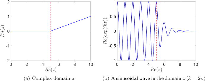
Illustration of wave attenuation on a complex domain.
As shown in Equation (2), the attenuation factor e−kf(x) has a dependency on the wave number k and therefore on the wave frequency ω as well. As a result, it is not ideal for waves of lower frequencies (smaller k) as absorption can be significantly less effective. Hence, to eliminate the attenuation factor’s dependency on the wave frequency, a separation of variables is defined such that:
| (3) |
where σi(xi) is the absorption coefficient in each spatial direction xi, which remains 0 in the physical domain, but gradually increases in the PML domain. Therefore the following transformations can be applied to the partial differential equations:
| (4) |
The attenuation factor at the outer edge of the PML domain can be evaluated by integrating Equation (3) over the PML domain, whose thickness is DPML, from to :
| (5) |
where c is the phase velocity, which makes the attenuation factor independent of the frequency. This is particularly useful for waves with little or no dispersion.
2.2. Perfectly Matched Layer for Slightly Compressible Navier-Stokes Equations
The three-dimensional compressible Navier-Stokes equations, continuity and momentum equations, can be written in the conserved form using Cartesian coordinate system [22, 2], as:
| (6) |
in spatial and temporal domains Ω × [0, T ], with initial condition u(x, y, z, 0) = u0(x, y, z) and appropriate boundary conditions on spatial domain boundary ∂Ω.
In Equation (6), u is the conserved vector variable,
| (7a) |
where ρ is the fluid density and ui is the fluid velocity, i = 1, 2, 3, representing the x, y, and z directions, respectively.
F1, F2, F3 are the flux vectors in the x, y, and z directions,
| (7b) |
where δij is the Kronecker delta, p is the fluid pressure, and the viscous stress term τ with constant viscosity μ for compressible fluid is calculated as:
| (7c) |
s is the vector of external sources:
| (7d) |
where f1, f2, and f3 are the external or body forces per volume in the x, y, and z directions, respectively. This source is not necessarily the source of the wave form or the source of disturbance in the field. In the context of fluid-structure interactions, the external forces acting on the fluid would be coming from its interaction with the solid, termed as the fluid-structure interaction force, FFSI. This force would be nonzero in the vicinity of where the solid is, while it is zero everywhere else. The details of this term will be explained more later.
The primitive variables in the above equations are density, velocities, and pressure {ρ, u1, u2, u3, p}. For most common aeroacoustic situations [34, 35, 36], the flow undergoes an isentropic process which is adiabatic and reversible, where energy equation is not required. However, to maintain equal numbers of equations and state variables for the system, an equation of state linking density and pressure is necessary. As the speed of the flow approximates the speed of sound, compressibility effects can be expressed as a function of the variation in density:
| (8a) |
where the parameters γ and R are the heat capacity ratio and ideal gas constant, and are the pressure, density, and temperature in the equilibrium state under the standard atmospheric conditions, and satisfy the ideal gas law:
| (8b) |
Since aeroacoustic waves are examined in this study, air properties are used where , , R = 287.058 J·kg−1, and .
With the inclusion of the state equation (8a), the density variable ρ is represented as a function of pressure, thus the primitive variables are reduced to {u1, u2, u3, p}.
To facilitate derivations of the PML for Navier-Stokes equations, Hu et al. [22] defined a vector G(u) to contain the velocity components as:
| (9a) |
and its spatial derivatives e1, e2, and e3 are defined as:
| (9b) |
so that the flux vectors F1, F2, F3 in Equation (6) can be expressed as explicit functions of u, e1, e2, and e3, such that:
| (9c) |
To apply the design of the PML complex domain efficiently to Navier-Stokes equations, the solution u of Equation (6) can be considered as a time-dependent fluctuation ũ around a time-invariant mean state flow ū, i.e. ∂ū/∂t = 0. Meanwhile, since the source s which is also the fluid-structure interaction force FFSI in the context of PML is only non-zero where the fluid and solid interact, they are not partitioned in the PML space. Therefore, there is no solution perturbation of the force. This partition, u = ũ + ū, and correspondingly e1 = ẽ1 + ē1, e2 = ẽ2 + ē2, and e3 = ẽ3 + ē3, are advantageous as it can be inefficient to absorb the total variable u and reduce it to small values inside the PML region. Although the exact mean state is often unknown a priori, the formulation only requires a pseudo-mean flow that satisfies a time-invariant version of Equation (9c) [22]:
| (10) |
where , , and are shorthands for brevity:
The governing equations for the fluctuation û can then be obtained by subtracting Equation (10) from Equation (6):
| (11) |
A three-step derivation of PML formulation, starting from Equation (11), is proposed in [22], with the assumption that the aforementioned pseudo mean flow is in the x-direction:
- Perform a space-time transformation of the form . The transformation is necessary to yield a further time-Fourier transform in the next step. It results in the following replacement of partial derivatives:
The parameter β is proposed in [37] to be dependent on the pseudo mean flow profile in the x-direction, which in general requires a study on the dispersion relation to determine its value; for the specific case where the pseudo mean flow has a constant density, it can be simply evaluated by an empirical formula [22] as , where Ūm is the spatial average velocity in the x-direction. In the case of a multi-dimensional or unknown directions of mean flow Ūm = 0. Perform time-Fourier transformation so that the partial differential equations is in the frequency domain rather than the time domain performed in the last step. This transformation is designed to correct inconsistency in the phase and group velocities of the waves (ω/k and ∂ω/∂k respectively) [38, 39] and therefore maintaining linear stability of the PML equations [22]. Apply PML complex change of variables following Equation (4), which imposes the partial differential equation onto a complex domain and removes its dependency on the angular frequency ω as shown in Equation (5).
-
Transform from the frequency domain back to the spatial domain, which now includes the complex domain. This transformation can be realized in different approaches [33]. In order to keep the number of auxiliary variables small, a split approach [22] is taken in the derivation, yielding the following PML formulation:
The modification based on the original continuity and momentum equations, Equation (6) is evident. The auxiliary variables {q1, q2, q3} that appear in the above equation can be interpreted as a separation of the fluctuation variable ũ, and solved with the following equations:(12a) (12b) (12c)
It is evident that ũ = q1 + q2 + q3 and Equations (12b–12d) add up to Equation (12a), therefore only 3 out of these 4 equations are linearly independent and need to be solved. In the physical domain, σx = σy = σz = 0 which reduces Equation (12a) to the original continuity and momentum equations.(12d) Since the flux vectors F1, F2, F3 are functions of ũ and velocity gradients {e1, e2, e3}, which upon similar transformation become:(12e) (12f) (12g) It then introduces another set of auxiliary variables {r1, r2, r3}:(12h) (12i) (12j) Similarly, in the physical domain, {e1, e2, e3} are defined the same as in Equation (9b). In the PML region, the auxiliary variables {r1, r2, r3} in Equations (12h–12j) need to be solved simultaneously with {e1, e2, e3} computed in Equations (12e–12g). Equations (12) is the system of equations that apply to both the physical domain as well as the PML region. The auxiliary variables {q1, q2, q3} and {r1, r2, r3} only need to be solved where the domain is strictly complex, e.g., the pair {q1, r1} only needs to be solved where σx > 0, and the pair {q2, r2} only needs to be solved where σy > 0.
2.3. Immersed Finite Element Method for Fluid-Structure Interactions
The Immersed Finite Element Method [30, 31, 40] is developed for coupled solutions of fluid and deformable structure interaction problems. In this method, a non-fitted meshing technique is adopted, where a Lagrangian solid mesh can move and deform independently on top of a background Eulerian fluid mesh that occupies the entire computational domain Ω. The existence and the effects of the solid structure is embodied in the fluid computational domain through an artificial fluid , which overlaps with the structure in space. The real fluid Ωf and the artificial fluid together represent the entire computational domain where . The major distinction between the class of immersed finite element methods and that of the Immersed Boundary (IB) methods is that it utilizes the concept of principle of virtual work to remove the artificial effects from the overlapping background fluid, thus providing an independent and accurate solid material description. Both fluid and solid solvers use finite element approach where non-uniform and unstructured meshes can be used to handle complex geometries. This method is also more advantageous than some other boundary-fitted fluid-structure interaction schemes such as the Arbitrary Lagrangian-Eulerian method, as it does not require re-meshing or mesh-update for the fluid domain, thus saving computational resources by avoiding re-meshing and interpolating the values from the previous mesh to the current mesh. The Immersed Finite Element Method has been validated and verified in many studies [41, 42, 43, 44, 45, 46, 47]. The method has since then been improved to accommodate large density differences, e.g. air and solid [43] and large Reynolds number flows, which was then referred to as the modified Immersed Finite Element Method (mIFEM) [42]. The mIFEM addresses these problems by re-formulating the coupling scheme through adding an indicator function [43], and solving for the solid dynamics rather than imposing it to ensure that the solid would not deform unrealistically due to its interactions with high Reynolds number flows [42].
For completeness, the numerical procedure for the mIFEM algorithm is summarized here. For detailed derivation of the coupled equations, please refer to [30, 31, 47, 41, 48, 40, 42, 43].
Solve solid governing equations to obtain the motion and deformation of the solid structure. The boundary conditions of the solid, either Dirichlet or Neumann boundary conditions are interpolated from the previous time step from the fluid velocity (displacement) and stress.
Evaluate the fluid-solid interaction force in the current solid configuration Ωs based on the solid and fluid stresses, fFSI,s = ∇ · σs − ∇ · σf.
Distribute the fluid-solid interaction force to the background fluid using an interpolation function ϕ(x) such that . This interaction force contributes to the external sources described in Equation (7d). Assuming there are no other external forces such as body forces acting on the fluid, the interaction force represents the influence of the solid on the fluid.
Evaluate the respective density and viscosity values based on the ‘one fluid’ treatment and the indicator values.
Solve Navier-Stokes equations with transformed PML domain Eq. (12). The PML domain is an extension of the fluid domain and it does not overlap with the immersed solid domain. The numerical framework is set up so that the solid only sees the real physical domain and would not travel into the PML imaginary domain. With the source term s being the interaction force calculated in step 3), we obtain velocity and pressure fields for the entire fluid region and the PML region.
Interpolate the fluid velocity and stress onto the fluid-solid interface to be used in the next time step for force evaluation and solid boundary conditions, respectively.
In the presence of spurious reflections at fluid domain boundary ∂Ω, the interior of the flow field is contaminated as a result. In the case of fluid-structure interaction problems, this could also lead to unphysical deformation of the solid structure, which in return further alters the flow field. Therefore, it is of great importance to apply non-reflective boundary condition at open fluid domain boundaries to ensure physical and realistic solution of the flow field as well as the structure deformation.
3. Numerical Examples
The test cases are presented in a progressively complicated manner. First, a simple aeroacoustic planer wave propagation in a fully unbounded field is examined. This straightforward case is to verify the correct implementation of PML in the fluid solver. The study is then extended from a planar wave to oblique waves where waves contain oblique incidence angles. The results reveal its effectiveness in eliminating spurious reflections by absorbing outgoing waves in all directions. Second, a case of PML absorption of vortex shedding generated from flow past a cylinder is examined. This is a fluid-structure interaction problem, however the cylinder is a rigid body. The effectiveness of PML is shown comparing to an untreated boundary. Its correctness is compared to a long domain that mimics an unbounded domain. Lastly, a fluid-structure interaction with a deformable obstacle is performed. The embedded deformable body not only generates vortices as the previous case, but also has its own vibrational wave from the solid’s natural frequency. Without a properly treated boundary, adverse effects in the solid is brought about by the spurious reflections. The case demonstrates the effectiveness of PML in a fluid-structure interaction setting over long duration.
The fluid involved in all the demonstrated cases is air, with a density of 1.2922 × 10⁻³ g/cm3 and a viscosity of 1.0 × 10⁻⁴ g/(cm · s). The air is considered as slightly compressible that undergoes an isentropic process. Effectively, we are modeling aeroacoustic propagation scenarios.
In all the examples, the PML absorption coefficients in the x- and y-directions, σx and σy, are evaluated with the following quartic functions while they remain 0 in the physical domain:
| (13a) |
| (13b) |
where σmax is the maximum absorption coefficient value, DPML is the thickness of the PML region. It is set up so that both x- and y-directions have the same absorption effects. xPML and yPML are the corresponding x- and y-coordinates of the outer edges of PML, labeled in Figure 2(a). Therefore, the absorption coefficient value increases from 0 at the inner edge of PML to σmax at the numerical domain boundary (which the outer edge of PML coincides with) as a 4th-order monomial function over a distance of DPML. A parametric study on the thickness of the PML, DPML, for this fourth order function can be found in [49]. It was found that the PML thickness and spatial resolution dx have impact on the absorption. The parameters that would impact on the efficiency of the PML in Navier-Stokes equations are closely examined in [50]. However, because the sensitive of the parameters is function dependent, the exact effectiveness based on the PML parameter setting cannot be identified.
Figure 2.
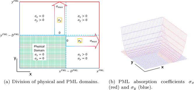
Schematics of physical and PML domains.
Figure 2 shows an example where PML is placed on the top and the right boundaries. The shaded region in Figure 2(a) is the physical domain. The blue dashed lines indicate the interface between physical and PML domains; Figure 2(b) shows the values of σx and σy in the third dimension, colored in red and blue respectively: σx increases from 0 at the vertical dashed line to σmax at the right boundary, and σy increases from 0 at the horizontal dashed line to σmax at the top boundary. The square region on the top right corner is therefore a mix of PML facing downward and leftward, thus both σx and σy are nonzero therein.
3.1. Aeroacoustic Wave Propagation
The first validation case is a planar aeroacoustic wave traveling through a semi-infinitely long straight uniform-cross-section channel. The planar wave is induced with the velocity on the left end prescribed with a Gaussian wave as:
| (14) |
Free-slip boundary condition is applied on the top and bottom boundaries so that the wave remains planar. The result is simply a rightward traveling wave along the straight channel that is eventually absorbed in the PML region placed on the right end. The computational domain is 0.6 cm wide and 5 cm long with a uniform grid of Δx = Δy = 0.04 cm, wherein the PML is placed on the right end with 20 grid layers in thickness, i.e. 0.8 cm in this case. The maximum absorption coefficient is chosen as σmax = 2.4 × 10⁶, using σx defined in Equation (13a), the attenuation factor is then calculated to be 9.3 × 10⁻⁶ based on Equation (5).
Figure 3 shows the velocity profile along the length of the channel at instants t = 0.000 125 s, 0.000 150 s, 0.000 175 s, 0.000 200 s, 0.000 225 s, and 0.000 250 s. Both the numerical solution with PML (solid) and the theoretical solution (dashed) without PML are presented. As the wave travels rightward, it exits the physical domain and enters the PML region (right of the vertical dash-dot line). The theoretical solution shows the traveling wave as if the PML region does not exist. The numerical result reproduces the theoretical solution in the physical domain, while it decays substantially in the PML region as intended. The phase velocity is the acoustic speed c ≈ 33 138 cm/s under the standard conditions given in Section 2. Therefore the peak of the incident wave would theoretically be attenuated to 5.57 × 10⁻⁵ cm/s at the right end of the PML region, on the same order with the peak value of the reflected wave measured to be 9.22 × 10⁻⁵ cm/s in the physical domain.
Figure 3.
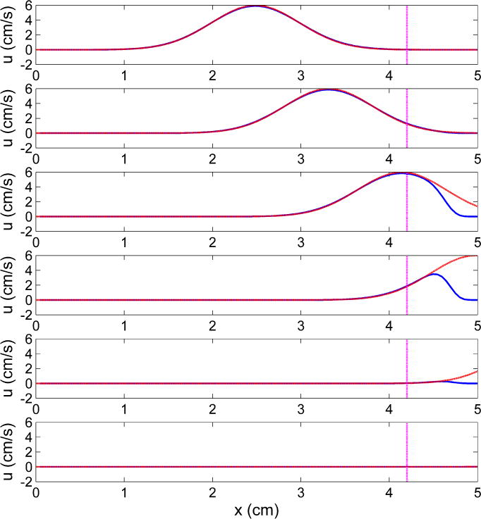
Plane wave propagating along the length of the channel.  (blue solid line): numerical solution;
 (red dash line): theoretical
solution in absence of PML; vertical
  (magenta dash dot line): interface between the physical domain and PML.
Another numerical example is designed to showcase PML absorption of outgoing waves with oblique incidence angles. A planar wave travels rightward in a short section of a straight channel and radiates into an open field connected to the right end of the channel. The resultant radiated wave is roughly cylindrical, therefore has a range of incidence angles to the numerical domain boundaries. The planar wave is induced with a prescribed velocity on the left end of the channel with Equation (14). The computational setup is shown in Figure 4, where the shaded area in Figure 4(a) is where the PML is applied.
Figure 4.
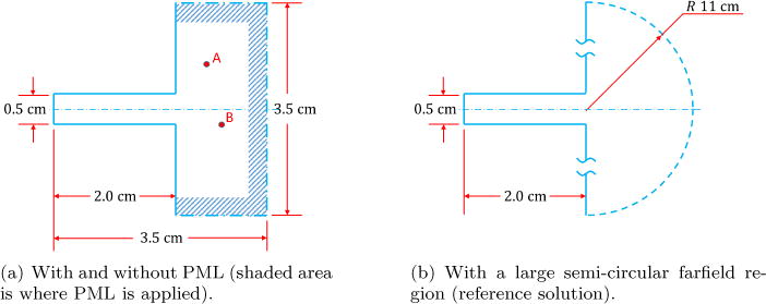
Setup of aeroacoustic wave radiation from a duct to an open field.
A total of 4 cases are examined for comparison. One case is without PML treatment, two of which are with different PML thicknesses, and the fourth case is to physically model the entire open field with a large computational domain. In the case without application of PML, a stress-free boundary condition is applied on the dash-dot-line edges (exit boundaries). Free-slip boundary condition is applied on the other edges, namely the side edges of the straight channel and the left edges of the open field. Two cases are with PML but have different thicknesses, 0.25 cm and 0.50 cm respectively. Finally, for the domain that simulates the open field, an open semi-unbounded farfield with a 11 cm-radius semi-circular region to the right of the channel is modeled. The setup is shown in Figure 4(b). The semi-circular region is designed to have such a large radius so that the radiated wave would not be able to reach its boundary, i.e. its arc, where stress-free boundary condition is applied. With the aeroacoustic wave traveling at 33 138 cm/s, the wave would only have traveled less than 10 cm from the source within the simulation timespan of 3 × 10⁻⁴ s; no spurious reflections would be caused by then.
For the first three cases using the geometry shown in Figure 4(a), the computational domain is discretized with a uniform mesh of Δx = Δy = 0.025 cm. For the far-field geometry, shown in Figure 4(b), the semi-circular region is single-biasedly meshed with element size at about 0.025 cm near the channel opening to 0.6 cm on the arc.
Figure 5 compares the pressure history at two arbitrary locations, points A and B indicated in Figure 4(a), near the exit of the straight duct: point A is 0.5 cm to the right of the channel opening and 0.75 cm above the centerline and point B is 0.75 cm to the right of the channel opening and 0.25 cm below the centerline. The results from the 4 setups are presented and compared: 0.5 cm-thick PML (solid), 0.25 cm-thick PML (dashed), no application of PML (dash-dot), and the reference solution with the semi-circular far-field region (circle markers). It is easily seen that the cases with PML that have either thickness of 0.25 cm or 0.5 cm, the solutions agree very well with the reference solution. In contrast, the solution with no PML nor large far-field region shows significant discrepancies, due to the contaminations of the pressure field caused by the spurious reflections at the exit boundaries.
Figure 5.
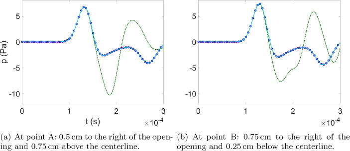
Comparison of pressure time histories at two different locations.  (cyan solid line): with 0.5 cm-thick PML;
 (red dash line): with 0.25
cm-thick PML;
  (green dash dot
line): with no PML;
  (blue circle):
with semi-circular farfield region.
To visually demonstrate the absorption effectiveness of the PML, Figure 6 shows the instantaneous contours of the pressure field at t = 0.000 10 s, 0.000 16 s, and 0.000 30 s. Figure 6(a) are the results with application of 0.50 cm-thick PML on the outflow boundaries, where the lines inside the computational domain are the interface between the physical domain and the PML. Figures 6(b) show the results without the application of PML. At t = 0.000 10 s, the radiated wave just reaches the PML interface in Figure 6(a) while the wavefront has not reached the numerical domain boundary in Figure 6(b), therefore there is no artificial reflection that contaminates the pressure field. At this instance, the pressure contours remain identical in the cases with and without PML. At t = 0.000 16 s and 0.000 30 s, PML continues absorbing waves in Figure 6(a) therefore leaving the pressure contours in the physical domain roughly cylindrical; however artificial reflections from the numerical domain boundaries severely distort the pressure contours without PML, shown in Figure 6(b).
Figure 6.
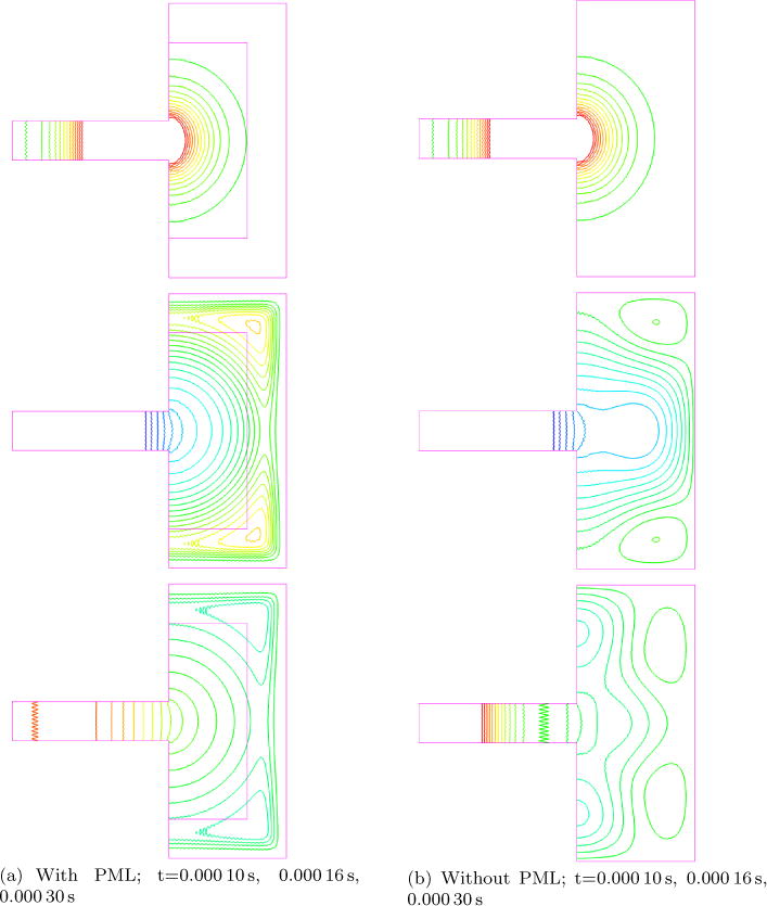
Pressure contours of wave radiation.
3.2. Flow Past a Fixed Cylinder
In this test case, the effectiveness of PML absorbing vortices shed by a viscous flow past a cylinder is studied. This is a typical example of a fluid-structure interaction case where the solid is rigid. The cylinder is 2 cm in diameter placed on the centerline, 7 cm downstream of the inlet on the left, in a uniform-cross-section channel, shown in Figure 7. A uniform incoming velocity of 50 cm/s is applied on the left boundary. A 10 cm-thick PML is placed on the outflow boundary to absorb the outgoing vortices, as shown in Figure 7(a). For comparison, a test case without PML is performed to provide the result with neither non-reflective boundary conditions nor large farfield domain. Finally, to obtain a reference solution, a test case with large farfield region downstream of the cylinder is carried out, making the channel length 55 cm shown in Figure 7(b). Stress-free boundary condition is applied on the outflow boundary in the latter two cases, while free-slip boundary condition is applied on the side edges in all test cases. The rationale behind this test case is that the effects brought about by spurious reflections from the outflow boundary would be more pronounced if the computational boundary is too close to the obstacle. On the contrary, the effects would be negligible if the boundary is placed sufficiently far away at the cost of computational resources due to a much larger computational domain. Application of PML would be able to eliminate the aforesaid effects by absorbing spurious reflections without substantially increasing computational burdens. The computational domains are discretized with quadrilateral elements sized about 0.2 cm.
Figure 7.
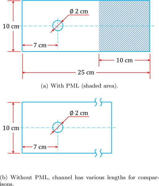
Setup of flow past a cylinder with vortex shedding.
Figure 8 shows the time history plots of the y-velocity and the vorticity strength at 2.5 cm downstream of the cylinder at the centerline. The results from the 3 test cases: with PML, without PML, and with large farfield region (reference solution), are plotted together for comparisons. As clearly shown, with the application of the PML, the results agree very well with the reference solution that has a large downstream farfield region. The slight discrepancies from t = 0.25 s to 0.5 s are caused by the truncation of the initial wake flow at the interface of physical domain and PML before the periodic vortex shedding starts and sustains itself. Similarly observation is found in [22]. In contrast, with no appropriate treatment of outflow boundary, the velocity and vorticity show significant differences from the other two cases, particularly showing altered phases in shedding indicating that there are contaminations of the flow field due to spurious reflections.
Figure 8.
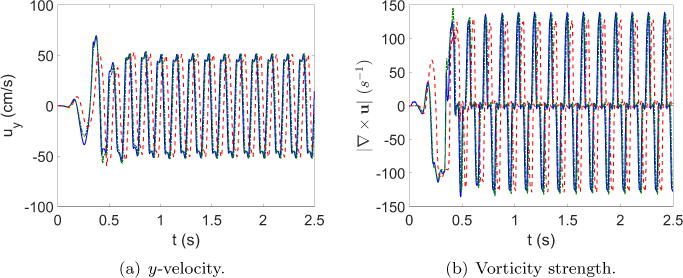
Comparison of time histories of y-velocity and vorticity history
at 2.5 cm downstream of the cylinder along the centerline.  (blue solid line): with PML;
  (green dash dot line): with large farfield
region;
  (red dash line): with no
appropriate treatment of outflow boundary.
Figure 9 shows the comparison of vorticity contours in the 3 aforementioned test cases, at time t = 0.50 s and t = 1.25 s. All figures are focused on the area of interest that is the physical domain from the inflow boundary to 15 cm downstream. The absorption of the vortices in the PML region is clearly observed in Figures 9(a) and 9(b), in which the vorticity contours in the area of interest are comparable to those in Figures 9(c) and 9(d) with large farfield region downstream. In comparison, without appropriate treatment of the outflow boundary, the vorticity contours are shown to have different shapes and the vortex shedding process is out of phase compared to the other two test cases, as shown in Figures 9(e) and 9(f), due to spurious reflections from the outflow boundary located just 7 cm downstream of the cylinder.
Figure 9.
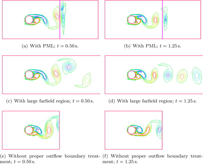
Comparison of vorticity contours in cases with application of PML, shown on the same focused area near the cylinder. (a) and (b): with PML; (c) and (d): with large downstream farfield region; (e) and (f) without proper boundary treatment.
These results show that the PML region efficiently absorbs the flow structures such as the vortices induced from flow past an obstacle and avoids contaminations by spurious reflections, without a significant increase in the computational workload as brought about in the case with the large downstream farfield region.
3.3. Flow Past a Deformable Body with Different Types of Input
In this test study, a 0.2 cm × 0.3 cm rectangular deformable block is placed 0.8 cm from the inflow boundary and attached to the bottom of a 1.0 cm-wide channel, as shown in Figure 10. A 1.0 cm-thick PML is placed at the outflow boundary of a 3.0 cm-long fluid domain as shown in Figure 10(a). For comparison purposes, test cases are also carried out without PML in setups shown in Figure 10(b) with lengths of the channel at 2.0 cm and 8.0 cm. The 8.0 cm case is used as a reference solution that represents an infinitely long channel where the spurious reflection is minimum. The solid has a density of 1.0 g/cm3 that is linear elastic with Young’s modulus of 5000 Pa and a Poisson’s ratio of 0.3. The fluid is air with a density of 1.3 × 10⁻³ g/cm3 and a viscosity of 1.8 × 10⁻⁴ g/(cm · s) that undergoes isentropic process. The solid is relatively stiff compared to the fluid.
Figure 10.
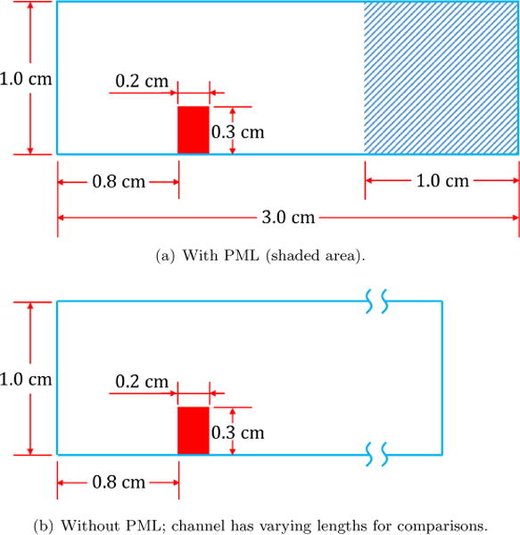
Setup of the fluid-structure interaction test cases.
Two types of boundary conditions are examined. The first inflow boundary velocity is subjected to a sine function oscillating at 1 × 10⁵ Hz between 0 cm/s and 200 cm/s. Free-slip boundary condition is enforced on the top and bottom boundaries, while stress-free boundary condition is applied onto the outflow boundary for the comparison cases of finite length. The solid domain is discretized with uniform grid of quadrilateral elements sized 0.01 cm, and the fluid domain with uniform grid of quadrilateral elements sized 0.02 cm.
Figure 11 shows the time history plot of the displacement at the upper right corner of the solid block in the x-direction, Δx. Initially, all three setups (with PML, with 2 cm and 8 cm channels and no PML) yield the same solution in terms of the solid behavior in response to the inflow. At around 1 × 10⁻⁴ s, the case with no PML starts to deviate from the other two cases, when the spurious reflection from the outflow boundary travels back to the solid block and forcing the solid block to deform differently. Meanwhile, the displacements in the latter two cases agree very well with each other within the simulation timespan, since the spurious reflection has not traveled back to affect the structure deformation in the 8 cm-long channel. The application of PML suppresses spurious reflections altogether.
Figure 11.
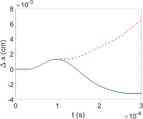
Comparison of x-displacement of the upper right corner of the
solid block in channel with acoustic pulses applied on the inflow boundary.
 (blue solid line): fluid
domain with PML;
  (green dash dot
line): 8 cm × 1 cm fluid domain;
  (red dash line): 2 cm × 1 cm fluid
domain.
A second study case is done by applying a constant pressure of 2.0 Pa onto the inflow boundary with an initially stationary flow field and solid block. Figure 12 shows again the x-displacement of the upper right corner of the solid block. In the case with 2 cm channel and no PML, the spurious reflection from the outflow boundary significantly affects the flow field; in fact, an unphysical vortex travels back from the outflow boundary only 1 cm downstream of the solid block, and collides with the structure and pushes it to the left at around t = 0.04 s, which can be seen in Figure 13(b). In comparison, with the 8 cm channel length, the adverse effects by the spurious reflection is relatively small, since the outflow boundary is farther away from the solid block. However, the x-displacement steadily increases within the simulation timespan, as the pressure at the outflow boundary stays near zero. With the application of PML the x-displacement starts to oscillates around zero and eventually reaches a steady state. This result is expected as in a semi-infinite channel the constant pressure propagates at speed of sound, therefore making the driving force on the structure very small after the initial push. In fact, the vortex downstream of the block is completely absorbed in the PML region, as shown in Figure 13(a), while the flow field near the solid is severely distorted in the case without PML, as shown in Figure 13(b), which in turn affects the solid behavior.
Figure 12.
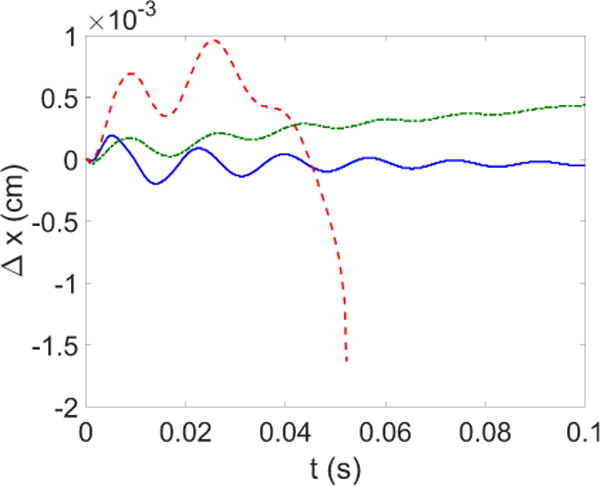
Comparison of x-displacement of the upper right corner of the
solid block in channel with constant pressure applied on the inflow boundary.
 (blue solid line): fluid
domain with PML;
  (green dash dot
line): 8 cm×1 cm fluid domain;
  (red dash line): 2 cm
× 1 cm fluid domain.
Figure 13.
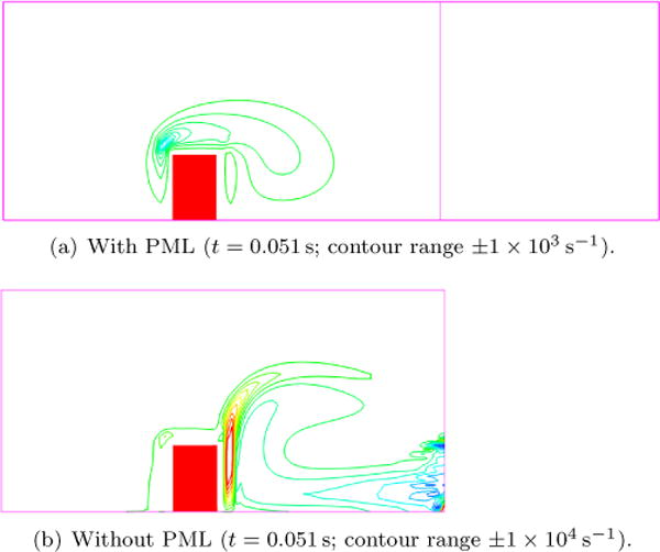
Vorticity contour in the case with application of PML and outflow boundary close to the block.
3.4. Flow Past Deformable Leaflets with Different Heights
In this study, a similar set up is done as in the previous case, however with a softer leaflet that has different heights. A leaflet with a width of 0.2 cm is placed 0.5 cm from the inflow boundary and attached to the bottom of a 1.0 cm×2.0 cm channel. In the case with PML boundary condition imposed, an additional length of 0.5 cm is added. In this study, three different heights of the leaflet, namely 0.4 cm, 0.6 cm and 0.8 cm are applied to compare the difference among the cases with or without PML. The setup is shown in Figure 14. The solid is linear elastic with a density of 1.0 g/cm3, a Young’s modulus of 500 Pa and a Poisson’s ratio of 0.3. The fluid is air with a density of 1.3 × 10⁻³ g/cm3 and a viscosity of 1.8 × 10⁻⁴ g/(cm · s). A constant velocity input of 60 cm/s is applied to the left inflow boundary. Therefore, the Reynolds number for the channel using its width as the characteristic length is Re = 433. The top and bottom are no-slip walls. For the cases without PML, the right boundary has a stress-free outflow condition.
Figure 14.
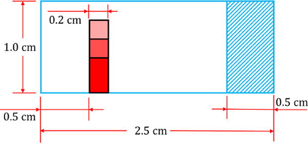
Setup of the flow past deformable leaflets with the height of 0.4 cm, 0.6 cm and 0.8 cm.
The real fluid domain is discretized into 20000 square elements with the side length of 0.01 cm. For the cases with PML, the additional region is composed by a stretching grid for better absorbing efficiency, which has 1200 rectangular elements. The solid domain has 1600, 2400 and 3200 triangular elements for the cases of 0.4 cm, 0.6 cm and 0.8 cm respectively. The time discretization is 1 × 10⁻⁵ s.
Figure 15 shows the comparisons of vorticity contours for the three scenarios with different leaflet heights. The instantaneous contours shown in the figure are chosen right before the cases without PML solutions blowing up. From these contour plots, we can also observe that all the cases without PML show spurious reflection from the outflow boundary, and finally the solutions no longer converge. To the contrary, the PML absorbs the vortices very well. It is evident that in the no-PML cases the spurious reflections come from the breaking up of the vortices that contaminate the real fluid domains. Another closer view of the vortex traveling is shown in Figure 16 (case with 0.4cm height at t = 0.054s). At this instance, the vortex is seen to travel “downward” in the case without PML due to the lacking of absorbing it, while in the PML case the vortex travels horizontally as if the channel is infinitely long.
Figure 15.
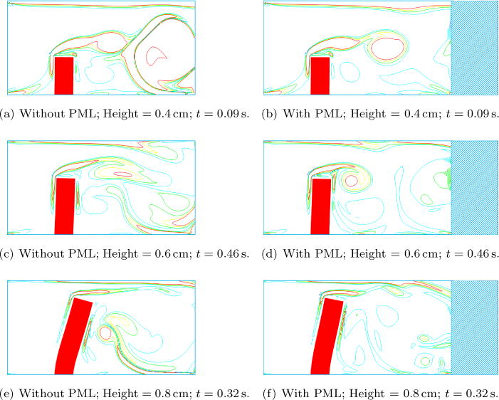
Comparisons of vorticity contours in the three different heights of the leaflet.
Figure 16.

Traveling of vortices.
Finally, to study the impact of PML on the solid deformation, we pick the right top corner on the leaflet and track its displacement. The comparisons between PML and no PML are shown in Figure 17. In the cases of no-PML, the displacement is obviously larger than the PML cases. The discrepancy appears when the first vortex is formed. The spurious reflection increases the magnitude of the velocity in the real fluid domain, which induces unrealistic displacement of the leaflet. The frequency of the case with PML is found to be lower than the case without PML for each height of the leaflet. It can be easily explained that the spurious reflections in the cases of no-PML simply provide a secondary wave that affect the motion of the leaflet. When comparing the different heights, we also notice that intrinsically the shorter leaflet experiences higher natural frequency with a fixed inflow.
Figure 17.
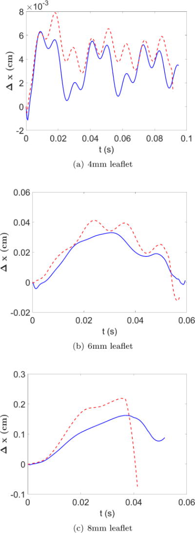
Comparisons for the displacement of the top right node on the leaflet.
 (red dashed line): Cases
without PML;
  (blue solid line):
Cases with PML.
4. Conclusions
In this study, the Perfectly Matched Layer (PML), a non-reflective boundary condition, for finite element method solutions of Navier-Stokes equations in the fluid-structure interaction framework is examined. It is shown to be effective in absorbing outgoing aeroacoustic waves as well as advective flow structures such as vortices in fluids. Furthermore, simulations of fluid-structure interaction in such instances are shown to greatly benefit from the application of PML as well. Proper non-reflective boundary condition avoids contaminations of the flow field from spurious reflection at numerical boundaries, which in turn ensures reasonable and accurate structural response. A series of numerical examples are studied that started with a 1-D planar wave propagation in infinitely long channel, to wave propagations in an open field, to flow past an obstacle involving the advection of vortical structures, and eventually to flow past a deformable solid where the solid deformation can be adversely affected by inaccurate flow waves reflected from numerical boundaries. All the studies demonstrate that appropriate application of PML allows the simulations of aeroacoustic wave propagation and flow advection in unbounded open fields using relatively small numerical domains without the sacrifice of its computational accuracy and efficiency. The numerical framework will be used in the future for simulation of the phonation process, involving fluid-structure interaction between laryngeal airflow and vocal fold structures in a simplified infinitely long channel, such that it is feasible to examine the generated sound directly from the source in this process without the filter effects incurred by a finite-length channel.
Acknowledgments
We would like to acknowledge the partial support from the National Institute of Health (NIH) grant 2R01DC005642-10A1. Author LTZ would like to acknowledge the supports from the National Natural Science Foundation of China (NSFC) grants 11650410650 and 11550110185. Finally, the computational resources at the Center for Computational Innovations at Rensselaer Polytechnic Institute are greatly appreciated.
Footnotes
Publisher's Disclaimer: This is a PDF file of an unedited manuscript that has been accepted for publication. As a service to our customers we are providing this early version of the manuscript. The manuscript will undergo copyediting, typesetting, and review of the resulting proof before it is published in its final citable form. Please note that during the production process errors may be discovered which could affect the content, and all legal disclaimers that apply to the journal pertain.
References
- 1.Colonius T. Modeling artificial boundary conditions for compressible flow. Annual Review of Fluid Mechanics. 2004;36:315–345. [Google Scholar]
- 2.Zhou Y, Wang Z. Absorbing boundary conditions for the Euler and Navier–Stokes equations with the spectral difference method. Journal of Computational Physics. 2010;229(23):8733–8749. [Google Scholar]
- 3.Givoli D. Numerical Methods for Problems in Infinite Domains. Elsevier; 2013. [Google Scholar]
- 4.Heywood JG, Rannacher R, Turek S. Artificial Boundaries and Flux and Pressure Conditions for the Incompressible Navier-Stokes Equations. International Journal for Numerical Methods in Fluids. 1996;22:325–352. [Google Scholar]
- 5.Astley J. Infinite elements for wave problems: a review of current formulations and an assessment of accuracy. International Journal for Numerical Methods in Engineering. 2000;49(7):951–976. [Google Scholar]
- 6.Chen H. Infinite elements for water wave radiation and scattering. International Journal for Numerical Methods in Fluids. 1990;11(5):555–569. [Google Scholar]
- 7.Hughes TJ. Multiscale phenomena: Green’s functions, the Dirichlet-to-Neumann formulation, subgrid scale models, bubbles and the origins of stabilized methods. Computer Methods in Applied Mechanics and Engineering. 1995;127(1):387–401. [Google Scholar]
- 8.Oberai AA, Malhotra M, Pinsky PM. On the implementation of the Dirichlet-to-Neumann radiation condition for iterative solution of the Helmholtz equation. Applied Numerical Mathematics. 1998;27(4):443–464. [Google Scholar]
- 9.Bodony DJ. Analysis of sponge zones for computational fluid mechanics. Journal of Computational Physics. 2006;212(2):681–702. [Google Scholar]
- 10.Bruneau CH. Boundary conditions on artificial frontiers for incompressible and compressible Navier-Stokes equations. ESAIM: Mathematical Modelling and Numerical Analysis. 2000;34(02):303–314. [Google Scholar]
- 11.Colonius T, Ran H. A super-grid-scale model for simulating compressible flow on unbounded domains. Journal of Computational Physics. 2002;182(1):191–212. [Google Scholar]
- 12.Bermúdez A, Hervella-Nieto L, Prieto A, Rodríguez R. Computational Acoustics of Noise Propagation in Fluids-Finite and Boundary Element Methods. Springer; 2008. Perfectly matched layers; pp. 167–196. [Google Scholar]
- 13.Thompson KW. Time dependent boundary conditions for hyperbolic systems. Journal of Computational Physics. 1987;68(1):1–24. [Google Scholar]
- 14.Thompson KW. Time-dependent boundary conditions for hyperbolic systems, II. Journal of Computational Physics. 1990;89(2):439–461. [Google Scholar]
- 15.Poinsot T, Lelef S. Boundary conditions for direct simulations of compressible viscous flows. Journal of Computational Physics. 1992;101(1):104–129. [Google Scholar]
- 16.Albin E, D’Angelo Y. Effects of Navier–Stokes characteristic outflow boundary conditions: modeling for transverse flows. Proceedings of the fifth European Combustion Meeting, Cardiff. 2011 [Google Scholar]
- 17.Martin R, Couder-Castaneda C. An improved unsplit and convolutional perfectly matched layer absorbing technique for the Navier-Stokes equations using cut-off frequency shift. Computer Modeling in Engineering & Sciences(CMES) 2010;63(1):47–77. [Google Scholar]
- 18.Dong S, Karniadakis G, Chryssostomidis C. A robust and accurate outflow boundary condition for incompressible flow simulations on severely-truncated unbounded domains. Journal of Computational Physics. 2014;261:83–105. [Google Scholar]
- 19.Berenger JP. A perfectly matched layer for the absorption of electromagnetic waves. Journal of Computational Physics. 1994;114(2):185–200. [Google Scholar]
- 20.Berenger JP. Perfectly matched layer for the FDTD solution of wave-structure interaction problems. Antennas and Propagation, IEEE Transactions on. 1996;44(1):110–117. [Google Scholar]
- 21.Berenger JP. Three-dimensional perfectly matched layer for the absorption of electromagnetic waves. Journal of Computational Physics. 1996;127(2):363–379. [Google Scholar]
- 22.Hu FQ, Li X, Lin D. Absorbing boundary conditions for nonlinear Euler and Navier–Stokes equations based on the perfectly matched layer technique. Journal of Computational Physics. 2008;227(9):4398–4424. [Google Scholar]
- 23.Sheu YL, Li PC. Simulations of photoacoustic wave propagation using a finite-difference time-domain method with Berenger’s perfectly matched layers. The Journal of the Acoustical Society of America. 2008;124(6):3471–3480. doi: 10.1121/1.3003087. [DOI] [PubMed] [Google Scholar]
- 24.Kalvin V. Limiting absorption principle and perfectly matched layer method for Dirichlet Laplacians in quasi-cylindrical domains. SIAM Journal on Mathematical Analysis. 2012;44(1):355–382. [Google Scholar]
- 25.Kalvin V. Analysis of perfectly matched layer operators for acoustic scattering on manifolds with quasicylindrical ends. Journal de Mathématiques Pures et Appliquées. 2013;100(2):204–219. [Google Scholar]
- 26.Lassas M, Liukkonen J, Somersalo E. Complex Riemannian metric and absorbing boundary conditions. Journal de Mathématiques Pures et Appliquées. 2001;80(7):739–768. [Google Scholar]
- 27.Formaggia L, Gerbeau JF, Nobile F, Quarteroni A. On the coupling of 3D and 1D Navier–Stokes equations for flow problems in compliant vessels. Computer Methods in Applied Mechanics and Engineering. 2001;191(6):561–582. [Google Scholar]
- 28.Formaggia L, Gerbeau JF, Nobile F, Quarteroni A. Numerical treatment of defective boundary conditions for the Navier–Stokes equations. SIAM Journal on Numerical Analysis. 2002;40(1):376–401. [Google Scholar]
- 29.Janela J, Moura A, Sequeira A. Absorbing boundary conditions for a 3D non-Newtonian fluid–structure interaction model for blood flow in arteries. International Journal of Engineering Science. 2010;48(11):1332–1349. [Google Scholar]
- 30.Zhang LT, Gerstenberger A, Wang X, Liu WK. Immersed finite element method. Computer Methods in Applied Mechanics and Engineering. 2004;193(21):2051–2067. [Google Scholar]
- 31.Zhang LT, Gay M. Immersed finite element method for fluid-structure interactions. Journal of Fluids and Structures. 2007;23(6):839–857. doi: 10.1016/j.jfluidstructs.2017.09.002. [DOI] [PMC free article] [PubMed] [Google Scholar]
- 32.Hu FQ, Li X, Lin D. PML absorbing boundary condition for non-linear aeroacoustics problems. American Institute of Aeronautics and Astronautics Journal. 2006;2521:2006. [Google Scholar]
- 33.Hu FQ. On the construction of PML absorbing boundary condition for the non-linear Euler equations. American Institute of Aeronautics and Astronautics Journal. 2006;798:2006. [Google Scholar]
- 34.Pierce AD. Acoustics: an Introduction to its Physical Principles and Applications. McGraw-Hill; New York: p. 1981. [Google Scholar]
- 35.Morse PM. Theoretical Acoustics. Princeton University Press; 1986. [Google Scholar]
- 36.Kinsler LE, Frey AR, Coppens AB, Sanders JV. Fundamentals of Acoustics. Wiley-VCH; 1999. [Google Scholar]
- 37.Hu FQ. A perfectly matched layer absorbing boundary condition for linearized Euler equations with a non-uniform mean flow. Journal of Computational Physics. 2005;208(2):469–492. [Google Scholar]
- 38.Bécache E, Fauqueux S, Joly P. Stability of perfectly matched layers, group velocities and anisotropic waves. Journal of Computational Physics. 2003;188(2):399–433. [Google Scholar]
- 39.Hu FQ. A stable, perfectly matched layer for linearized Euler equations in unsplit physical variables. Journal of Computational Physics. 2001;173(2):455–480. [Google Scholar]
- 40.Wang X, Zhang LT. Interpolation functions in the immersed boundary and finite element methods. Computational Mechanics. 2010;45(4):321–334. [Google Scholar]
- 41.Zhang LT, Wang X, Wang C. Advancements in the Immersed Finite-Element Method and Bio-Medical Applications. Multiscale Simulations and Mechanics of Biological Materials. 2013:207–218. [Google Scholar]
- 42.Wang X, Zhang LT. Modified immersed finite element method for fully-coupled fluid-structure interactions. Computer Methods in Applied Mechanics and Engineering. 2013;267:150–169. doi: 10.1016/j.cma.2013.07.019. [DOI] [PMC free article] [PubMed] [Google Scholar]
- 43.Wang X, Wang C, Zhang LT. Semi-implicit formulation of the immersed finite element method. Computational Mechanics. 2012;49(4):421–430. [Google Scholar]
- 44.Liu WK, Liu Y, Farrell D, Zhang L, Wang XS, Fukui Y, Patankar N, Zhang Y, Bajaj C, Lee J, et al. Immersed finite element method and its applications to biological systems. Computer Methods in Applied Mechanics and Engineering. 2006;195(13):1722–1749. doi: 10.1016/j.cma.2005.05.049. [DOI] [PMC free article] [PubMed] [Google Scholar]
- 45.Gay M, Zhang L, Liu WK. Stent modeling using immersed finite element method. Computer Methods in Applied Mechanics and Engineering. 2006;195(33):4358–4370. doi: 10.1016/j.cma.2005.05.049. [DOI] [PMC free article] [PubMed] [Google Scholar]
- 46.Gay M, Zhang LT. Numerical studies on fluid–structure interactions of stent deployment and stented arteries. Engineering with Computers. 2009;25(1):61–72. [Google Scholar]
- 47.Zhang LT. Modeling of soft tissues interacting with fluid (blood or air) using the immersed finite element method. Journal of Biomedical Science and Engineering. 2014;2014 doi: 10.4236/jbise.2014.73018. [DOI] [PMC free article] [PubMed] [Google Scholar]
- 48.Wang SX, Zhang LT, Liu WK. On computational issues of immersed finite element methods. Journal of Computational Physics. 2009;228(7):2535–2551. [Google Scholar]
- 49.Yang J. PhD Thesis. Rensselaer Polytechnic Institute; 2016. Numerical study of laryngeal airflow dynamics and voiced phonation. [Google Scholar]
- 50.Whitney JP. Master’s Thesis. Massachusetts Institute of Technology; 2006. A Perfectly Matched Layer Method for the Navier-Stokes Equations. [Google Scholar]


