

Abstract
Intra-abdominal pressure may be one of the few modifiable risk factors associated with developing a pelvic floor disorder. With one in eight women having surgery to correct a pelvic floor disorder in their lifetimes, intra-abdominal pressure may be a key to understanding the disease etiology and how to mitigate its occurrence and progression. Many traditional methods of intra-abdominal pressure measurement have limitations in data quality, environment of use, and patient comfort. We have modified a previously reported intravaginal pressure transducer that has been shown to overcome other intra-abdominal pressure measurement technique limitations (Coleman 2012). Our modifications to the intravaginal pressure transducer make it easier to use, less costly, and more reliable than previous designs, while maintaining accuracy, integrity, and quality of data. This device has been used in over 400 participants to date as part of one of the most comprehensive studies examining the relationship between intra-abdominal pressure and pelvic floor disorders.
Keywords: Pressure Transducer, Intra-abdominal Pressure, Vaginal Transducer, Pressure Sensor, Pelvic Floor
1. Introduction
Intra-abdominal pressure (IAP) is a key physiological trait that changes regularly during various activities. Because the peritoneal cavity can be considered a closed space, changes to that volume due to body position, muscle contraction or respiration can change IAP. The changes in IAP may cause a range of physiological and pathophysiological reactions. For example, elevated IAP decreases capillary blood flow in the visceral organs and can lead to significant morbidity and mortality in critical care medicine (Papavramidis, 2011). In the study of biomechanics elevated IAP has been shown to be beneficial in activities such as weightlifting by stiffening the torso and offloading the spine (Stokes, 2010). In urogynecology, elevated IAP is thought to be one of the few modifiable risk factors for women who are at risk for pelvic floor diseases (PFD) such as prolapse and incontinence (Rosenbluth, 2010). One in eight women in the US will have surgery for pelvic organ prolapse in their lifetime and many doctors restrict activities that may elevate IAP, including exercise, in attempts to reduce the risk of primary or recurrent pelvic organ prolapse (Nygaard, 2013). In order to study the association between IAP and PFDs, a pressure transducer was needed that could accurately measure IAP in women during normal activities of daily living.
In 2010, our group reported a generation 1 design of an intravaginal pressure transducer (IVT) to continuously measure IAP in women. The transducer that we developed was accurate, comfortable, less invasive and easy to use (Coleman, 2010). In 2012, we developed a generation 2 wireless IVT device that utilized a miniature wireless telecommunications transmitter that operated in the 402-MHz – 405-MHz MICS band (Medical Implantable Communications Service band, which is a subset of the designated MedRadio frequency band) (Coleman, 2012). This transducer was used extensively to collect IAP data in a series of clinical studies.
Clinical evaluation of the sensor in 2012 validated the second generation IVT as comfortable and easily retained (Hsu, 2012). We then developed standardized methods for reporting IAP measurements (Hamad, 2013) and began using the sensor in physical activity studies (Shaw, 2014), where we found variability amongst individuals performing the same activity. Our sensor allowed for lifting and walking studies outside of the laboratory setting, where we found that activity technique can produce significant changes in IAP (Coleman, 2015a).
For example, women were asked to perform a number of Pilates exercises while their IAP was measured. None of the exercises raised IAP more than lifting 20 pounds or getting out of a chair (Coleman, 2015b). This study provided evidence that women could perform specific exercises, without significant elevations in their IAP. Physicians can use this evidence to help patients resume activities, including exercise, to promote better recovery.
Despite its success and impact, the wireless IVT was not without its drawbacks. The main drawback was the lack of power. The MedRadio standard was intended for fully implantable applications and as such it cannot broadcast radio signals at high RF power; the device we used (Zarlink 70101) has a maximum power of 25 uW. The MedRadio standard was developed in 1999 and was motivated by pacemaker applications (Dortch, 2003). Pacemaker generators have two nice qualities for wireless applications: they are subcutaneous rather than in deep implant sites and they have large surface areas to facilitate antenna placement. Unlike pacemakers, drug delivery pumps and neural stimulators (all devices which use MedRadio wireless) the wireless IVT was in the vagina, a deep implant location, and it did not have the geometry to place a sensitive antenna. Additionally, significant attenuation of the RF signal by abdominal tissues resulted in unreliable data transmission from the IVT. To maximize data quality, we needed overcome these limitations, and so the IVT antenna was externalized and placed in close proximity with the base station. While this generation 2 device was wireless, from a pragmatic view, it was not much different than a wired device.
Based on the experiences with the wireless IVT and other considerations (primarily economic), we elected to make the generation 3 devices wired, which would support a large-scale clinical trial (1300 participants) that investigates the role of IAP and pelvic health in postpartum women (Nygaard, 2017). In this newest design, the IAP data are recorded to a micro SD card, which is then transferred to a computer for data analysis. In this paper we report on the design, development, testing and preliminary clinical use of the device.
2. Materials and Methods
Redesign of the wireless system began by collecting user requirements of the new system. The Motherhood and Pelvic Health (MAP) study is conducted under an approved IRB protocol and informed consent is obtained from all participants. The MAP study is designed to collect IAP data during a set of defined activities at eight weeks and one year postpartum. At each visit, IAP is measured during three activities: abdominal muscle endurance (AME), baby carrier lifting, and Valsalva maneuvers (Nygaard, 2017), which are an attempted exhalation against a closed airway. In order to facilitate data interpretation, participants were asked before each activity to forcefully cough twice and then remain motionless for thirty seconds. After the activity is performed, the participant is asked once again to remain motionless for thirty seconds. The coughing and periods of inactivity are used to assist in interpreting the data record.
When completed, the MAP study will require an estimated 1300 systems to reach clinical endpoints. The limited funding available to the MAP study required financially conscious design decisions. The costs of obtaining participants required a cost-effective, easy to manufacture system that can be produced quickly and perform reliably to avoid data loss from potential malfunction. Study recruitment was expected to go through a ramp-up phase during the first few months and a ramp-down phase once clinical endpoints were near, therefore peak production during the study was estimated to be 15 systems per week. The requirements of the MAP protocol along with the previous wireless system design were used to drive iterative design changes and streamline system production in an academic lab while meeting all the user requirements of the system.
The MAP IAP transducer system retains similar features from the previous designs. The intravaginal transducer (IVT) shape remains unchanged. This shape was shown to be comfortable, easy to insert and remove and was retained in the upper vagina during vigorous activities (Hsu, 2012). The IVT is connected to the instrumentation module (IM) via a flexible cable. The IM provides power, microcontroller, and data storage. A small diameter, flexible silicone tube is part of the IVT and serves to provide reference atmospheric pressure to the silicon pressure transducer.
The most important design change implemented in the new IVT was the implementation of a wired data communication between the IVT and the data recorder/controller. The new design allowed for reduced production costs and more rapid clinical setup of the system. The wired design no longer requires integrated power, processing and a wireless radio in the IVT, resulting in significant simplification of the electronics, which were assembled on a single 1.6cm diameter printed circuit board (PCB). This simplified design also allowed the PCB to be populated in-house using a surface mount technology reflow station, further reducing production costs. For surface mounting, four bare PCBs were placed on a piece of machined aluminum and a laser-cut polyimide stencil was visually aligned over the solder pads. Solder paste (SMD291SNL, Chipquik) was applied over the set of PCBs and electronic components were manually placed on the board for reflow mounting using a rework station (RE-8500 BGA/SMD, Jovy Systems). The populated PCBs from the wireless and wired designs are shown in Figure 1.
Figure 1.
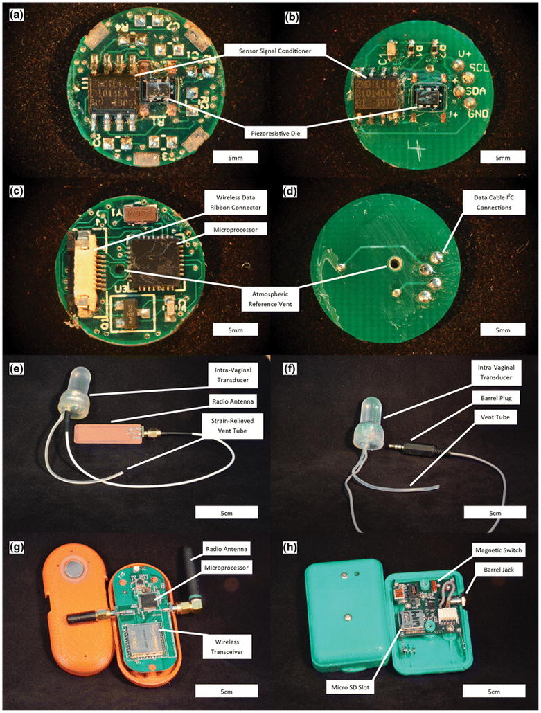
Comparison between the wireless (left images) and wired (right images) Intravaginal Transducer Systems. (a) Sensing side of wireless PCB. (b) Sensing side of wired PCB. (c) Reverse side of wireless PCB. (d) Reverse side of wired PCB. (e) Wireless IVT. (f) Wired IVT. (g) Wireless Base Station. (h) Wired Instrumentation Module.
The IVT was fitted with a five-conductor ultra-flexible cable (NMUF 5/36-2550SJ, Cooner Wire) attached through the bottom end of the device, allowing for I2C communication between the sensor signal conditioner (SSC) (ZSC31014EIG1, Integrated Device Technology) and the data recording IM. A flexible silicone tube (60-011-05, Freudenberg Medical, Dow-Corning Q7-4750 silicone) was fixed to the electronics package by curing small amounts of silicone elastomer on either side of the bottom structural disk while the tether was protruding through.
In order to maintain the geometry and mechanical characteristics of the original device, the structural support of the batteries previously integrated into the IVT was replaced with an aluminum support ring. In an attempt to further reduce production costs, an acrylic support ring was tested in place of the aluminum support ring. During verification testing of the acrylic support ring, the thermal expansion of the plastic caused significant errors in the measured pressure. The support ring was therefore replaced with glass, which showed similar thermal effects to that of the aluminum support rings. The glass ring was glued to the back side of the sensor PCB using UV cure adhesive (3311, Loctite) and the bottom structural disk, described above, was glued to the other side of the glass ring to form a closed electronics package. The electronics package is placed in a molded biocompatible elastomer (MED4940, Nusil) capsule and backfilled with the same material so that neither electronics components nor support components come in contact with the patient. The glass ring is fully encapsulated in high tear strength silicone and does not present an unacceptable risk to the participants.
The wireless base station used in the wireless system was replaced with an IM that housed the system power, microprocessor, and data storage card. The IM and IVT were fitted with a barrel connector jack and plug (171-7435-EX and 161-6435-EX, Kobiconn), respectively. The barrel connections allowed any IVT to be paired with any IM in the clinic quickly and easily. The IM is operated with a magnetic switch, reducing the possibility of accidentally turning off the system during use. The wireless and wired systems are shown in Figure 1.
The original wireless system was gel-filled by first filling the silicone capsule with incompressible silicone gel (MED6350, Nusil) and then pressing the electronics into the capsule. The sensor was subsequently back-filled with silicone elastomer (MED4940, Nusil). This process made it difficult to remove micro bubbles that became trapped on the surface of the gel-contacting portion of the electronics. Any bubbles trapped in the gel caused nonlinear response of the sensor, due to the highly compressible nature of air. The improved gel filling process was developed that reduces the influx of bubbles into the gel-filled capsule. In the new process, a small amount of silicone elastomer is dispensed around the interior neck of the capsule in order to form a seal between the capsule and electronics board. Silicone elastomer is then placed around the electronics-capsule interface on the back of the sensor and cured with a heat gun. Curing the elastomer with a heat gun (HL1800E, Steinel) for 10 seconds at a heat setting of 3 ensures a good seal between the electronics and capsule prior to injection molding the remaining silicone elastomer backfill, which is cured in an oven at 150 °C for 30 minutes.
Once the IVT is back-filled with silicone elastomer, a 1mm incision is made at the top of the capsule dome. Silicone gel is mixed and degassed in a vacuum chamber and then placed into syringes (309661, Becton Dickinson) fitted with precision tips (7018298, Nordson EFD). The syringe is used to inject silicone gel into the capsule, taking care to limit the number of air bubbles introduced. Any visible air bubbles in the silicone gel are “chased out” by slightly overfilling the capsule with gel and using the generated positive pressure to slowly push material back into the syringe. The tip of the syringe is moved around the capsule to capture bubbles, producing a nearly bubble-free capsule. The IVTs are then placed in 75mL centrifuge tubes and spun at 1000 rpm for three minutes. The centrifuge process allows any remaining bubbles to rise to the top of the capsule for subsequent removal through the “chasing” procedure. The gel is then cured in an oven at 70 °C for 30 minutes. After curing the gel, the small incision made at the top of the capsule is filled with silicone elastomer and cured with a heat gun (HL1800E, Steinel) for 10 seconds at a heat setting of 3.
Every IAP transducer system manufactured for clinical use was calibrated to NIST standards in a pressure chamber as previously described (Coleman, 2012). After calibration, each sensor was left for at least 4 hours before verifying the pressure measurements of the system. For verification, the sensor was placed in the pressure chamber and connected to an IM. Pressure data was recorded by the IM while the pressure chamber was stepped through each pressure value used to calibrate the sensor. Data recorded onto an IM was imported to a MATLAB program that determined if the measured pressures were within 2% of the target values. Upon passing verification, the sensor, IM, and SD card numbers, along with the person performing verification, were logged into a table for quality control.
Atmospheric pressure drift has been shown to affect the system (Coleman 2012). When a negative baseline drift occurred in early systems, bridge count values would fall outside the stored calibration range on the SSC. Any values below the calibrated baseline are truncated to zero resulting in loss of data up to the magnitude of the baseline drift. this fault mode is corrected by implementing an SSC offset post-calibration, which would raise the measured baseline pressure to approximately 10–25% of the measurement range and did not affect the sensitivity of the sensor. In clinic, the sensor is turned on and left on a table to collect a baseline before insertion into the participant. The SSC offset can lead to truncation of higher values within the calibration range, but typical IAP pressures measured in vivo do not exceed 200 cm H20, which is 57% of the total range, meaning it is unlikely that any data would be lost due to sensor saturation from implementation of an SSC offset.
Impulse and frequency response tests were conducted on the updated IVT sensor in the pressure vessel previously used for the device (Coleman, 2012). A multifunction pressure waveform generator (WGA-200, Millar Instruments) was connected to an electromagnetic pressure converter (Millar Instruments) mounted atop the airtight compartment. The pressure waveform was controlled by a LabVIEW program and transmitted to the waveform generator through a data acquisition card (PCI-6221, National Instruments). A conventional blood pressure transducer (Deltran DPT-100, Utah Medical) was connected to the pressure chamber through a luer fitting threaded into the side of the pressure chamber. Using the function generator, a swept sine wave and impulse (square wave) tests were performed to analyze the dynamic response of the transducers according to industry guidelines (ANSI/AAMI 1994/(R)2006). Reference pressures were measured at 100Hz through the same LabVIEW program and were converted from voltage to pressures using a calibration transfer function that was created using the NIST traceable pressure transducer used on our calibration system. The MAP IVT measurements were recorded on the IM.
Budget restriction require the MAP sensors to be reprocessed so electronic components within each sensor can be reused (all silicone components are single use only). A reprocessing protocol was developed and approved by the institution’s Environmental Health and Safety Department. Lab personnel complete all reprocessing of materials. The reprocessing procedure begins by donning the appropriate personal protective equipment (face shield, gloves, apron) The IVT is disinfected with a 10% bleach solution and the IM case is cleaned with 70% isopropyl alcohol. Once the IVTs are clean, the silicone elastomer and gel are removed from the electronics with a scalpel. All silicone components are discarded and the electronics are disassembled and cleaned with isopropyl alcohol. A small amount of silicone gel is left covering the area around the piezoresistive die to protect the sensor and fragile wire bonds during subsequent work. Electronics are reused until electrical failure, which is determined after disassembly or during subsequent manufacturing through electrical continuity and component resistance checks. The electronic cable is reused until too short, which was determined to be twenty inches from plug to IVT through consultation with study coordinators.
To meet the budgetary requirements of the study, most of the manufacturing and assembling of the sensor system is done in an academic lab by student volunteers. The production of devices at the rate required by the MAP study is seldom seen in academic setting. This required stringent controls of materials, inventory, and work in progress, along with a robust quality system to ensure all manufactured systems meet performance and user requirements.
3. Results
All changes made to the MAP system were verified against performance specifications and validated against user needs before being implemented into a final design specification and manufacturing process. The barrel connection between the IM and sensor was tested during various mechanical manipulations, such as twisting, wiggling, movement of the wire, and pulling of the wire. Testing results showed that the only failure mode occurred when the plug was slightly removed from the jack creating an electrical short between the power supply and I2C clock conductor lines. This fault was mitigated through enhanced training of study coordinators to ensure the plug was fully connected to the IM before use and periodic checks during data collection. The barrel connection short caused the IM software to enter an error mode that originally required removal of the battery to reset the system. Removal of the battery in a clinical setting was unreasonable, as this required the removal of two tamper-resistant closure screws in the IM case. Therefore, the IM firmware was updated to allow for “hot swapping” of sensors, where the IM microprocessor routinely checked for communication with the sensor SSC and initiated normal measurement once the SSC chip responded to the microcontroller.
The wired sensors showed high linearity during calibration, shown in Figure 2, as previously reported with the wireless sensor. There was not a significant change in thermal offset from room to body temperature of the sensor when the support ring was changed from aluminum (1.84±1.54 cmH20, N=41) to glass (2.02±0.93 cmH20, N=173) (two-tailed t test, p=.34).
Figure 2.
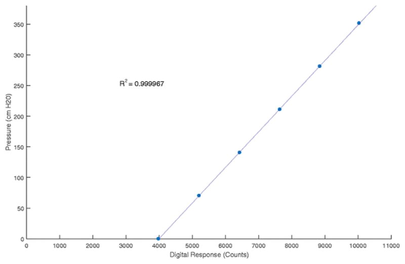
Calibration curve for MAP IVT. The curve shows the response of the sensor is very linear across the pressure range measured by the sensor.
Figure 3 shows the results of a swept sine and impulse tests. The resonance response of the device shows dampening around 26Hz. This dampening is most likely an artifact of the 32Hz sampling rate of the Instrumentation Module and not the IVT itself. The dampening occurs at a frequency much higher than physiologic IAP pressure frequencies, and was determined to be insignificant. The impulse response of the system showed no overshoot or resonance in the wired IVT.
Figure 3.
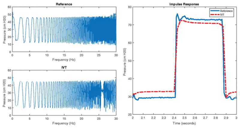
Frequency and Impulse Response of the MAP IVT. The left two graphs show the measured pressure of the MAP IVT and a reference transducer during a swept sine test. The right graph shows the response of the MAP IVT and a reference transducer during a square wave impulse test.
We found that the thermal response of the sensor was the largest source of error in the wired system. The sensor exhibits an inverse response to a step change in ambient temperature. When moved from a room temperature water bath to a body temperature water bath, while ensuring the sensor is placed at the same depth in the water to negate any pressure effects, the measured pressure quickly dips and then slowly climbs to a value higher than the original baseline. The room to body temperature step change is representative of the conditions in the clinical setting, specifically insertion of the sensor into the vagina before performing the set activities.
We collected temperature and pressure data from 141 production sensors that were left in a 20C water bath for 10 minutes before being transferred to a 38C water bath and left to equilibrate. Temperature was measured using a thermistor integrated into the ZSC31014 SSC chip in the IVT. Both temperature and pressure were recorded using a function integrated into the ZSC31014 calibration software. The data were then imported and analyzed using a custom written MATLAB program. The program automatically normalized the data so that pressure before transfer was zero, to account for SSC offset, and the time of transfer between baths was time zero. The transfer time was determined using an algorithm to detect the first drop in pressure associated with temperature change, which from previous experience occurred nearly instantaneously. The transfer between baths was treated as a step change in temperature as the input variable to the system.
MATLAB’s integrated system identification toolbox was used to identify the appropriate transfer function models to fit the sensor data. The process model for temperature response was determined to be an overdamped second-order system without time delay. The pressure response was determined to be an inverse response system without time delay. The data were fit to the time-domain solutions of these systems using a non-linear least squares algorithm and the resulting model with 95% confidence intervals are shown in Table 1. Figure 4 shows the resulting models plotted with sensor data.
Table 1.
Sensor Environmental Temperature Step Change Models and Fitted Results
| Measurement | SSC Temperature | Sensor Measured Pressure | ||
|---|---|---|---|---|
| Frequency-Domain Model |
|
|
||
| Time-Domain Solution |
|
|
||
| Least Squares Results [95% CL] |
K = 17.76 [17.74,17.78] τ1 = 105.6 [105.2, 105.9] τ2 = 21.22 [20.99, 21.46] |
K = 7.43 [7.42, 7.44] τ1 = 91.13 [90.92, 91.33] τ2 = 5056 [5.52, 5.59] τa = −227.17 [−227.39, −226.95] |
Figure 4.

Sensor Response to step in environmental temperature. The top graph shows the temperature of the water bath the sensor is placed in, the transfer between room temperature (20C) and body temperature (38C) baths was treated as an instantaneous step change. The middle graph shows the temperature measured by the ZSC31014 SSC, located near the center of the IVT. The bottom graph shows the pressure measured by the sensor, which exhibits an inverse response with an equilibrium offset. The bottom two graphs show the sensor data (lighter colored lines) and the fitted model (darker solid lines) with 95% CL (darker dashed lines).
The model results show that the thermally induced pressure offset was on average 7.4 cm H20 95% CI [0.7,13.4], an error of 2.1% [0.2%, 3.8%]. The model shows that the inverse response, time to return to zero, of the system only lasts approximately two minutes. The early dynamics of the sensor response to temperature are very quick and are unlikely to significantly affect clinical measurements. From these results we believe the temperature associated errors are reasonable for an in-vivo measurement of IAP, which has high variability in subjects.
Figure 5 shows an example of data collected during a visit with a focus on each of the three performed activities. Abdominal muscle endurance is typically characterized by a rapid increase in IAP, a steady plateau of pressure during the activity, and then a rapid decrease back to resting pressure upon completion. The lifting activity shows greater variability in the pressure tracing between participants. Some participants produce distinct peaks for each of the three performed lifts, while others create tracings where individual lifts cannot be distinguished in the data. The Valsalva maneuver is often most recognizable in the tracing as it is composed of three distinct peaks or plateaus of high pressure, depending on duration of Valsalva.
Figure 5.

MAP visit example data. The top graph shows the overview of data collected during a MAP study visit, including sensor insertion, coughs to indicate activity start, resting periods before and after each activity, and the three activities analyzed for the MAP study. Pressure tracings for each activity is shown below.
Thirty-second resting periods before and after each activity were implemented in the clinical protocol to establish a baseline IAP to compare with the IAP generated during the activity. These resting periods not only helped distinguish activities, with the help of forceful coughs, but also allow for assessment of data quality by comparing the resting IAP before and after each activity. The baseline IAP before and after activities should be similar, as minimal muscle activity should occur in these periods.
4. Discussion
As of May 22, 2017 the MAP study has completed 344 8-week and 66 1-year visits using the wired intra-abdominal pressure sensor. The changes to the IAP system provided an extremely reliable system that successfully collected data for 410 of 429 attempted visits. Several clinical evaluations did not return useful data in early production systems due to atmospheric baseline drift, when no baseline offset was implemented, resulting in large portions of data being truncated to zero pressure. Other systems suffered failures through one of several other modes. Wire bond failures between the piezoresistive die and PCB board caused the measured pressure to saturate. Barrel connection shorts during the IM data write cycle led to corruption of the data stored on the SD card. In some instances, the sensor was not completely plugged in before use or became unplugged during the visit and whole or partial data was lost. All failure modes were identified through thorough root cause failure investigation and replication in the laboratory and appropriate corrective actions to mitigate further failures were implemented by updating manufacturing procedures and clinical protocols.
The current hypothesis for the inverse response caused by external temperature steps is that the difference in thermal expansion coefficients between the silicone elastomer and silicone gel, along with the heat transfer profile within the sensor, causes the observed inverse response. The elastomer is in direct contact with warmer environment and thermally expands before the gel, causing a reduced pressure in the gel. As heat is transferred to the gel, it expands with a higher thermal coefficient of expansion than the elastomer, resulting in an equilibrium baseline pressure reading that is higher than that at lower temperature.
5. Conclusion
The redesigned IAP transducer system successfully met all the user needs of the MAP study. The original wireless data transfer used in the earlier version of the transducer system was replaced with a wired assembly for increased ease of use in the clinic and higher reliability. This required redesign of the sensor electronics package, methods of sensor assembly, firmware and the design of the instrumentation module. An improved method of gel-filling the sensors was introduced, which improved air-bubble-related sensor non-linearity. Reprocessing the sensors to reuse the electronics while replacing components with direct participant contact was described. These changes reduced system cost and facilitated the requirement to produce systems at a quantity much larger than typically seen in academic settings, up to 15 devices every week. All changes were verified through bench testing and validated through communication with study coordinators using formal medical device design control (21 CFR 820.30).
These systems are used to collect data for the Motherhood and Pelvic Health (MAP) study to examine the role of intra-abdominal pressure on pelvic floor disorders. One goal of this study is to provide IAP data to help inform clinicians of risk factors, including IAP, that lead to changes in pelvic floor support and symptoms postpartum. Information derived from the new wired intravaginal transducer may provide insight on modifiable attributes that can reduce the risk of developing a PFD.
Acknowledgments
The authors would like to thank Jens Thomsen for his assistance in firmware development of the wired IVT
Funding: The project described was supported by grant number 1P01HD080629 from the Eunice Kennedy Shriver National Institute of Child Health and Human Development. The content is solely the responsibility of the authors and does not necessarily represent the official views of the Eunice Kennedy Shriver National Institute of Child Health and Human Development or the National Institutes of Health.
Footnotes
Compliance with Ethical Standards
Conflict of Interest: The authors declare that they have no conflict of interest.
Ethical approval: All procedures performed in studies involving human participants were in accordance with the ethical standards of the institutional and/or national research committee and with the 1964 Helsinki declaration and its later amendments or comparable ethical standards.
Informed Consent: Informed consent was obtained from all individual participants included in the study.
Human Subject Research: The research protocol described was approved by the Institutional Review Boards (IRBs) at the University of Utah and Intermountain Healthcare. All participants will complete an informed consent process in either English or Spanish which will be documented in writing.
References
- ANSI/AAMI. (BP22:1994/(R) Blood Pressure Transducers. 2006. [Google Scholar]
- Coleman TJ, Hamad NM, Shaw JM, Egger MJ, Hsu Y, Hitchcock R, Jin H, Choi CK, Nygaard IE. Effects of walking speeds and carrying techniques on intra-abdominal pressure in women. Int Urogynecol J. 2015a;26:967–974. doi: 10.1007/s00192-014-2593-5. [DOI] [PMC free article] [PubMed] [Google Scholar]
- Coleman TJ, Hsu Y, Nygaard IE, Raynes J, Gordon K, Kumathe M, Hitchcock RW. A Gel filled intravaginal transducer for extended measurements of intra-abdominal pressure. 2010 Annual International Conference of the IEEE Engineering in Medicine and Biology. Presented at the 2010 Annual International Conference of the IEEE Engineering in Medicine and Biology; 2010. pp. 1852–1855. [DOI] [PubMed] [Google Scholar]
- Coleman TJ, Nygaard IE, Holder DN, Egger MJ, Hitchcock R. Intra-abdominal pressure during Pilates: unlikely to cause pelvic floor harm. Int Urogynecol J. 2015b;26:1123–1130. doi: 10.1007/s00192-015-2638-4. [DOI] [PMC free article] [PubMed] [Google Scholar]
- Coleman TJ, Thomsen JC, Maass SD, Hsu Y, Nygaard IE, Hitchcock RW. Development of a wireless intra-vaginal transducer for monitoring intra-abdominal pressure in women. Biomed Microdevices. 2012;14:347–355. doi: 10.1007/s10544-011-9611-x. [DOI] [PMC free article] [PubMed] [Google Scholar]
- Dortch MH. 2003 FCC 03-32. [Google Scholar]
- Hamad NM, Shaw JM, Nygaard IE, Coleman TJ, Hsu Y, Egger M, Hitchcock RW. More complicated than it looks: The vagaries of calculating intra-abdominal pressure. J Strength Cond Res. 2013:27. doi: 10.1519/JSC.0b013e31828b8e4c. [DOI] [PMC free article] [PubMed] [Google Scholar]
- Hsu Y, Coleman TJ, Hitchcock RW, Heintz K, Shaw JM, Nygaard IE. Clinical evaluation of a wireless intra-vaginal pressure transducer. Int Urogynecol J. 2012;23:1741–1747. doi: 10.1007/s00192-012-1811-2. [DOI] [PMC free article] [PubMed] [Google Scholar]
- Nygaard IE, Hamad NM, Shaw JM. Activity restrictions after gynecologic surgery: is there evidence? Int Urogynecol J. 2013;24(5):719–724. doi: 10.1007/s00192-012-2026-2. [DOI] [PMC free article] [PubMed] [Google Scholar]
- Nygaard IE, Clark E, Clark L, et al. Physical and cultural determinants of postpartum pelvic floor support and symptoms following vaginal delivery: a protocol for a mixed-methods prospective cohort study. BMJ Open. 2017;7(1):e014252. doi: 10.1136/bmjopen-2016-014252. [DOI] [PMC free article] [PubMed] [Google Scholar]
- Papavramidis TS, Marinis AD, Pliakos I, Kesisoglou I, Papavramidou N. Abdominal compartment syndrome – Intra-abdominal hypertension: Defining, diagnosing, and managing. J Emerg Trauma Shock. 2011;4:279–291. doi: 10.4103/0974-2700.82224. [DOI] [PMC free article] [PubMed] [Google Scholar]
- Rosenbluth EM, Johnson PJ, Hitchcock RW, Nygaard IE. Development and Testing of a Vaginal Pressure Sensor to Measure Intra-abdominal Pressure in Women. Neurourol Urodyn. 2010;29:532–535. doi: 10.1002/nau.20794. [DOI] [PMC free article] [PubMed] [Google Scholar]
- Shaw JM, Hamad NM, Coleman TJ, Egger MJ, Hsu Y, Hitchcock R, Nygaard IE. Intra-abdominal pressures during activity in women using an intra-vaginal pressure transducer. J Sports Sci. 2014;32:1176–1185. doi: 10.1080/02640414.2014.889845. [DOI] [PMC free article] [PubMed] [Google Scholar]
- Stokes IAF, Gardner-Morse MG, Henry SM. Intra-abdominal pressure and abdominal wall muscular function: spinal unloading mechanism. Clin Biomech (Bristol, Avon) 2010;25:859–866. doi: 10.1016/j.clinbiomech.2010.06.018. [DOI] [PMC free article] [PubMed] [Google Scholar]