

Abstract
Accurate segregation of mitotic chromosomes relies in part on a strong linkage between the kinetochores and the plus ends of spindle microtubules (MTs). These attachments are maintained even as the MTs shorten from their kinetochore-associated ends, and despite the large variability in the magnitude of load from the chromosomal “cargo.” Analysis of the underlying mechanisms has recently been facilitated by the identification and purification of various kinetochore complexes. In this chapter we review some existing approaches to study the interaction of these protein complexes with the ends of shortening MTs in vitro. Specifically, we describe the application of a “segmented” MT technique, which allows quantitative characterization of the tracking of the shortening MT ends by fluorescent proteins and protein-coated beads, as well as controlled measurement of the associated forces. There is a marked similarity between these methods and the approaches that are used to study the motions and forces produced by ATP-dependent motor enzymes walking on coverslip-attached, stable MTs. However, optical resolution at the shortening ends of coverslip-tethered MTs is not as good and the thermal noise is high. Furthermore, there are significant differences in the mechanisms of motions of microbeads driven by motors and by MT depolymerization, as well as in the interpretation of the resulting forces. Clearly, the depolymerization-driven motions are difficult to study and the corresponding phenomenology and theories are more complex than in the motors field. We hope, however, that the relatively straightforward assays based on “segmented” MTs, which are described below, will become a routine methodology, thereby helping to advance the studies of the MT-depolymerization-dependent motility.
I. Introduction
Microtubules (MTs) are ubiquitous cytoskeletal polymers that contribute to maintenance of cells shape and intracellular motility and are essential for normal chromosome segregation (Desai and Mitchison, 1997). These functions are carried out with the help of numerous MT-associated proteins and motor enzymes. Traditionally, MT function has been viewed in two parts. First, MTs can serve as stationary tracks for motors and their cargos. Second, growing MTs can themselves help to deliver important cell regulators to cell periphery (Akhmanova and Steinmetz, 2008). The direct role for tubulin depolymerization in transport in reverse direction, toward the minus MT ends, is not so well established. There are at least two processes in which a role for MT depolymerization-dependent “pulling” has been documented. First, shortening MTs can facilitate the motion of large intracellular organelles, such as nuclei in fungi (Molk et al., 2006; Xiang and Fischer, 2004). Since the minus-end-directed MT-dependent motors have also been implicated in this process, the exact contribution of MT shortening per se is not yet clear. Second, shortening MTs can move chromosomes in purified system in vitro (Coue et al., 1991) and in live cells (Grishchuk and McIntosh, 2006; Tanaka et al., 2007). Although the minus-end-directed motor proteins contribute to processivity and fidelity of these motions, their complete deletion does not block anaphase chromosome segregation in both fission and budding yeast, implying that MT depolymerization alone can pull chromosomes.
There are different views about how MT shortening can promote minus-end-directed motility and why the moving cargo does not detach as the MTend shortens. These models will be considered in detail elsewhere (Grishchuk et al., submitted), but briefly, they are based on two physically distinct mechanisms. In the first, motions are driven by the energy accumulated in the lattice of GDP–tubulin polymers, due to a conformational change associated with GTP hydrolysis (Nogales, 2001). This conformational strain causes the plus-end tubulin strands to peel back, a process during which they can produce a power stroke that is strong enough to move microbeads and presumable mitotic chromosomes (Grishchuk et al., 2005; Molodtsov et al., 2005). In this model, MT can exert a measurable force on any attached object, but the continuous, processive motion of a cargo requires a more complex “coupling” adapter. A second model postulates certain energy relationships between attached cargo and the MT lattice; cargo motions are fueled by thermal energy in association with the unidirectionality of tubulin disassembly (e.g., Hill, 1985).
Importantly, in both mechanisms the efficiency of energy transduction by the “depolymerization motor,” the strength of cargo’s attachment, and its ability to move processively crucially depend on the properties of the coupling mechanism: its exact design and energetics of coupler interactions with the MT. For example, a ring-shaped coupler with a given size and MT-connecting linkages can in theory move a cargo with the shortening MT end by either a power-stroke-dependent (“forced walk”) or a power-stroke-independent (“biased diffusion”) mechanism, depending on the binding energies of the system components (Efremov et al., 2007). It follows that in order to determine the mechanism of a coupler’s motion, one should use experimental approaches that can specify quantitative details of the MT–coupler interaction. More practical, and perhaps more interesting, is the question about a given coupler’s performance under various loads, but this problem is much more difficult to address.
The assays that we describe below will help a researcher to explore several properties of a protein complex under study. The possibility that this protein can follow the shortening MT end can be examined by tagging it with a fluorescent label and letting it associate with “segmented” MTs that are free from soluble tubulin and can be induced to depolymerize by the photo-dissolution of a stabilizing cap. A kinetic analysis of this motion and quantification of the brightness of tip-tracking complexes, complemented by measurement of the MT-dependent diffusion (described elsewhere), will help to characterize the energy relationship between this protein and the MT, thereby shedding some light on the possible mechanism of its motion. By conjugating the protein to microbeads and using the same “segmented” MT technique, one can examine whether this protein can carry a light cargo. Further assays using the unevenly labeled beads or “dumbbells” formed from multiple beads will help to address whether these motions are likely to have a biological relevance. Finally, a laser trap can be used on these beads to measure the force with which the MT pulls on them. By comparing beads with strong, static attachments (such as biotin–streptavidin) and by using different bead size, one can deduce the geometry of coupler (ring-shaped or not), reveal the energy efficiency of the coupling, and estimate the maximal forces that this coupler can withstand before detaching.
II. Rationale
MTs are unstable polymers that change their dynamic behavior in response to varying environmental conditions, such as tubulin concentration, buffer composition, and temperature. Several chapters in this book describe assays to study interaction between proteins of interest and MTs in which the dynamic MTs are formed at a low tubulin concentration. Using this technique, one can observe MT growth, but the investigator has to await its spontaneous switch into depolymerization. This method is highly appropriate for high-precision, quantitative analysis of the interactions between a dynamic MT tip and its cargo or a cortex-like barrier. The corresponding experiments, however, are laborious and require a laser trap to manipulate the MT or a bead (Asbury et al., 2006; Hunt and McIntosh, 1998; Kerssemakers et al., 2006). Fluorescent observations are difficult to make in these systems because of high background signal from labeled, soluble tubulin or MT-binding protein. To improve signal/noise ratio, the researcher often has to perfuse these chambers with protein-free buffers. This, however, causes all MTs in the chamber to depolymerize, thereby limiting the number of useful observations.
To circumvent these difficulties, we worked out a system that uses segmented MTs (Grishchuk et al., 2005). MTs are first grown from a suitable, coverslip-attached “nucleator” by using soluble tubulin and GTP. The solution is then changed quickly to introduce a low concentration of fluorescently labeled tubulin and the slowly hydrolysable nucleotide GMPCPP. This exchange adds stable caps to the plus MT ends (Drechsel and Kirschner, 1994), so they will not disassemble when soluble tubulin is removed. The buffer can then be changed, e.g., to vary the concentration of Mg2+ ions (Grishchuk et al., 2005) or to add a fluorescent protein such as Dam1/DASH (Grishchuk et al., 2008b), which can now interact with MTs in the absence of competing soluble tubulin. With a regular mercury arc lamp, the MTs are induced to depolymerize only in the field of view, allowing multiple observations in the same chamber.
Figure 1 provides an outline of the major steps in this technique, described in detail in the following “Materials and Methods” section. Some of these steps (e.g., attachment of the MT “nucleators” to the coverslip) are highly similar, if not identical, to the methods used to study MT-dependent motors and/or plus tip-tracking proteins, so they will be outlined only briefly. Steps that are unique to the segmented-MT approach are described in more detail. The laser-trapping methods, such as instrument calibrations, have been developed and described previously by others, so they will not be covered at all. A detailed description of our experimental equipment can be found in the work of Grishchuk et al. (2008a). The temperature in all our experiments was maintained at 32°C. Unlike most laser-trapping instruments, our optical trap is incorporated into the upright microscope. This feature facilitates work with complex biological samples and beads with high-density protein coats, because large particles, bead aggregates, and contaminants in these samples settle at the bottom of the microscopy chamber and do not interfere with the work at the coverslip atop the chamber. We believe though, that except for this advantage, all techniques described below can be used with inverted microscope without significant modifications.
Fig. 1.

Experimental rationale. (A) Major experimental steps. See Materials and Methods section for details. (B) Schematics of the experimental chamber with a segmented MT (not to scale).
III. Materials and Methods
A. Experimental Perfusion Chambers
The microscopy chambers for experiments with stabilized MTs in vitro are commonly constructed from a glass slide and a No.1 glass coverslip, separated by two parallel strips of a double stick tape. The solutions are added with a pipette on one side of the chamber, and the flow is facilitated by removing liquid with a filter paper on the other side. Such chambers are easy to assemble and use; however, they have two significant disadvantages when working with dynamic MTs. First, the flow of solution is difficult to control and is usually very high, so it tends to break MTs that project into the chamber. Second, if left unsealed, the chambers dry significantly during the course of a 2–3 h experiment at 32°C, thereby changing the concentration of soluble tubulin and other solutes.
We have therefore developed specialized perfusion chambers to use with a high-precision syringe pump. Two thin grooves are made 17–20 mm apart in a regular glass microscopy slide, using an Ultrasonic Mill (Fig. 2). A PE10 tube with inner diameter 0.28 mm (Becton Dickinson, Franklin Lakes, NJ, USA) is glued flush with a glass surface to serve as an entry tube. The exit tube with a larger diameter (0.58 mm) is attached in the second groove. The long sides of the slides are etched to a depth of ~40–60 μm over the areas suitable for positioning two parallel pieces of the double-sided 3 M tape. These indentations reduce the depth of the chamber, so its volume with inlet tubing is only 15–20 μl, thereby economizing the use of proteins and other reagents. A 22 × 22 mm coverslip with sample attached (see below) is then put on top the chamber filled with buffer. Occasional bubbles are removed by applying gentle pressure through the tubes, the edges are sealed with a silicone elastomer (World Precision Instruments, Inc., Sarasota, FL, USA), and the tubes are attached to a PicoPlus pump (Harvard Apparatus, Holliston, MA, USA) with a VC-6 Perfusion Valve Control Systems (Warner Instruments, Hamden, CT, USA). The flow is driven by drawing the liquid out through a larger tube, so the liquid flows in smoothly through the narrower inlet tube, and bubbles do not form. Closed valves seal the chamber completely, removing all drifts and flows, and preventing drying for days. The solutions can be exchanged at a variable and highly reproducible velocity. To reduce the sudden change in pressure upon opening a valve, which often occurs due to inertia of a syringe pump, the built up pressure is released by opening a valve in a tubing pathway that bypasses the perfusion chamber.
Fig. 2.

Perfusion chamber. (A) Schematics, not to scale. (B) Photo of the assembled chamber with connecting tubing on microscope stage. (See Plate no. 55 in the Color Plate Section.)
B. Preparation of Segmented Microtubules Tethered to a Coverslip
Although one can add biological samples to a chamber after it has been assembled, we obtain more reproducible results by attaching MT-nucleating objects to the coverslip prior to its assembly. There are three common ways to nucleate MTs from coverslips that we and others have used. Lysed and deciliated Tetrahymena cells (pellicles) and purified axonemes initiate the growth of MTs with their plus ends away from the coverslip. These two “nucleators” can be purified using published protocols (Lombillo et al., 1993; Myster et al., 1997), and they can be stored frozen in small aliquots for many months. One sample is thawed and added to the center of an ethanol-cleaned coverslip in a Petri dish with a moist paper towel (Lombillo et al., 1993). After 10–120 min incubation, a sizable portion of pellicles and axonemes are stuck to a clean coverslip, but the incubation time and density of these preparations should be worked out empirically to produce a desirable density of the nucleators on the coverslip. The coverslip may then be inverted onto a flow chamber described above; however, if using an inverted microscope, first rinse the coverslip well to remove the abundant unbound material.
Tetrahymena pellicles nucleate dense arrays of MTs, so in some ways they are easier to use; the MT arrays capture protein-coated beads very efficiently, and this is a method of choice if more than one MT attachment per bead is sought. With this nucleator, we have observed that a higher percent of Dam1-coated beads (see below) exhibit MT-dependent motion, and they travel more processively than when using axonemes, where MT arrays are not nearly as dense. However, pellicles are 20–40 μm in size, so the observations are usually made deep in a chamber, where most MT plus ends are located, but where optical resolution is not optimal. Furthermore, the pellicles are quite compliant, i.e., they deform under force, so one must exercise caution when using them for high-precision force measurements. Chlamydomonas axonemes, on the other hand, provide a more rigid attachment to the coverslip, and they nucleate only two to four well separated MTs at oblique angles with a coverslip, so they are suited better for differential interference contrast (DIC) visualization and force measurements.
A third frequently used nucleator is prepared from GMPCPP-stabilized MT seeds (Howard and Hyman, 1993). Since one such seed nucleates only one MT, this is a method of choice if one seeks to observe a single MT or a single MT–bead contact. The disadvantages of this nucleator are as follows: (1) it leaves some ambiguity about MT polarity unless the NEM–tubulin seeds that grow only from the plus end are used (Hyman et al., 1991), (2) GMPCPP MTs usually have ≥14 protofilaments, while the intracellular MTs have 13 (Hyman et al., 1995; Tilney et al., 1973), and (3) these MTs grow very close to the coverslip, so the behavior of the MT tip-tracking complexes and MT end-associated beads may be affected by the surface proximity. There are several published protocols that can be used to attach these seeds to the coverslip: via the antitubulin antibodies (e.g., Helenius et al., 2006) or rigor kinesin (e.g., Powers et al., 2009) or by growing the seeds from a mixture of biotinylated and unmodified tubulin, with their subsequent attachment to the streptavidin-coated coverslip (e.g., Berliner et al., 1994).
Once the desired MT nucleator has been attached to the coverslip, the chamber has been assembled and placed on the microscope stage at 32°C (this temperature can be maintained with an objective heater from Bioptechs, Butler, PA, USA); segmented MTs can be prepared with the following procedure:
Thaw on ice one aliquot of unlabeled tubulin (10 μl, 10 mg/ml), Rhodamine-labeled tubulin (5 μl, 5–10 mg/ml), GMPCPP (7 μl, 10 mM purchased from Jena Bioscience GmbH, Jena, Germany), Mg–GTP (10 μl, 50 mM), dithiothreitol (DTT) (100 μl, 100 mM), and casein (200 μl, 10 mg/ml). If using streptavidin-coated beads, also thaw biotinylated tubulin (5 μl, 5–10 mg/ml). The unlabeled and modified tubulins can be purchased from Cytoskeleton, Inc., Denver, CO, USA or prepared by using published protocols (e.g., Hyman et al., 1991; Lombillo et al., 1993; http://mitchison.med.harvard.edu/protocols/).
Prepare and keep on ice 5 ml motility buffer: 80 mM K–PIPES, pH 6.9, 4 mM MgCl2, 1 mM EGTA, 1–2 mM DTT, and 0.5 mg/ml casein.
Prewarm 400 μl motility buffer to 32°C and perfuse at 100 μl/min to wash all unbound material from the chamber.
Prewarm to 32°C for 30 s 45 μl of a solution containing approximately 1.5 mg/ml unlabeled tubulin and 1 mM GTP. Tubulin concentration should be chosen based on the quality of tubulin preparation and the desired rate of MT elongation. Perfuse at 30 μl/min. Follow MT growth with DIC optics.
When MTs reach the desired length (usually 10–15 μm in 10–20 min) prewarm at 32°C for 30 s 65 μl of a mixture of unlabeled and Rhodamine-labeled tubulin and 0.5 mM GMPCPP. Final concentrations and the ratio of these tubulins are determined empirically for each tubulin preparation and the degree of Rhodamine labeling. For 5 mg/ml preparation of Rhodamine tubulin with degree of labeling 1 (one molecule of dye per tubulin dimer), we routinely mix 59 μl motility buffer and 3.5 μl GMPCPP with 1.5 μl of each unlabeled and labeled tubulins. Perfuse at 20 μl/min.
Incubate for about 10 min, then perfuse warm motility buffer at 10 μl/min for 5–10 min. This wash removes the abundant GMPCPP MT seeds that nucleate spontaneously in a warm chamber. Excessive washing, however, will also remove some pellicles or axonemes. The Rhodamine-labeled MT caps should be 2–4 μm long; they will disintegrate in minutes upon illumination by a mercury arc lamp filtered through Rhodamine or Texas Red filter cubes, depending on the brightness of the excitation light and the degree of Rhodamine labeling in the caps.
These segmented MTs remain stable for hours at 32°C, so long as there is a minimal number of subsequent perfusions. We have determined that similar results can be obtained with fluorescein isothiocyanate (FITC)-labeled tubulin, but not with Alexa750. The latter caps bleach without disintegration, and MTs remain stable. The ability of fluorescently labeled MT to disintegrate upon illumination appears to result from a photodamage caused by free radicals (Vigers et al., 1988). Consistently, inclusion of oxygen scavengers, such as glucose oxidase and catalase enzymatic system, abolishes the depolymerization of MTs when their Rhodamine-containing caps are photobleached.
C. Assays to Study Tip-Tracking of the Depolymerizing Microtubules
Although several MT-associated proteins can track the growing MT end (Akhmanova and Steinmetz, 2008), only one protein complex has so far been demonstrated to move processively in a bead-free context with the end of an MT that shortens under physiological conditions: the Dam1/DASH from budding yeast. Originally, Stefan Westermann and his colleagues at the University of Berkley, CA, used a mixture of Alexa488-labeled Dam1 complex and Rhodaminated tubulin with GTP to observe Dam1 tracking of the MTs, which were induced to depolymerize by dilution (Westermann et al., 2006). MTs in this experimental assay were not anchored in a chamber, so a thickening agent, methylcellulose, was added to minimize MTs’ thermal motions. A drop in tubulin concentration promoted catastrophic disassembly of all MTs, so the samples had to be scanned quickly to identify a suitably positioned MT before all the polymers had shortened. Application of the segmented MT technique, however, allows much greater control over the experimental conditions. Many observations can be made with a single experimental chamber because only the MTs in the illuminated area are induced to depolymerize. Furthermore, the thickening agents, which are known to induce clumping of proteins, including Dam1, can be omitted.
Recombinant Dam1 complex is relatively straightforward to purify; it readily labels with Alexa dyes, binds well at nanomolar concentrations to MTs, and tracks MT ends spectacularly well (Westermann et al., 2005). The above-described motility buffer may be used for Dam1 with two important modifications. Adding bovine serum albumin (BSA) at 4–8 mg/ml improves the imaging quality, because it greatly reduces a nonspecific Dam1 sticking to glass surface. Second, the presence of potent reducing agents, such as ≥5 mM DTT or 0.5–1% β-mercaptoethanol (βME), is essential for observing Dam1 tracking, although Dam1-coated beads exhibit some motility even without these agents (Grishchuk et al., 2008b). After perfusing Dam1 in motility buffer supplemented with βME and BSA, scan the chamber to identify a segmented MT decorated with green Alexa488-Dam1 dots, illuminate the field briefly through Texas Red filter cube until the red cap begins to crumble, and then switch back into the FITC or GFP channel to observe tracking. To record these motions acquire four to six planes in a stack with 0.3 μm step every 2–4 s, and either with a suitable software or manually identify planes in which the MT end is in focus. The resulting stack of best-focus images can be analyzed by building kymographs or by measuring the intensity of tip-tacking complexes with image-processing software, such as MetaMorph (Molecular Devices, Downingtown, PA, USA).
To quantify the number of protein molecules that travel with the shortening MT end, it is necessary first to measure the intensity of the signal that corresponds to a single fluorophore. This is customarily achieved by adding a highly diluted concentration of fluorescently labeled protein to a regular flow chamber with two parallel strips of a double stick tape, washing well the unbound protein, and recording the changes in intensity of coverslip-attached fluorescent dots as they bleach. For accurate determination of the intensity signal associated with the bleaching of a single fluorophore, the recordings from each dot are first smoothed and the intensity of the background is subtracted. The resulting data can then be analyzed with two algorithms: Gaussian fitting of the fluorescence intensity histogram (Park et al., 2005) and the algorithm based on pairwise distance difference (Block and Svoboda, 1995). Using these algorithms one can test the “null” hypothesis that the collected data represent a gradual exponential photobleaching free of any steps (see SI Text in Grishchuk et al., 2008b). If this hypothesis is ruled out, these algorithms are then used to calculate the magnitude of the single bleaching step that would provide the best fit to the experimental photobleaching curves. A consistent answer from both methods testifies to the accuracy with which the size of the bleaching step has been determined.
We have previously used the above approaches in combination with photobleaching to demonstrate that the Dam1 tip-tracking complexes contain enough subunit to form one full MT-encircling structure; however, several rings do not travel together (Grishchuk et al., 2008b). When a tracking ring runs into a smaller, lattice-attached Dam1 complex, this stationary complex may be collected and will move together with the first, ring-size complex. However, if a Dam1 complex large enough to form a ring is encountered, it causes the MT depolymerization to pause until the Dam1 subunits more proximal to MT tip dissociate and the remaining complex becomes small enough for MT depolymerization to resume. We interpreted these results to suggest that a Dam1 ring forms strong bonds with the MT wall. Consequently, a sliding motion of the single ring requires the full extent of the power strokes of bending MT protofilaments, and the “depolymerization motor” is not strong enough to plow several Dam1 rings. Consistent with the proposed “forced walk” mechanism of ring’s sliding (Efremov et al., 2007), the ring-size complexes slow down the rate of MT depolymerization, indicating an energy transduction process. At lower concentrations of soluble Dam1 or with a mutant Dam1-S4D protein, which forms rings less frequently (Wang et al., 2007), one can observe the tip-tracking by only a few Dam1 subunits, and, as one would expect, they no longer impede MT depolymerization (Grishchuk et al., 2008a). Strong adhesion between the ring coupler and MT wall is proposed to ensure the stable attachment of a cargo to a shortening MT end, which is essential for accurate chromosome segregation.
D. Tracking Shortening Microtubule Ends by Protein-Coated Beads
Ongoing cellular research to uncover the mechanisms that ensure stable chromosomal attachment to shortening MT ends has, in the last decade, received a boost, thanks to the identification and purification of many kinetochore-associated complexes (reviewed in Welburn and Cheeseman, 2008; Westermann et al., 2007). Unfortunately, the in vitro assays to analyze the functional roles of these complexes have lagged behind. Conjugation of the proteins of interest to microbeads with the subsequent examination of their MT-depolymerization-dependent motility remains one of the most informative in vitro approaches (Lombillo et al., 1993). This methodology has demonstrated that numerous protein complexes can support some MT-depolymerization-dependent bead motility, including Dam1/DASH, Ndc80, Ska1-complexes, and kinesin-like proteins (Asbury et al., 2006; Grishchuk et al., 2008b; Grissom et al., 2009; Lombillo et al., 1995; McIntosh et al., 2008; Powers et al., 2009; Welburn et al., 2009; Westermann et al., 2006). However, the recent work with Dam1-coated beads has revealed that beads can move with the shortening MT ends via different mechanisms: one that depends on bead rotation and one that does not. The former is obviously a poor model for chromosome motility, so proteins that display such a property are not necessarily involved in kinetochore coupling in vivo. Clearly, much remains to be learned about the biophysical properties of the proteins that can support these different types of motions. In this section, we describe ways to conjugate proteins to microbeads so as to study their MT-dependent motility. The following Section E describes some additional tests that can be used to determine whether bead rolling plays a role in these motions.
There are several strategies to conjugate proteins to the surface of polystyrene or glass spheres. The choice between them is usually dictated by the presence of a particular tag on the protein complex under study. A polyhistidine tag is small and enables an efficient, one-step, affinity purification of the expressed protein, so it is a tag of choice for many kinetochore proteins. The 6His-fusion protein can then be conjugated to the beads via antibodies that recognize this tag. This strategy is particularly valuable because more direct conjugation of the proteins to bead’s surface frequently produces less active beads. Indeed, the commercial polystyrene beads with covalently attached streptavidin have very little affinity for biotinylated MTs, as compared to the same beads additionally coated with biotinylated BSA and then another streptavidin layer (our unpublished result). These additional layers of coatings appear to provide a better environment for bead–MT interactions, presumably by presenting proteins in a more favorable conformation and by providing more sites for attachment to the cylindrical MT wall.
Commercial polystyrene beads with dense streptavidin coating can be purchased from Bangs Laboratories Fishers, IN, USA or other vendors. These beads remain active for many months; however, they do not freeze well, so antibody and protein conjugation has to be carried out for each experimental use. Furthermore, polystyrene microbeads have less stability along the optical axis of a laser beam, so thermal motions of the MTs, unless they are very short, can promote sudden “sinking” of a 0.5-μm bead when the MT begins to shorten. Glass beads of the same size are easier to trap, and they can be fully prepared and frozen in aliquots for longer use, if the protein of interest is amenable to freezing.
We had little luck, however, with glass streptavidin-coated beads purchased from Bangs Laboratories; higher streptavidin density was obtain by using the COOH-activated beads from the same company. To coat these beads with streptavidin, perform the following steps:
Weigh 5 mg of 0.52-μm beads (catalog # SC02N) and mix with 0.5 ml of MES buffer (25 mM MES, pH 5, 0.05% Tween 20, filtered through 0.2-μm pores and stored frozen in aliquots). Disperse beads until they are single by repeated rounds of pipetting through a narrow plastic tip, vortexing (5 s at a time), and sonication (in ice-cold bath, 5 min at a time).
Spin in microcentrifuge 4–6 min at 3,000 g and resuspend in 100 μl MES buffer.
Pre-weigh SulfoNHS (Sigma-Aldrich, St. Louis, MO, USA, catalog #56485) and EDC (Thermo Fisher Scientific, Inc. Rockford, IL, USA, catalog # 22980) to dissolve each in 100 μl of MES buffer (final concentration 50 mg/ml), and immediately add these solutions to beads, followed by vortexing. Incubate for 30 min at room temperature on a rocker, vortexing every 5 min.
Spin and wash three times in 1 ml of MES buffer.
Resuspend in 200 μl MES buffer with 50 μg streptavidin. Incubate with mixing at 4°C overnight.
Spin, resuspend in 40 mM glycine, and incubate for 20 min at room temperature to quench the reaction.
Wash three times and resuspend in 0.5 ml MES buffer. Beads can be stored at 4°C with mixing for at least 2 months without losing their activity, as judged by staining with FITC–biotin. The resulting density of streptavidin coating is about 10-fold less than of the commercial streptavidin-coated plastic beads (Bangs Laboratories, catalog # CP01N), but it is significantly more dense and stable than the coating on the glass beads purchased from the same source.
These or commercial polystyrene streptavidin-coated beads can then be incubated with biotinylated antibodies that recognize polyhistidine tag. Wash to remove unbound antibodies and incubate with a tagged protein in a suitable buffer [e.g., PIPES or phosphate-buffered saline (PBS)]. Dam1 complex tagged with 6His will bind to the beads in less than 1 h incubation at 4°C. A common problem with this procedure is that most proteins cause beads clumping. The clumping can be partially prevented by using more diluted bead and protein suspensions, adding BSA, casein, or low level of detergents, and brief vortexing and sonication. Prolonged vortexing and sonication should be avoided to prevent damaging the bead-associated protein layers.
Perfuse a bead suspension into a chamber with segmented MTs, and wait for 5–10 min to allow bead binding to the MTs. When selecting a bead for analysis, first observe its motion on an anchored MT. A microbead attached to a single MT should diffuse in a smooth arc, without any change in radial distance (along MT axis). When working with 0.5–1 μm beads, it is often possible to see the attached MT with DIC optics; however, larger beads sink and bend their associated MT, so it becomes harder to visualize. With experience, one can become proficient at selecting a “good” bead (i.e., attached to a single MT). More elaborate tests of the attachment can be done with a laser trap, e.g., by pulling slightly on the attached bead: a “good” bead should move freely over 1–3 μm distances in the direction perpendicular to MT axis, move slightly toward the MT’s attachment site, and resist any pulls along MT axis away from the seed. If the bead passes these tests, record its thermal motions with low light DIC via Texas Red filter cube for 5–20 s, and then open the fluorescence shutter to illuminate the field of view and briefly close the incandescent light shutter to improve visualization of the red cap. If a single bead–MT interaction is sought, but more than one red end is seen associated with the bead, discontinue and move on to the next bead. If a single red end is found where expected, based on the bead’s arc-like motion and/or DIC imaging, open the incandescent light shutter and continue recording until the bead arrives at the MT minus end and/or detaches.
This technique works well with proteins that have a high affinity for the GDP part of the segmented MTs; one can collect tens of recordings from a single experimental chamber. However, some kinetochore proteins stick better to the GMPCPP-containing lattice, so beads are frequently found at the red caps (Rhodamine itself also appears to promote some nonspecific bead attachment). If a bead is attached to the middle or a distal tip of the red cap, it will almost always detach from the MT after the cap is illuminated. However, beads, which are found close to a junction between the Rhodamine-containing and unlabeled tubulin segments, have a good chance of “catching” the shortening GDP end. The efficiency of tracking is also improved if the bead is attached to several MTs, and we see processive motions more frequently when Dam1-coated beads are tested with pellicles, which nucleate dense MT arrays.
E. Analysis of the Mechanism of Bead Motions
Original experiments demonstrating that MT depolymerization alone can support the motion of protein-coated beads in vitro were carried out with MT-dependent motors in the absence of ATP (Lombillo et al., 1995). These authors found that dynein and several kinesins can couple motion of the beads to shortening bundles of MTs grown from Tetrahymena pellicles. A chimeric Drosophila kinesin NK350, which combined a motor domain of kinesin heavy chain with a stalk of NCD (Stewart et al., 1993), lacked a traditional ATP-dependent motility but was particularly successful in coupling beads to MT depolymerization. Strikingly, the NK350-coated beads moved significantly faster than the normal rate of MT depolymerization, so they appeared to induce MT disassembly. When attached to the coverslip in a traditional MT-gliding assay, NK350 chimera supported diffusive motions of stable MTs (Lombillo et al., 1995). This correlative link between a protein’s diffusive behavior and its ability to support bead coupling has promoted two hypotheses to explain beads motions. It has been suggested that NK350 carry the bead toward the minus MT end by stepping in this direction under the pushing force of bending protofilaments (Lombillo et al., 1995). Peskin and colleagues, on the other hand, built a mathematical model, in which the beads moved with the shortening MT ends via a rotational diffusion (Peskin and Oster, 1995; Tao and Peskin, 1998).
This dispute has not yet been settled, and even seemed to have been forgotten, e.g., when the Dam1 complex was first purified and tested in analogous assays. First, Stefan Westermann with colleagues (Westermann et al., 2006) and then Charles Asbury’s lab (Asbury et al., 2006) have reported the MT-depolymerization-dependent motions of the microbeads coated with Dam1 complexes. Since structural data had provided compelling evidence that Dam1 can oligomerize into the ring structures around stabilized MTs in vitro, it was assumed that the Dam1-coated beads were carried by the MT ends with the help of the MT-encircling rings. Some indirect arguments were proposed to support this idea (for discussion, see Grishchuk et al., 2008b), and further work with these beads has also been interpreted in this vein (Franck et al., 2007).
Application of the segmented MT assays, however, has allowed us to examine this interpretation by a quantitative analysis of the statistically large number of Dam1-coated beads under well-controlled experimental conditions. We have shown that in the presence of soluble Dam1 the Dam1-coated beads move at the rates similar to those seen for Dam1 complexes without the beads, suggesting that soluble Dam1 promoted formation of ring structures for beads coupling (Grishchuk et al., 2008b). However, in the absence of soluble Dam1 the moving beads accelerated the rate of MT depolymerization and moved much faster than the Dam1 complexes alone. The similarity between the latter type of motion and the NK350-coated beads, which were almost certainly not coupled by ring-like structures, prompted a direct test of the idea that such fast motions could result from bead rolling. To carry out such a test, we have prepared the beads with an uneven coating of the fluorescent Dam1 by using the following protocol:
Take 1.5 μl of a 1% suspension of 1 μm polystyrene streptavidin-coated beads. Wash them once at 4°C in PBS–BSA buffer (PBS supplemented with 2 mg/ml BSA and 2 mM DTT) by spinning 15 min at 3,000 g and resuspending in 60 μl of PBS–BSA.
Take one “centrifugal device” (Pall Corporation, Port Washington, NY, USA, Nanosep MF 0.2 μm). With a sharp razor blade, cut out the green plastic bottom part of the filter device, so that the filter membrane can be accessed from the bottom. Pre-wet the membrane by adding 20 μl of PBS–BSA on top of the membrane, then add the beads. Spin 2 min at 325 g at 4°C.
Add 2 μl of biotinylated anti-His5 antibodies (Qiagen Inc., Valencia CA, USA) to 58 μl PBS–BSA. Resuspend beads by pipetting and incubate with gentle vortexing/shaking for 1 h.
Add 0.1 mM biotin to block all remaining streptavidin-binding sites, spin immediately, and wash twice with 400 μl of PBS–BSA by spinning as above. After the last wash, blot all remaining liquid with a filter paper, so that the membrane is moist but not wet.
Add 0.5–2 μl of Alexa488-Dam1 complexes with His6 tag (0.1 mg/ml) directly to the bottom side of the filter and incubate for 5–10 min. When all conditions are right, the monolayer of the beads on the inner side of the filter will be exposed to fluorescently-labeled Dam1 diffusing through the filter, so the beads will become coated unevenly by this protein. Wash twice as above.
Add 20 μl of Dam1 with His6 tag but no fluorescent label (0.1 mg/ml) to the top of the membrane. Mix well with beads by pipetting and incubate with gentle vortexing for 1 h at 4°C. All remaining sites for binding the polyhistidine tag to beads’ surface will now become saturated with non-fluorescent complexes, eventually providing even coating by Dam1 protein but with asymmetric fluorescent mark. Wash twice (if using with soluble Dam1 or at least four times if no soluble Dam1 will be added to a chamber) with 400 μl of PBS–BSA.
Resuspend in 100 μl motility buffer (80 mM K-PIPES, ph 6.9, 1 mM EGTA with 4 mM MgCl2, 2 mM DTT, 0.5 mg/ml casein, 5 mg/ml BSA, and 1% βME) with or without soluble Dam1 and perfuse in a chamber with segmented MTs.
Record bead motions upon induction of MT depolymerization with GFP (or FITC) filter cube using stream acquisition (300 ms exposure).
This experimental approach is quite challenging in part because 1-μm beads used here to improve spatial resolution of the fluorescent mark move less frequently than the smaller 0.5-μm beads. Furthermore, the distal MT ends jiggle due to thermal noise; the beads bind to these MTs in random orientations, so the fluorescent marks are sometimes obscure and the plane of bead rotation may change in time. These features make it difficult to obtain many recordings of beads motions in which the presence or absence of rolling is obvious. We have therefore developed the following procedure to analyze all recorded motions, thereby speeding up this approach.
Use image analysis software to collect coordinates for the positions of a fluorescent “mark” on the bead’s surface as it moves (this can be a brightest speckle or a middle of the fluorescent crescent). For each frame also collect the coordinates of the bead’s center.
Record the coordinates that define MT orientation (if the DIC image of MT is not available, use the linear approximation of the trajectory for the bead’s motion).
Calculate the projection of the vector that connects the center of the bead and the “mark” onto the MT axis by using MatLab program.
Plot these data versus time and calculate the corresponding SD.
Compare the resulting values with those obtained under controlled conditions, e.g., for beads attached statically to a coverslip or to tethered but not depolymerizing MTs. The larger SD indicates higher rotational mobility (Fig. 3).
Fig. 3.
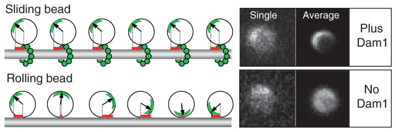
Dam1-coated beads can move via two different mechanisms depending on the availability of soluble Dam1. Left panel illustrates that when bead slides, a projection on the MT axis of the vector from bead’s center to the fluorescent mark (red bars) does not change, while in the rolling bead this measure changes significantly. Right panels show images of two 1-μm Alexa488-Dam1-coated beads that tracked the shortening MT ends in our assay. Both beads had a fluorescent mark, as seen on their “single” images (one frame from the corresponding sequences). The bead on top moved without rolling (soluble Dam1 was present), so when all images in this sequence were centered and averaged, a fluorescent crescent became highly visible. Lower “average” image is for the bead that tracked shortening MT end in a buffer with no
Using these procedures, we were able to confirm that in the presence of soluble Dam1 the rotational mobility of the Dam1-coated beads was as low as for nonmoving control beads (Grishchuk et al., 2008b). This is consistent with a translational type of motion, which is expected if the bead is coupled to the shortening MT via a ring-like structure. However, in the absence of soluble Dam1, the Dam1-coated beads had significantly higher rotational mobility, and on several of the recordings, the beads were observed to roll. This unusual phenomenon deserves further analysis, so that we may learn about the specific properties of the protein couplers, such as Dam1 and perhaps NK350, which enable such motility. However, the finding that efficient and processive bead motion can occur by the rolling mechanism is also alarming, because this type of motion is probably fundamentally different from the coupling mechanisms used by mitotic chromosomes.
It is important to continue development of the assays that would facilitate distinguishing between these mechanisms of beads’ motility for other protein couplers. In addition to Dam1, a similar analysis has been carried out only with one other protein—the fission yeast heterodimeric kinesin-like protein Klp5/6 (Grissom et al., 2009). This work used a much easier approach, in which the absence of the rotation was deduced from visualizing small clamps of beads, which can be found occasionally in any bead preparation. By observing aggregates of two to three beads, coated with Klp5/6 in the absence of ATP, we have determined that these beads move with shortening MT ends by a rotation-independent mechanism. It is not yet clear how Klp5/6 promotes such motility, but the additional observation that bead “dumbbells” move more frequently than the single beads may indicate that a protein-coated crevice provides a more suitable geometry for coupler–MT interaction than the spherical surface. This approach, however, cannot replace the more challenging method with the fluorescently marked beads, because bead aggregates may have a bias toward a non-rolling motion.
Two kinetochore complexes, both containing Ska1 protein from human cells, can also promote MT depolymerization motion of the microbeads (Welburn et al., 2009). The corresponding mechanisms have not yet been determined, although the observed difference in the kinetics of beads motions (full Ska1 complex moves detectably slower than the smaller, two-subunit complex) indicates that they may be distinct. The impediment of MT depolymerization by the full Ska1 complexes suggests that its oligomers provide some cross-bridging of the adjacent MT protofilaments, similarly to the Dam1-containing rings. Finally, there have been two reports about the coupling properties of the kinetochore Ndc80 complex from different organisms (McIntosh et al., 2008; Powers et al., 2009). Despite the diversity of proposed mechanisms, it has not yet been shown that the Ndc80-coated beads can move without rolling.
F. Measurement of the Forces Developed by Depolymerizing Microtubules
The segmented MT methodology is particularly useful when measuring the force developed by depolymerizing MT. Since MT depolymerization can be triggered at will by the user, this approach provides great flexibility with choosing the buffer composition, selecting a bead–MT pair, and examining bead attachment beforehand. Initial visual examination of the attached bead is carried out as described above. If the trap is stationary, move the stage until the bead’s image is centered with a position of the beam, then open the laser shutter to trap the bead. For a trap stiffness of about 0.01 pN/nm, the trapped bead should show roughly two-fold smaller thermal fluctuations in the direction parallel to MT. Move the stage or tweezers with a trapped bead in 0.05 μm steps both parallel and perpendicular to the MT axis. A properly attached bead will become displaced from the trap’s center only with movements parallel to the MT. If the bead passes these tests, slightly pull to displace the bead from the trap’s center (Fig. 4). Induce MT depolymerization and continue recording until the bead detaches. This event is easy to spot because the unbound bead quickly relocates to the trap’s center. If no initial tension was applied, bead’s detachment can be detected either by an increase in smoothness of the recording or via a lack of response to changes in laser position. Run calibrations, and search the field to identify another attached bead. The resulting signals can be analyzed by fitting with curves that describe exponential decay or a decay preceded by a rising part (see Supplemental information in Grishchuk et al., 2005).
Fig. 4.

Measurement of MT depolymerization force. Quadrant photo-detector signals for two representative beads (diameter 0.5 micrometer) show that force measured with biotin-streptavidin coupling is much smaller than with Dam1, consistent with an idea that soluble Dam1 forms an MT-encircling ring, which couples the bead to the MT. (See Plate no. 57 in the Color Plate Section.)
We have previously used this approach to study the beads which were attached to MT wall by strong, static linkages (Grishchuk et al., 2005). If streptavidin-coated beads are added to a chamber that contains polymerizing, biotinylated tubulin, the streptavidin becomes quickly saturated with soluble tubulin and these beads fail to bind to the MTs. However, capping the MTs with subsequent removal of biotinylated nonpolymerized tubulin allowed us to target these beads to the biotinylated GDP-containing segments of the MTs. Similarly, beads coated with MT-binding proteins enriched for Tau and MAP2 can also attach statically to the walls of segmented MTs. Unlike Dam1 and other protein couplers described above, these and streptavidin-coated beads do not show processive motions and detach from the MT when it depolymerizes. However, when the position of such a bead is recoded with nm resolution, one can see that the bead moves slightly toward the MT minus end just prior to the bead’s detachment. Based on stiffness of our trap, we estimated that an average displacement of a 1-μm bead corresponded to 0.2 pN force applied at the bead’s center. However, such force should comprise only a small fraction of the force with which bending MT protofilaments pushed on beads’ surface, because of the relatively large bead size and its lateral attachment to the MT. This supposition was tested directly by Grishchuk et al. (2008a) by using beads with different sizes, and indeed the detected force was inversely proportional to the bead’s diameter. Thus, unlike the motor-dependent bead motions, in which the measured stalling force corresponds directly to the maximum load the motor can carry, the interpretation of measured MT-dependent depolymerization force requires careful evaluation of the bead–MT configuration. Consideration of the “lever-arm” effect for statically attached beads leads to a fairly large estimate of the maximum depolymerization force (up to 60 pN per MT; Grishchuk et al., 2005).
The same technique can be used to measure depolymerization-dependent forces with beads coated with different coupling proteins. For example, when beads are attached to the MTs under conditions that promote the formation of Dam1 rings, significantly larger forces are observed (Grishchuk et al., 2008a) (Fig. 4). This difference is explained by a notion that the force developed at the end of the shortening MT is roughly a sum of forces generated by its 13 protofilaments. A bead attached via the MT-encircling ring should therefore collect about six-fold larger force than a bead attached laterally to the MT wall, presumably via two adjacent protofilaments. Thus, the “segmented” MT technique is very useful for comparing different coupling attachments and mechanisms.
IV. Summary and Discussion
This chapter describes a “segmented” MT technique, which allows quantitative characterization of the tracking of the shortening MT ends by fluorescent proteins and protein-coated beads, as well as controlled measurement of the associated forces. A perfusion chamber with good flow- and thermo-regulation provides a well-controlled environment for solid experimental work, so it is well worth the investment. With such a chamber the capped segmented MTs can be easily obtained to give both experimental flexibility and the possibility of many experiments per one chamber, conserving proteins and time. Application of these methods for close analysis of the motility associated with MT depolymerization reveals unexpected complexity in the phenomenology: bead cargo can roll or slide, some couplings slow down the rate of MT depolymerization while the others induce disassembly, and forces developed by the shortening MTs depend on the coupling mechanism and size of the bead. As more proteins that can track the shortening MT ends are discovered, the methods described here will hopefully help to identify the mechanisms of their motions, as well as to address their significance in enabling chromosomal motions.
Acknowledgments
We are grateful to our colleagues Maxim Molodtsov, Vladimir Volkov, Nikita Gudimchuk, Ilia Spiridonov, Paula Grissom, and J. Richard McIntosh, who contributed to the development of these protocols; and to J. Richard McIntosh for reading the manuscript. Purified Clamydomonas axonemes for our experiments were kindly provided by Mary Porter, University of Minnesota. This work was supported in part by National Institutes of Health grant GM033787 to JRM and RFBR grants 07-04-91134 and 09-04-12077 to FIA.
References
- Akhmanova A, Steinmetz MO. Tracking the ends: A dynamic protein network controls the fate of microtubule tips. Nat Rev Mol Cell Biol. 2008;9:309–322. doi: 10.1038/nrm2369. [DOI] [PubMed] [Google Scholar]
- Asbury CL, Gestaut DR, Powers AF, Franck AD, Davis TN. The Dam1 kinetochore complex harnesses microtubule dynamics to produce force and movement. Proc Natl Acad Sci U SA. 2006;103:9873–9878. doi: 10.1073/pnas.0602249103. [DOI] [PMC free article] [PubMed] [Google Scholar]
- Berliner E, Mahtani HK, Karki S, Chu LF, Cronan JE, Jr, Gelles J. Microtubule movement by a biotinated kinesin bound to streptavidin-coated surface. J Biol Chem. 1994;269:8610–8615. [PubMed] [Google Scholar]
- Block SM, Svoboda K. Analysis of high resolution recordings of motor movement. Biophys J. 1995;68:230S–239S. [PMC free article] [PubMed] [Google Scholar]
- Coue M, Lombillo VA, McIntosh JR. Microtubule depolymerization promotes particle and chromosome movement in vitro. J Cell Biol. 1991;112:1165–1175. doi: 10.1083/jcb.112.6.1165. [DOI] [PMC free article] [PubMed] [Google Scholar]
- Desai A, Mitchison TJ. Microtubule polymerization dynamics. Annu Rev Cell Dev Biol. 1997;13:83–117. doi: 10.1146/annurev.cellbio.13.1.83. [DOI] [PubMed] [Google Scholar]
- Drechsel DN, Kirschner MW. The minimum GTP cap required to stabilize microtubules. Curr Biol. 1994;4:1053–1061. doi: 10.1016/s0960-9822(00)00243-8. [DOI] [PubMed] [Google Scholar]
- Efremov A, Grishchuk EL, McIntosh JR, Ataullakhanov FI. In search of an optimal ring to couple microtubule depolymerization to processive chromosome motions. Proc Natl Acad Sci U SA. 2007;104:19017–19022. doi: 10.1073/pnas.0709524104. [DOI] [PMC free article] [PubMed] [Google Scholar]
- Franck AD, Powers AF, Gestaut DR, Gonen T, Davis TN, Asbury CL. Tension applied through the Dam1 complex promotes microtubule elongation providing a direct mechanism for length control in mitosis. Nat Cell Biol. 2007;9:832–837. doi: 10.1038/ncb1609. [DOI] [PMC free article] [PubMed] [Google Scholar]
- Grishchuk EL, Efremov AK, Volkov VA, Spiridonov IS, Gudimchuk N, Westermann S, Drubin D, Barnes G, McIntosh JR, Ataullakhanov FI. The Dam1 ring binds microtubules strongly enough to be a processive as well as energy-efficient coupler for chromosome motion. Proc Natl Acad Sci U SA. 2008a;105:15423–15428. doi: 10.1073/pnas.0807859105. [DOI] [PMC free article] [PubMed] [Google Scholar]
- Grishchuk EL, McIntosh JR. Microtubule depolymerization can drive poleward chromosome motion in fission yeast. EMBO J. 2006;25:4888–4896. doi: 10.1038/sj.emboj.7601353. [DOI] [PMC free article] [PubMed] [Google Scholar]
- Grishchuk EL, McIntosh JR, Molodtsov MI, Ataullakhanov FI. Force generation by dynamic microtubule polymers. Manuscript submitted for publication. [Google Scholar]
- Grishchuk EL, Molodtsov MI, Ataullakhanov FI, McIntosh JR. Force production by disassembling microtubules. Nature. 2005;438:384–388. doi: 10.1038/nature04132. [DOI] [PubMed] [Google Scholar]
- Grishchuk EL, Spiridonov IS, Volkov VA, Efremov A, Westermann S, Drubin D, Barnes G, Ataullakhanov FI, McIntosh JR. Different assemblies of the DAM1 complex follow shortening microtubules by distinct mechanisms. Proc Natl Acad Sci U SA. 2008b;105:6918–6923. doi: 10.1073/pnas.0801811105. [DOI] [PMC free article] [PubMed] [Google Scholar]
- Grissom PM, Fiedler T, Grishchuk EL, Nicastro D, West RR, McIntosh JR. Kinesi -8 from fission yeast: A heterodimeric, plus-end-directed motor that can couple microtubule depolymerization to cargo movement. Mol Biol Cell. 2009;20:963–972. doi: 10.1091/mbc.E08-09-0979. [DOI] [PMC free article] [PubMed] [Google Scholar]
- Helenius J, Brouhard G, Kalaidzidis Y, Diez S, Howard J. The depolymerizing kinesin MCAK uses lattice diffusion to rapidly target microtubule ends. Nature. 2006;441:115–119. doi: 10.1038/nature04736. [DOI] [PubMed] [Google Scholar]
- Hill TL. Theoretical problems related to the attachment of microtubules to kinetochores. Proc Natl Acad Sci U SA. 1985;82:4404–4408. doi: 10.1073/pnas.82.13.4404. [DOI] [PMC free article] [PubMed] [Google Scholar]
- Howard J, Hyman AA. Preparation of marked microtubules for the assay of the polarity of microtubule-based motors by fluorescence microscopy. Methods Cell Biol. 1993;39:105–113. doi: 10.1016/s0091-679x(08)60164-8. [DOI] [PubMed] [Google Scholar]
- Hunt AJ, McIntosh JR. The dynamic behavior of individual microtubules associated with chromosomes in vitro. Mol Biol Cell. 1998;9:2857–2871. doi: 10.1091/mbc.9.10.2857. [DOI] [PMC free article] [PubMed] [Google Scholar]
- Hyman AA, Chretien D, Arnal I, Wade RH. Structural changes accompanying GTP hydrolysis in microtubules: Information from a slowly hydrolyzable analogue guanylyl-(alpha,beta)-methylene-diphosphonate. J Cell Biol. 1995;128:117–125. doi: 10.1083/jcb.128.1.117. [DOI] [PMC free article] [PubMed] [Google Scholar]
- Hyman A, Drechsel D, Kellogg D, Salser S, Sawin K, Steffen P, Wordeman L, Mitchison T. Preparation of modified tubulins. Meth Enzymol. 1991;196:478–485. doi: 10.1016/0076-6879(91)96041-o. [DOI] [PubMed] [Google Scholar]
- Kerssemakers JW, Munteanu EL, Laan L, Noetzel TL, Janson ME, Dogterom M. Assembly dynamics of microtubules at molecular resolution. Nature. 2006;442:709–712. doi: 10.1038/nature04928. [DOI] [PubMed] [Google Scholar]
- Lombillo VA, Coue M, McIntosh JR. In vitro motility assays using microtubules tethered to Tetrahymena pellicles. Methods Cell Biol. 1993;39:149–165. doi: 10.1016/s0091-679x(08)60168-5. Ref Type: Serial (Book Monograph) [DOI] [PubMed] [Google Scholar]
- Lombillo VA, Stewart RJ, McIntosh JR. Minus-end-directed motion of kinesin-coated microspheres driven by microtubule depolymerization. Nature. 1995;373:161–164. doi: 10.1038/373161a0. [DOI] [PubMed] [Google Scholar]
- McIntosh JR, Grishchuk EL, Morphew MK, Efremov AK, Zhudenkov K, Volkov VA, Cheeseman IM, Desai A, Mastronarde DN, Ataullakhanov FI. Fibrils connect microtubule tips with kinetochores: A mechanism to couple tubulin dynamics to chromosome motion. Cell. 2008;135:322–333. doi: 10.1016/j.cell.2008.08.038. [DOI] [PMC free article] [PubMed] [Google Scholar]
- Molk JN, Salmon ED, Bloom K. Nuclear congression is driven by cytoplasmic microtubule plus end interactions in S. cerevisiae. J Cell Biol. 2006;172:27–39. doi: 10.1083/jcb.200510032. [DOI] [PMC free article] [PubMed] [Google Scholar]
- Molodtsov MI, Grishchuk EL, Efremov AK, McIntosh JR, Ataullakhanov FI. Force production by depolymerizing microtubules: A theoretical study. Proc Natl Acad Sci U SA. 2005;102:4353–4358. doi: 10.1073/pnas.0501142102. [DOI] [PMC free article] [PubMed] [Google Scholar]
- Myster SH, Knott JA, O’Toole E, Porter ME. The Chlamydomonas Dhc1 gene encodes a dynein heavy chain subunit required for assembly of the I1 inner arm complex. Mol Biol Cell. 1997;8:607–620. doi: 10.1091/mbc.8.4.607. [DOI] [PMC free article] [PubMed] [Google Scholar]
- Nogales E. Structural insight into microtubule function. Annu Rev Biophys Biomol Struct. 2001;30:397–420. doi: 10.1146/annurev.biophys.30.1.397. [DOI] [PubMed] [Google Scholar]
- Park M, Kim HH, Kim D, Song NW. Counting the number of fluorophores labeled in biomolecules by observing the fluorescence-intensity transient of a single molecule. Bull Chem Soc Jpn. 2005;78:1612–1618. [Google Scholar]
- Peskin CS, Oster GF. Force production by depolymerizing microtubules: Load-velocity curves and run-pause statistics. Biophys J. 1995;69:2268–2276. doi: 10.1016/S0006-3495(95)80097-4. [DOI] [PMC free article] [PubMed] [Google Scholar]
- Powers AF, Franck AD, Gestaut DR, Cooper J, Gracyzk B, Wei RR, Wordeman L, Davis TN, Asbury CL. The Ndc80 kinetochore complex forms load-bearing attachments to dynamic microtubule tips via biased diffusion. Cell. 2009;136:865–875. doi: 10.1016/j.cell.2008.12.045. [DOI] [PMC free article] [PubMed] [Google Scholar]
- Stewart RJ, Thaler JP, Goldstein LS. Direction of microtubule movement is an intrinsic property of the motor domains of kinesin heavy chain and Drosophila ncd protein. Proc Natl Acad Sci U SA. 1993;90:5209–5213. doi: 10.1073/pnas.90.11.5209. [DOI] [PMC free article] [PubMed] [Google Scholar]
- Tanaka K, Kitamura E, Kitamura Y, Tanaka TU. Molecular mechanisms of microtubule-dependent kinetochore transport toward spindle poles. J Cell Biol. 2007;178:269–281. doi: 10.1083/jcb.200702141. [DOI] [PMC free article] [PubMed] [Google Scholar]
- Tao YC, Peskin CS. Simulating the role of microtubules in depolymerization-driven transport: A Monte Carlo approach. Biophys J. 1998;75:1529–1540. doi: 10.1016/S0006-3495(98)74072-X. [DOI] [PMC free article] [PubMed] [Google Scholar]
- Tilney LG, Bryan J, Bush DJ, Fujiwara K, Mooseker MS, Murphy DB, Snyder DH. Microtubules: Evidence for 13 protofilaments. J Cell Biol. 1973;59:267–275. doi: 10.1083/jcb.59.2.267. [DOI] [PMC free article] [PubMed] [Google Scholar]
- Vigers GP, Coue M, McIntosh JR. Fluorescent microtubules break up under illumination. J Cell Biol. 1988;107:1011–1024. doi: 10.1083/jcb.107.3.1011. [DOI] [PMC free article] [PubMed] [Google Scholar]
- Wang HW, Ramey VH, Westermann S, Leschziner AE, Welburn JP, Nakajima Y, Drubin DG, Barnes G, Nogales E. Architecture of the Dam1 kinetochore ring complex and implications for microtubule-driven assembly and force-coupling mechanisms. Nat Struct Mol Biol. 2007;14:721–726. doi: 10.1038/nsmb1274. [DOI] [PubMed] [Google Scholar]
- Welburn JP, Cheeseman IM. Toward a molecular structure of the eukaryotic kinetochore. Dev Cell. 2008;15:645–655. doi: 10.1016/j.devcel.2008.10.011. [DOI] [PubMed] [Google Scholar]
- Welburn JP, Grishchuk EL, Backer CB, Wilson-Kubalek EM, Yates JR, III, Cheeseman IM. The human kinetochore Ska1 complex facilitates microtubule depolymerization-coupled motility. Dev Cell. 2009;16:374–385. doi: 10.1016/j.devcel.2009.01.011. [DOI] [PMC free article] [PubMed] [Google Scholar]
- Westermann S, Avila-Sakar A, Wang HW, Niederstrasser H, Wong J, Drubin DG, Nogales E, Barnes G. Formation of a dynamic kinetochore–microtubule interface through assembly of the Dam1 ring complex. Mol Cell. 2005;17:277–290. doi: 10.1016/j.molcel.2004.12.019. [DOI] [PubMed] [Google Scholar]
- Westermann S, Drubin DG, Barnes G. Structures and functions of yeast kinetochore complexes. Annu Rev Biochem. 2007;76:563–591. doi: 10.1146/annurev.biochem.76.052705.160607. [DOI] [PubMed] [Google Scholar]
- Westermann S, Wang HW, Avila-Sakar A, Drubin DG, Nogales E, Barnes G. The Dam1 kinetochore ring complex moves processively on depolymerizing microtubule ends. Nature. 2006;440:565–569. doi: 10.1038/nature04409. [DOI] [PubMed] [Google Scholar]
- Xiang X, Fischer R. Nuclear migration and positioning in filamentous fungi. Fungal Genet Biol. 2004;41:411–419. doi: 10.1016/j.fgb.2003.11.010. [DOI] [PubMed] [Google Scholar]