

Abstract
This study describes a non-dilutive high-gradient magnetic separation (HGMS) device intended to continuously remove malaria-infected red blood cells (iRBCs) from the circulation. A mesoscale prototype device with disposable photo-etched ferromagnetic grid and reusable permanent magnet was designed with a computationally-optimized magnetic force. The prototype device was evaluated in-vitro using a non-pathogenic analog for malaria-infected blood, comprised of 24% healthy RBCs, 6% human methemoglobin RBCs (metRBCs), and 70% phosphate buffer solution (PBS). The device provided a 27.0 ± 2.2% reduction of metRBCs in a single pass at a flow rate of 77 μL min−1. This represents a clearance rate over 380 times greater throughput than microfluidic devices reported previously. These positive results encourage development of a clinical scale system that would economize time and donor blood for treating severe malaria.
Keywords: magnetics, microfluidic, malaria, apheresis, separation, treatment, modeling
INTRODUCTION
Malaria, caused by the protozoan parasite Plasmodium falciparum, infected over 200 million people and caused an estimated 438,000 deaths in 201540. In the most severe cases, blood exchange therapies are implemented to rapidly reduce the parasite load. However, this is a very inefficient process because the infused blood mixes with infected circulating blood as it is not possible to “drain and refill” the patient. Consequently, it requires a great deal of donor blood which, in under-resourced settings, is a scarce commodity, and greatly increases the risk of transfusion reactions and transfection of other blood-borne diseases. This dilemma motivates the development of a filtration device that can selectively remove the infected cells from the circulation. Such a device should take advantage of unique properties of malaria-infected RBCs (iRBCs), one of which being their increased magnetic susceptibility. During the life cycle of the P. falciparum, it feeds off the host RBC’s hemoglobin and oxidizes the low spin iron into a high spin form. The resultant hemozoin crystal imparts a paramagnetic property to the iRBC30. Early-stage ring iRBCs have a net volumetric magnetic susceptibility relative to water, Δχ in SI units, of 0.82×10⁻⁶. The later-stage trophozoite and schizont susceptibility is 0.91×10⁻⁶ and 1.8×10⁻⁶, respectively16. In contrast, healthy RBCs are diamagnetic, and exhibit negative value of susceptibility (Δχ = −0.18×10⁻⁶). Deoxygenated RBCs (deoxyRBCs) are however paramagnetic (Δχ = 3.3×10⁻⁶) as is methemoglobin RBCs (metRBCs) (Δχ = 3.8×10⁻⁶)10,31.
Magnetic-based separation has been used for azz wide variety of medical and industrial applications, including cancer cell detection25, apheresis22, and including as municipal water purification23. The process can be greatly enhanced by chemically binding magnetic particles or beads to target cells or pathogens like circulating cancer cells (CTCs), E. coli, or fungi8,14,36. An alternative method for capturing weakly paramagnetic cells that cannot be readily conjugated is high-gradient magnetic separation (HGMS). The most common HGMS separators combine a strong permanent magnet with ferromagnetic wires, steel wool packed columns, magnetic bead-packed MACs columns (Miltenyi Biotec Inc., San Diego, CA, USA), or micro-patterned shapes as described by several investigators1,2,9,13,20,21,24,26,29,32,38. The capture efficiency of these devices has been reported as great as 90%, however they must be used in batch mode, typically requiring a dwell phase to allow the cells to be captured, followed by a rinse phase to flush these cells out of the capture medium. These devices are therefore not practical for treating a patient in continuous dialysis-like fashion. They would also be likely to result in hemodilution and/or loss of healthy cells. An additional challenge for separating malaria infected cells is that the early stage iRBC, which includes “ring stage” and “early trophozoite” stages, occurs within the first 30 hours of the 48 hour lifecycle, and represents the majority of circulating iRBCs; are less paramagnetic than the targets typically captured by these devices. Several research groups have introduced microfluidic HGMS devices to concentrate paraRBCs such as deoxyRBCs or metRBCs12,22,28,31. However, these previous devices require the initial blood samples to be highly diluted. HGMS devices, which implement a parallel saline sheath layer, further dilute the exiting sample due to diffusive flow.
This study investigated the performance of a novel mesoscale continuous HGMS device intended for selectively removing malaria-infected RBCs from whole blood, without the need for dilution or a sheath flow (Fig. 1). The device is comprised a parallel-plate flow passage with manifolds at both ends. Blood from the patient enters the inlet, and blood exiting the outlet is returned to the patient – in a manner similar to hemodialysis. Within the flow path, attached to the lower wall is a photoetched ferromagnetic wire array (grid), which cooperates with a set of permanent magnets outside the flow path. The resulting magnetic gradient imparts an attractive force that draws paramagnetic cells towards the ferromagnetic wire array so that they can be skimmed off by a waste passage, and discarded. Blood depleted of paramagnetic cells is then returned to the patient. Fig. 2 provides a detailed view of the flow passages, described further below illustrating the positioning of the waste exit, and also indicating the use of a constriction near the center of the parallel plate passage.
FIGURE 1.

Schematic of mesoscale continuous HGMS device. (A) Assembly illustrating the construction of the main components (B) exploded view, (C) schematic of the flow passage (section A-A) indicating hRBC (red) and magnetic RBC (brown), and (D) the prototype used in this study.
FIGURE 2.
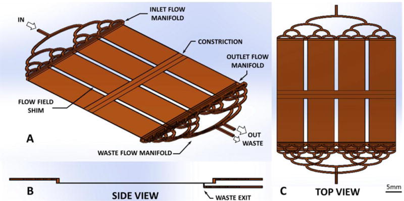
Blood flow path within high-gradient magnetic separator (A) isometric, (B) side, and (C) top view.
The performance of the device was evaluated using a non-pathogenic analog of malaria-infected blood, composed of a physiologic suspension of healthy RBCs (hRBCs) and methemoglobin RBCs (metRBCs) in a phosphate buffered saline (PBS). The ratio of metRBCs to hRBCs was chosen to reflect the concentration that occurs in severe malaria.
MATERIALS AND METHODS
Non-Pathogenic Malaria-Infected Blood Analog
To avoid the need of culturing Plasmodium falciparum-infected RBCs in the laboratory, an alternative blood analog was prepared using methemoglobin RBCs. These cells occur naturally in humans, although in very low amounts, and feature a high spin iron form similar to iRBCs. MetRBCs exhibit increased membrane rigidity also observed developing iRBCs6,37, are non-infectious, and have the added advantage of greater stability than iRBCs when stored properly38. These cells were prepared using fresh whole blood from consenting donors obtained via venipuncture with an IRB-approved protocol. The RBCs were washed three times in PBS (Sigma-Aldrich Corp., St. Louis, MO). The buffy coat and plasma were removed, then the RBCs were re-suspended in PBS to 50% hematocrit (Hct) with 1% v/v of Gentamycin. Solid NaNO2 (0.069 g per 1mL of RBC suspension) and 1X PBS (10mL per 1mL of RBC suspension) were vortexed together and then added to the RBC suspension. The mixture was incubated in a closed, rocked container at room temperature for 90 minutes, washed three additional times and stored at 4°C. The levels of metHb (methemoglobin) and HbO2 (oxyhemoglobin) were measured by hemoximetry (OSM-3, Radiometer, Brønshøj, Denmark).
Magnetic Force Field
A magnet array in combination with an adjacent ferromagnetic grid was designed to optimize the magnetic force within the flow passage of the device. The ferromagnetic grid was fabricated by photoetching a 125 μm thick sheet of 302 stainless steel (half hard) having an overall size of 60 mm × 60 mm. The dimensions of each of the wires of the grid was 200 μm with a pitch of 400 μm. Several configurations of permanent magnets were considered, based on commercially available neodymium N40 magnets (K&J Magnetics, Pipersville, PA, USA). These included a single monolithic magnet (76.2 mm wide × 12.7 mm thick), a set of three magnets (25.4 mm × 12.7 mm), five magnets (12.7 mm × 12.7 mm), nine magnets (6.3 mm × 6.3 mm) arranged in an alternating fashion, and a Hallbach configuration in which each subsequent magnet was rotated 90 degrees from the previous (i.e. ↑←↓→↑). The magnetic force field for these configurations was simulated in 2D using a finite element magnetics software package (FEMM, QinetiQ North America, Waltham, MA, USA). Fig. 3 provides an illustrative example of the magnetic field density using the single magnet.
FIGURE 3.

Simulated magnetic field density field (B) for the mesoscale HGMS device with a single 76.2 mm wide × 25.4 mm thick N40 permanent magnet in cross-section. The black dashed box indicates the flow domain where magnetic force was calculated.
The simulated magnetic field density, B, was discretized into a 5 μm by 5 μm mesh within the flow passage (100 μm across the entire 60 mm wide wire array) for each magnet arrangement. The magnetic gradient, dB/dx and dB/dy, was calculated by finite difference. The magnitude of the magnetic gradient was calculated using Equation 1 and averaged across the flow field for each magnet arrangement using Matlab (The MathWorks, Inc., Natick, MA, USA).
These results are summarized (Table 1) for each magnet array configuration. The five-magnet Hallbach array was found to produce greatest average magnetic gradient of 0.33×10⁻² T μm−1 with a local maximum of 5.7×10⁻² T μm−1. For comparison, previously reported experiments using a single magnet were able to concentrate metRBCs or late-stage iRBCs employing a magnetic gradient of the order 1×10⁻⁶ to 6×10⁻⁶ T μm−1 4,15.
TABLE 1.
Magnetic force across the mesoscale continuous HGMS device ferromagnetic wire array 1.5 mm away from six magnet array configurations.
| Magnet array configuration | Average |gradB| (10−2 T μm−1) |
|---|---|
| one 76.2 mm × 12.7 mm | 0.063 |
| three 25.4 mm × 12.7 mm (alternating) | 0.26 |
| five 12.7 mm × 12.7 mm (alternating) | 0.29 |
| five 12.7 mm × 12.7 mm (Hallbach) | 0.33 |
| nine 6.3 mm × 6.3 mm (alternating) | 0.22 |
| nine 6.3 mm × 6.3 mm (Hallbach) | 0.32 |
To minimize end effects, the width of the magnets was specified to be 27% wider than the flow field. These simulations also revealed that the magnitude of the magnetic gradient was not greatly sensitive to the distance separating the grid from the permanent magnet array. Conversely, the strength of the gradient was observed to drop off rapidly with distance from the grid into the flow path. These observations were used to guide the construction of the assembly, allowing the acrylic wall separating the magnet and grid to be 0.5 to 1.0 mm thick and the grid along the side of the flow passage adjacent to magnet array.
Flow Passage Optimization
The geometry of the central region of the flow path, illustrated in Fig. 2, was optimized previously by a numerical simulation study, published by Wu et al.35 Briefly, the simulation treated the malaria-infected blood as a multi-component system, comprised of “soft sphere” RBCs and paraRBCs in a Newtonian host fluid. The governing equations of motion were solved using computational fluid dynamics discrete element method (CFD-DEM) via OpenFOAM (OpenCFD Ltd., Bracknell, UK). This model permitted the motion of paramagnetic and non-magnetic RBCs in the HGMS flow path to be predicted. The objectives of these simulations were twofold: to assure effective stratification of paraRBCs near the bottom wall, and to optimize the removal of the paraRBC-enriched layer while preventing recirculation from the waste into the outlet path. The first objective was achieved by introducing an upstream constriction in the flow path. This had the effect of translocating the magnetic cells within the region of greatest magnetic gradient force adjacent to the ferromagnetic wire array. Downstream of the constriction, a diffuser allows the flow field to gradually expand, causing the magnetic cells to be trapped by the magnetic field, while the non-magnetic, healthy RBCs could escape. This expansion reduces disruptive cell-cell interactions from crowding at relatively high concentrations (i.e. physiological Hct).35 Wu et al. reported the optimal constriction-diffuser dimensions to be 2 mm long × 50 μm constriction followed by a 2 mm long diffuser35. A 20 mm long 100 μm separation area after the diffuser was included in the final device to ensure complete separation.
The second objective was achieved by choosing the width of the waste channel to achieve a compromise between throughput and clearance efficiency. Five different widths were evaluated: 1.0, 0.4, 0.1, 0.04, and 0.01 mm (Fig. 4). The larger slits were found to remove more infected cells overall, but at the expense of removing healthy cells as well. The smaller slits were better able to discriminate between cell types, but was limited in flow output. Therefore, the width of the waste exit was chosen as 0.04 mm.
FIGURE 4.

Simulation results comparing waste channel width of 1.0, 0.4, 0.1, 0.04, and 0.01 mm. Gray dots are hRBCs, black dots are iRBCs.
Additional simulations were performed to optimize the design of the inlet and outlet flow manifolds. The objective was to produce a wide, homogenous, laminar flow field within a short distance. This was necessary to transition from relatively small inlet/outlet ports (0.8 mm) to a wide rectangular flow passage (100 μm × 60 mm) while minimizing the overall length and avoiding dead volume to prevent sedimentation. A multi-level, orthogonal bifurcation manifold was adopted for this purpose (shown in Fig. 1 and 2). The design parameters included: channel width, number of bifurcations, and shape of transitions. The design was optimized through iterative computational fluid dynamic (CFD) simulations using commercial software (Fluent, ANSYS Inc., Canonsburg, PA, USA) (Fig. 5). The inlet flow was prescribed to be 77 μL min−1 to achieve a targeted centerline flow velocity of 0.3 mm s−1, chosen from average values in similar published continuous paraRBC microseparators12,22,28,31. The viscosity of blood was approximated to be 4 cP. The resulting manifold provided a satisfactory homogeneous a laminar flow field while limiting stagnant regions and simplifying fabrication with off-the-shelf materials. The average velocity at the manifold outlet was 0.29 mm s−1 corresponding to a Reynolds number of approximately 7.5×10⁻⁶.
FIGURE 5.
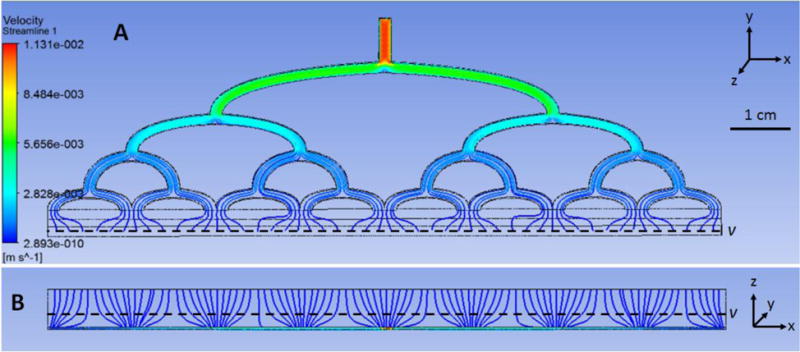
Velocity streamlines created via ANSYS within inlet manifold a) and b) bottom view.
Device fabrication
The device was constructed as layered stack of primarily flat components. The structural components were fabricated from cast acrylic (McMaster-Carr, Aurora, OH, USA) that were laser cut (Epilog Laser, Golden, CO, USA) and solvent bonded with dichloromethane. The flow manifolds were laser engraved into 3 mm thick cast acrylic pieces. The ferromagnetic wire array was photo-etched from 125 μm thick “half hard” stainless steel (SS410, Kemac Technology Inc., Azusa, CA, USA). The wire array was attached to the acrylic substrate (1.5 mm thick) using double-sided pressure sensitive adhesive tape (444, 3M, St. Paul, MN, USA). The waste exit was fashioned using two sections of polyethylene shim stock, separated by a temporary metal shims during assembly to achieve the desired width (40 μm) determined by CFD simulation, described above. To prevent accumulation of metRBCs in the interstices of the wire array they were filled with adhesive (Loctite 290 and 7469 Primer Henkel Corporation, Weirton, WV, USA) and carefully planed flat with a chisel blade. A quality control step was performed to ensure the planed surface was free of micron-sized irregularities and verified using a surface roughness tester (Surftest SJ-210, Series 178, Mitutoyo America Corporation, Aurora, IL, USA) using a 2 μm wide stylus head. Acceptable roughness was defined as mean roughness less than 5 μm and overall maximum less than 12 μm. The gasket enclosing the flow path was made from 100 μm thick polyethylene shim stock fabricated with a CNC cutting machine (Silhouette America, Lehi, Utah, USA). Three evenly-spaced 2 mm wide strips were placed longitudinally within the main flow channel to provide support and assure parallelism. The full assembly was sealed along all edges were with cyanoacrylate adhesive (Loctite 430, Henkel Corporation, Weirton, WV, USA) and reinforced with overlapping 0.8 mm thick acrylic strips. The constriction-diffuser step was incorporated into the center of the top plate using fast-drying nitrocellulose (Fig. 1d). It was formed using a precision ground zirconia drawdown bar (Dura-Metal Products Corp., Irwin, PA, USA) with the profile, described in Wu et al.35, cut around its circumference. A 2 mm margin at the edge of the plate was removed to accommodate the flow field shim. Fig. 1d shows the final device.
Experimental Setup
The full experimental setup for in-vitro verification of the mesoscale continuous HGMS device is shown in Fig. 6. The device and a 5 mL syringe were mounted to a laboratory rocker placed on a scissor jack. This reduced RBC sedimentation during the experiment. Within the syringe, a single 6 mm stainless steel ball bearing was placed to facilitate mixing. Rather than pressurize the inlet, a second syringe connected to the outlet was used to withdraw blood, creating a slight negative pressure within the channel, which helped maintain the seal of the flow path. The waste path was likewise drained by a third syringe. Both outlet and waste syringes were actuated by a precision syringe pump (Pump 33, Harvard Apparatus, Holliston, Massachusetts, USA).
FIGURE 6.

Experimental setup for the mesoscale continuous HGMS prototype verification.
The inlet syringe contained a mixture of metRBCs and hRBCs with an initial Hct of 30% (i.e. ratio of total volume of cells to suspending medium). The proportion of metRBCs was 20%. This mixture was chosen to mimic average clinical parameters reported for an anemic patient with severe hyperparasitemia3,5,7,11,17,18,34,39. The inlet flow rate (Qin) and flow split ratio (SR = Qwaste/Qin) were varied comprising eight experimental conditions in total (Table 2). All experiments were repeated in triplicate, with the exception of one condition which produced the best results which was performed 21 times. Between experiments, the volume of blood in the waste and outlet manifold were purged to avoid experimental artifact.
TABLE 2.
paraRBC removal efficiency (ηremoval) and hRBC rescue efficiency (ηrescue) results for verification experiments for the mesoscale continuous HGMS device in a single pass. n is sample size and SR is Qwaste/Qin (Q is flow).
| Condition # | n | flow rate Q (μL min−1) |
SR | removal
efficiency ηremoval |
rescue
efficiency ηrescue |
|---|---|---|---|---|---|
| 1 | 3 | 77 | 5% | 7.2±0.3% | 96.3±0.6% |
| 2 | 21 | 77 | 10% | 27.0±2.2% | 96.1±1.4% |
| 3 | 3 | 77 | 20% | 21.8±1.7% | 96.4±1.3% |
| 4* | 3 | 39 | 10% | * | * |
| 5 | 3 | 154 | 10% | 14.6±1.0% | 96.0±0.7% |
| 6 | 3 | 231 | 10% | 16.7±1.2% | 96.7±0.8% |
| 7 | 3 | 308 | 10% | 15.0±1.8% | 97.8±0.5% |
| 8 | 3 | 385 | 10% | 11.5±0.3% | 97.0±0.3% |
reasonable conservation of mass was not maintained
Blood samples were drawn at the inlet, waste and outlet at the beginning and end of the experiment and processed to measure Hct, %HbO2, %metHb, and %RHb (reduced hemoglobin) via a hemoximeter. Samples were randomly checked for hemolysis by visually qualifying plasma-free hemoglobin content in the supernatant. At the end of each experiment, the device was flushed in a 4-step procedure with 30 mL of PBS followed by 10% Tergazyme, 10% Simple Green, and distilled water in sequence. It was then dried with house air and stored at 4°C for later use.
Performance metrics
Two metrics were defined to evaluate the performance of the device: (1) the reduction of paraRBCs returned to the patient, paraRBC removal efficiency (ηremoval):
| [2] |
where Qin and Qout are the volumetric flow rate of blood in and out of the device, respectively, corresponding to blood withdrawn and returned to the patient (Fig. 2). For the verification results reported here, paraRBC = metRBC. [paraRBC] and [hRBC] are the concentrations of paraRBCs and healthy RBCs (%metHb*Hct and %HbO2*Hct), respectively. If Qout is zero, hence all blood flows into the waste, the removal efficiency will be 100% and corresponds to what is done in exchange transfusion. Therefore a second metric is needed to account for the rescue efficiency of healthy RBCs (hRBCs). (2) hRBC rescue efficiency (ηrescue), the percentage of healthy RBCs recovered in the outlet:
| [3] |
In addition to the above, the conservation of mass was verified to assess accumulation of cells within the device, e.g. due to sedimentation or magnetic trapping. Since the two efficiencies are somewhat at odds, one of the goals of this study was to determine an optimal combination of flow rate and split ratio to maximize paraRBC removal while preserving healthy RBCs.
RESULTS
Six separately prepared batches of metRBCs (approximately 30 mL each) were analyzed via hemoximetry resulting in 34.9±8.6% Hct, 0.2±0.0% HbO2, 98.1±0.3% metHb, and 0.8±0.3% RHb. The measured conservation of mass for each condition was within ±5% which was deemed within an acceptable range of error. The one exception was at the lowest flow rate tested (39 μL min−1) for 10% SR (condition 4), in which the conservation of mass was greater than −30% for metRBCs. This loss was believed to be caused by drag force being insufficient to prevent adhesion of metRBCs to the ferromagnetic wires leading to metRBC build-up in the device.
Averaged ηremoval and ηrescue values the control studies with no magnet varied from −3.0 to 3.1% with variation less than 1.9%, which was deemed within an acceptable range of error. The ηremoval and ηrescue results for the seven conditions in which a magnet was present are listed in Table 2. The condition that exhibited the best performance overall was for 77 μL min−1 at 10% SR (condition 3). In this case the reduction in metRBCs at the outlet was 27.0% ±2.2% for a single pass. The depletion of healthy RBCs at the outlet was negligibly small (ηrescue = 96.1±1.4%).
DISCUSSION
Several magnetic cell-sorting or cell-separating devices have been previously reported in the literature for a variety of applications. These can be classified into batch or flow-through devices. Further distinction can be made regarding the use of magnetic tags or labels. Of the reported label-free, flow-through devices, those most closely related to the device reported here are the microfluidic devices introduced independently by Nam et al.22, Han et al.12, and Qu et al.28 Nam et al. designed a microfluidic separator with a single nickel wire parallel to flow and two saline buffer layers parallel to the flow path edge to quickly clear captured target cells. This design enabled a high capture efficiency of early and late-stage iRBCs with ηremoval values of 98.3% for late stage iRBCs and 73% for early stage iRBCs22. Han et al. created a multi-step cascade separator with specially shaped electroplated nickel islands to efficiently collect deoxyRBCs (ηremoval = 93.5%) and white blood cells12. Qu et al. concentrated metRBCs along the centerline of a microfluidic field, with a single nickel wire sandwiched along the flow passage center parallel to flow, and collected the cells in the center of three outlet paths (ηremoval = 93.7%)28. Table 3 summarizes the specifications of the above three devices as compared to the device reported in this study. In addition to the published data, the table provides a comparison of the volumetric rate of removal of paraRBCs, i.e.:
| [4] |
TABLE 3.
Comparison of results to other HGMS devices for separation of paraRBCs.
| our device | Nam et al. | Han et al. | Qu et al. | ||
|---|---|---|---|---|---|
| paraRBC type | metRBC | early-stage iRBC |
late-stage iRBC |
deoxyRBC | metRBC |
| Qin (μL min−1) | 77 | 0.8 | 0.8 | 0.083 | 0.23 |
| total Hct | 30% | 0.3% | 0.3% | ~4% | ~1% |
| %paraRBC | 20% | 100% | 100% | 100% | 100% |
| ηremoval | 27.0% | 73.0% | 99.2% | 93.5% | 93.7% |
| QparaRBC (μL min−1) | 1.2 | 0.0018 | 0.0024 | ~0.0031 | ~0.0022 |
The greatest contributing factor towards the success of this device’s design is the maximized magnetic force created by the optimized magnetic wire array and magnet combination. The wire array features repeated magnetic poles with a filleted rectangular cross section that balances the benefits of a square pole, which creates large local forces at the sharp corners of the pole, and the far-reaching properties of a round pole. Additionally, the array pitch featured here enables constructive overlapping of magnetic forces between adjacent poles across the entire flow passage height and array. Although the reported removal efficiency of the current prototype is less than a third of other devices, the removal throughput is approximately 400 to 700 fold greater and provides the advantage of processing blood with physiological Hct. Unlike all other successful published continuous paraRBC HGMS devices, our device is non-dilutive and thus applicable to treatment applications where avoiding further diluting anemic patients is a critical concern. The throughput for these other devices would likely be significantly reduced due to increased cell-cell collisions with the introduction of healthy cells at physiological hematocrit. Furthermore, these microfluidic designs would not be amenable to up-scaling required to accommodate physiological blood flow required for treatment. Doing so would involve assembling hundreds of stacked PDMS microchannels with an integrated flow and magnet system which would present to be difficult, possibly prohibitive challenges with respect to fabrication and cost.
Limitations
The fabrication process of the prototype device, which is performed manually at present, could be improved and automated to reduce micron-scale imperfections which disturb the efficient margination of magnetic cells near the surface. The experiments presented here examined the effect of flow rate and split ratio, but were limited to a single hematocrit (30%) and concentration of paraRBCs (6%). This was chosen to represent the hematocrit of patients presenting with severe malaria. It is reasonable to expect that its efficiency would be reduced with more hemo-concentrated blood, and conversely the efficiency would be improved with diluted blood.
Additional independent factors that were not included in these studies that could potentially affect performance include hematocrit, temperature, RBC age, and proteins present in whole blood. A suspension of healthy and paramagnetic RBCs was used as substitute for whole blood to simplify experimental protocols and for the sake of expediency during the optimization (trial-and-error) process for designing this device. As a result, these experiments did not consider the potentially confounding roles of platelets and various plasma proteins. Future verification will be required with whole blood prior to clinical use. This in turn will consider the requirements for anti-coagulation and will potentially necessitate additional optimization of the device. An important factor is the magnetic susceptibility of the infected blood cells, which varies throughout the 48 hour intra-erythrocytic life cycle of the parasite. Because of the risk and difficulty associated with use of falciparum iRBC cultures, it is wise to continue optimizing the device with a non-pathogenic analog before transitioning to malaria-infected blood. Since the magnetic susceptibility of ring-stage iRBCs is over 2.5 times greater than metRBCs, clearance of iRBCs in future verification tests is expected to be greater than the results reported here.
Clinical Translation
Exchange transfusion (ET) for severe cases of malaria can require a very large volume of donor blood, usually between 500 and 10,000 mL per treatment27. To assess the efficacy of HGMS to reduce the need for donor blood, a first-order mathematical model was employed that computes the clearance of iRBCs from the circulation19. Briefly, the model applies first order rate equations were to simulate the concentration of healthy RBCs and infected RBCs due to contemporaneous addition of donor blood and drainage of circulating blood, assuming complete mixing. A patient-specific drug clearance and parasite growth term, based on published models33, was included to calibrate the model to published ET treatments. Fig. 7 shows the calibrated model applied to an anemic hyperparasitemic malaria patient described by Zhang et al.39, a 5 year old girl with initially 20% Hct and 40% parasitemia. The reported ET treatment relieved her anemia with a final Hct of 40% and reduced her parasitemia to 1% after 133 minutes of treatment using about 1120 mL of packed donor RBCs (4 units). Next, a hypothetical scaled-up version of the mesoscale device was introduced to the model, having the same iRBC clearance efficiency (27%) and hRBC rescue efficiency (96%) reported here, but capable of a flow rate similar to common continuous dialysis flow rates, 160 mL min−1. In this scenario, the ET rate was adjusted to achieve the same final Hct as the ET treatment (Fig. 7). As compared to the reported treatment time of approximately 130 minutes for ET, the addition of the continuous HGMS system achieved the same reduction of parasitemia in 65 minutes, yet requiring only 700 mL of donor packed RBC volume (3 units). This equates to 37% less donor blood in 51% less time than the reported ET treatment. In addition to the obvious benefits, decreased treatment time and consumption of donor blood also decreases the risk of fluid overload, transfusion reactions in patients, and transfection risk of other blood-borne diseases. With hoped improvements to the HGMS device, for example increasing the iRBC removal efficiency to, say, 40% halves the needed donor blood and reduces the duration of treatment by 60%. This model illustrates that the addition of HGMS, even at significantly less than perfect (100%) efficiency, could provide a substantial clinical benefits in settings where time and donor blood is scarce.
FIGURE 7.

Comparison of treatment of hypothetical malaria patient with and without HGMS. Black line indicates conventional exchange transfusion with drug therapy (black). The blue curve indicates the addition of HGMS. Blood volume replacement adjusted to achieve the same final hematocrit of 30% (■). Solid circle (●) indicates parasitemia reduced to 1%.
In summary, we presented a novel mesoscale continuous HGMS device for selective removal of paramagnetic RBCs from whole blood. The prototype device was experimentally verified using an iRBC analog having a physiological concentration of healthy and paramagnetic RBCs. It successfully removed 27% of paramagnetic metRBCs in a single pass without excessive loss of healthy RBCs at a rate of over 380 times greater than previously published microfluidic devices. Further improvements to the fluidic and magnet design are likely to provide improved performance. Future development will focus on scaling the device into a feasible treatment-scale system for severely ill malaria infected patients, providing an adjuvant to exchange transfusion which is faster and economizes the use of valuable donor blood.
Footnotes
CONFLICT OF INTEREST
No benefits in any form have been or will be received from a commercial party related directly or indirectly to the subject of this manuscript.
References
- 1.Ahn SY, Shin MY, Kim YA, Yoo JA, Kwak DH, Jung YJ, Jun G, Ryu SH, Yeom JS, Ahn JY, Chai JY, Park JW. Magnetic separation: A highly effective method for synchronization of cultured erythrocytic Plasmodium falciparum. Parasitol Res. 2008;102:1195–1200. doi: 10.1007/s00436-008-0893-8. [DOI] [PubMed] [Google Scholar]
- 2.Bhakdi SC, Ottinger A, Somsri S, Sratongno P, Pannadaporn P, Chimma P, Malasit P, Pattanapanyasat K, Neumann HPH. Optimized high gradient magnetic separation for isolation of Plasmodium-infected red blood cells. Malar J. 2010;9:38. doi: 10.1186/1475-2875-9-38. [DOI] [PMC free article] [PubMed] [Google Scholar]
- 3.Boctor FN. Red blood cell exchange transfusion as an adjunct treatment for severe pediatric falciparum malaria, using automated or manual procedures. Pediatrics. 2005;116:e592–5. doi: 10.1542/peds.2005-0314. [DOI] [PubMed] [Google Scholar]
- 4.Chikov V, Kuznetsov A, Shapiro A. Single cell magnetophoresis and its diagnostic value. J Magn Magn Mater 122. 1993;122:367–370. [Google Scholar]
- 5.Chotivanich K, Udomsangpetch R, Simpson JA, Newton P, Pukrittayakamee S, Looareesuwan S, White NJ. Parasite multiplication potential and the severity of Falciparum malaria. J Infect Dis. 2000;181:1206–9. doi: 10.1086/315353. [DOI] [PubMed] [Google Scholar]
- 6.Cranston H, Boylan C, Carroll G, Sutera S, Williamson J, Gluzman I, Krogstad D. Plasmodium falciparum maturation abolishes physiologic red cell deformability. Science. 1984;223:400–3. doi: 10.1126/science.6362007. [DOI] [PubMed] [Google Scholar]
- 7.Deshpande A, Kalgutkar S, Udani S. Red cell exchange using cell separator (therapeutic erythrocytapheresis) in two children with acute severe malaria. J Assoc Physicians India. 2003;51:925–926. [PubMed] [Google Scholar]
- 8.Furdui VI, Harrison DJ. Immunomagnetic T cell capture from blood for PCR analysis using microfluidic systems. Lab Chip. 2004;4:614–618. doi: 10.1039/b409366f. [DOI] [PubMed] [Google Scholar]
- 9.Graham MD. Efficiency comparison of two preparative mechanisms for magnetic separation of erythrocytes from whole blood. J Appl Phys. 1981;52:2578–2580. [Google Scholar]
- 10.Hackett S, Hamzah J, Davis TME, St Pierre TG. Magnetic susceptibility of iron in malaria-infected red blood cells. Biochim Biophys Acta - Mol Basis Dis. 2009;1792:93–99. doi: 10.1016/j.bbadis.2008.11.001. [DOI] [PubMed] [Google Scholar]
- 11.Hall A. Exchange transfusion and quinine concentrations in falciparum malaria. Br Med J. 1985;291:1169–1170. doi: 10.1136/bmj.291.6503.1169-a. [DOI] [PMC free article] [PubMed] [Google Scholar]
- 12.Han KH, Frazier AB. Paramagnetic capture mode magnetophoretic microseparator for high efficiency blood cell separations. Lab Chip. 2006;6:265–273. doi: 10.1039/b514539b. [DOI] [PubMed] [Google Scholar]
- 13.Iliescu C, Xu G, Barbarini E, Avram M, Avram A. Microfluidic device for continuous magnetophoretic separation of white blood cells. Microsyst Technol. 2009;15:1157–1162. [Google Scholar]
- 14.Kang JH, Krause S, Tobin H, Mammoto A, Kanapathipillai M, Ingber DE. A combined micromagnetic-microfluidic device for rapid capture and culture of rare circulating tumor cells. Lab Chip. 2012;12:2175. doi: 10.1039/c2lc40072c. [DOI] [PubMed] [Google Scholar]
- 15.Karl S, David M, Moore L, Grimberg BT, Michon P, Mueller I, Zborowski M, Zimmerman PA. Enhanced detection of gametocytes by magnetic deposition microscopy predicts higher potential for Plasmodium falciparum transmission. Malar J. 2008;7:66. doi: 10.1186/1475-2875-7-66. [DOI] [PMC free article] [PubMed] [Google Scholar]
- 16.Kong TF, Ye W, Peng WK, Hou HW, Marcos, Preiser PR, Nguyen N-T, Han J. Enhancing malaria diagnosis through microfluidic cell enrichment and magnetic resonance relaxometry detection. Nat Sci Reports. 2015;5:1–12. doi: 10.1038/srep11425. [DOI] [PMC free article] [PubMed] [Google Scholar]
- 17.Kramer SL, Campbell CC, Moncrieff RE. Fulminant Plasmodium falciparum infection treated with exchange blood transfusion. J Am Med Assoc. 1983;249:244–245. doi: 10.1001/jama.1983.03330260062034. [DOI] [PubMed] [Google Scholar]
- 18.Macallan DC, Pocock M, Bishop E, Bevan DH, Parker-Williams J, Harrison T, Robinson GT. Automated erythrocytapheresis in the treatment of severe falciparum malaria. J Infect. 1999;39:233–6. doi: 10.1016/s0163-4453(99)90056-7. [DOI] [PubMed] [Google Scholar]
- 19.Martin AB, Antaki JF. Comparison of Clearance of Malaria-infected Erythrocytes by Exchange Transfusion and High Gradient Magnetic Apheresis. 2017 [Google Scholar]
- 20.Melville D, Paul F, Roath S. Direct magnetic separation of red cells from whole blood. 1975 doi: 10.1038/255706a0. [DOI] [PubMed] [Google Scholar]
- 21.Nalbandian RM, Sammons DW, Manley M, Xie L, Sterling CR, Egen NB, Gingras BA. A Molecular-based Magnet Test for Malaria. Am J Clin Pathol. 1995;103:57–64. doi: 10.1093/ajcp/103.1.57. [DOI] [PubMed] [Google Scholar]
- 22.Nam J, Huang H, Lim H, Lim C, Shin S. Magnetic separation of malaria-infected red blood cells in various developmental stages. Anal Chem. 2013;85:7316–7323. doi: 10.1021/ac4012057. [DOI] [PubMed] [Google Scholar]
- 23.Oka T, Kanayama H, Fukui S, Ogawa J, Sato T, Ooizumi M, Terasawa T, Itoh Y, Yabuno R. Application of HTS bulk magnet system to the magnetic separation techniques for water purification. Phys C Supercond its Appl. 2008;468:2128–2132. [Google Scholar]
- 24.Owen CS. High gradient magnetic separation of erythrocytes. Biophys J. 1978;22:171–8. doi: 10.1016/S0006-3495(78)85482-4. [DOI] [PMC free article] [PubMed] [Google Scholar]
- 25.Pamme N, Wilhelm C. Continuous sorting of magnetic cells via on-chip free-flow magnetophoresis. Lab Chip. 2006;6:974. doi: 10.1039/b604542a. [DOI] [PubMed] [Google Scholar]
- 26.Paul F, Roath S, Melville D, Warhurst DC, Osisanya JOS. Separation of malaria-infected erythrocytes from whole blood: use of a selective high-gradient magnetic separation technique. Lancet. 1981;318:70–71. doi: 10.1016/s0140-6736(81)90414-1. [DOI] [PubMed] [Google Scholar]
- 27.Phillips P, Nantel S, Benny W. Exchange transfusion as an adjunct to the treatment of severe falciparum malaria. Rev Infect Dis. 1990;12:1100–1108. doi: 10.1093/clinids/12.6.1100. [DOI] [PubMed] [Google Scholar]
- 28.Qu BY, Wu ZY, Fang F, Bai ZM, Yang DZ, Xu SK. A glass microfluidic chip for continuous blood cell sorting by a magnetic gradient without labeling. Anal Bioanal Chem. 2008;392:1317–1324. doi: 10.1007/s00216-008-2382-4. [DOI] [PubMed] [Google Scholar]
- 29.Ribaut C, Berry A, Chevalley S, Reybier K, Morlais I, Parzy D, Nepveu F, Benoit-Vical F, Valentin A. Concentration and purification by magnetic separation of the erythrocytic stages of all human Plasmodium species. Malar J. 2008;7:45. doi: 10.1186/1475-2875-7-45. [DOI] [PMC free article] [PubMed] [Google Scholar]
- 30.Sherman IW. Amino acid metabolism and protein synthesis in malarial parasites. Bull World Health Organ. 1977;55:265–276. [PMC free article] [PubMed] [Google Scholar]
- 31.Takayasu M, Duske N, Ash SR, Friedlaender FJ. HGMS studies of blood cell behavior in plasma. IEEE Tr. 1982;18:1520–1522. [Google Scholar]
- 32.Trang DTX, Huy NT, Kariu T, Tajima K, Kamei K. One-step concentration of malarial parasite-infected red blood cells and removal of contaminating white blood cells. Malar J. 2004;3:7. doi: 10.1186/1475-2875-3-7. [DOI] [PMC free article] [PubMed] [Google Scholar]
- 33.White N. The parasite clearance curve. Malar J. 2011;10:278. doi: 10.1186/1475-2875-10-278. [DOI] [PMC free article] [PubMed] [Google Scholar]
- 34.World Health Organization. Guidelines for the treatment of malaria. Geneva: 2006. [Google Scholar]
- 35.Wu WT, Martin AB, Gandini A, Aubry N, Massoudi M, Antaki JF. Design of microfluidic channels for magnetic separation of malaria-infected red blood cells. Microfluid Nanofluidics. 2016;20:1–11. doi: 10.1007/s10404-016-1707-4. [DOI] [PMC free article] [PubMed] [Google Scholar]
- 36.Xia N, Hunt TP, Mayers BT, Alsberg E, Whitesides GM, Westervelt RM, Ingber DE. Combined microfluidic-micromagnetic separation of living cells in continuous flow. Biomed Microdevices. 2006;8:299–308. doi: 10.1007/s10544-006-0033-0. [DOI] [PubMed] [Google Scholar]
- 37.Zavodnik IB, Lapshina EA, Rekawiecka K, Zavodnik LB, Bartosz G, Bryszewska M. Membrane effects of nitrite-induced oxidation of human red blood cells. Biochim Biophys Acta. 1999;1421:306–316. doi: 10.1016/s0005-2736(99)00136-4. [DOI] [PubMed] [Google Scholar]
- 38.Zborowski M, Ostera GR, Moore LR, Milliron S, Chalmers JJ, Schechter AN. Red blood cell magnetophoresis. Biophys J. 2003;84:2638–2645. doi: 10.1016/S0006-3495(03)75069-3. [DOI] [PMC free article] [PubMed] [Google Scholar]
- 39.Zhang Y, Telleria L, Vinetz JM, Yawn D, Rossmann S, Indrikovs AJ. Erythrocytapheresis forPlasmodium falciparum infection complicated by cerebral malaria and hyperparasitemia. J Clin Apher. 2001;16:15–18. doi: 10.1002/jca.1002. [DOI] [PubMed] [Google Scholar]
- 40.World Malaria Report. 2015