Abstract
Objective
In this work, a prototype of an effective electromagnet with a field-of-view (FoV) of 140 mm for neonatal head imaging is presented. The efficient implementation succeeded by exploiting the use of steel plates as a housing system. We achieved a compromise between large sample volumes, high homogeneity, high B0 field, low power consumption, light weight, simple fabrication, and conserved mobility without the necessity of a dedicated water cooling system.
Materials and methods
The entire magnetic resonance imaging (MRI) system (electromagnet, gradient system, transmit/receive coil, control system) is introduced and its unique features discussed. Furthermore, simulations using a numerical optimization algorithm for magnet and gradient system are presented.
Results
Functionality and quality of this low-field scanner operating at 23 mT (generated with 500 W) is illustrated using spin-echo imaging (in-plane resolution 1.6 mm × 1.6 mm, slice thickness 5 mm, and signal-to-noise ratio (SNR) of 23 with a acquisition time of 29 min). B0 field-mapping measurements are presented to characterize the homogeneity of the magnet, and the B0 field limitations of 80 mT of the system are fully discussed.
Conclusion
The cryogen-free system presented here demonstrates that this electromagnet with a ferromagnetic housing can be optimized for MRI with an enhanced and homogeneous magnetic field. It offers an alternative to pre-polarized MRI designs in both readout field strength and power use. There are multiple indications for the clinical medical application of such low-field devices.
Keywords: Electromagnet, Neonatal MRI, Structural steel housing, Biplanar gradient system, Low-field MRI
Introduction
In the last 10 years, the interest in lower polarizing fields (B0) has steadily increased and the market for them is rapidly expanding [1–11]. The advantages of low B0 fields are inviting: there are fewer susceptibility artifacts and a higher T1 contrast compared with higher B0 fields. Furthermore, these systems are usually less complex and do not require a superconducting magnet, which reduces the costs tremendously. Common low-field magnetic resonance imaging (MRI) systems operating with B0 fields in the μT and mT range use prepolarizing techniques to enhance signal-to-noise ratio (SNR) [3–11]. Systems without prepolarizing techniques operate primarily with higher B0 fields (>200 mT) [1, 12] and mostly use permanent or superconducting magnets for generating higher B0 fields. In this work, the B0 field was generated using a specially designed electromagnet. A B0 field of 23 mT without prepolarizing techniques was achieved, and the limitations of such a system and its possible applications were investigated.
A prototype of an effective electromagnet with a field of view (FoV) of 14 cm and a simulated homogeneity of ±40 ppm (at 10 cm) for low-field MRI was constructed. Effective implementation succeeded through the unique use of steel plates as a housing system. This setup increased the effectiveness of the B0 field and eliminated adjacent stray fields. The steel housing serves as a magnetic return circuit, amplifies the generated B0 field, and simultaneously provides several opportunities for shimming (e.g., by using permanent magnets on the outer and inner sides of the housing). In addition, the housing effectively shields interferences and comprises a stable mounting suspension of the magnet coils and gradient system. Another special feature is the compact design of the gradient coil system, which is embedded within the magnet coils and therefore does not require additional space. The system operates at a B0 field strength of 23 mT (965 kHz) generated by a 500 W amplifier. Our goal was to build a low-cost MRI prototype that can handle the minimum requirements of neonatal head imaging. The size of this desktop magnet is designed for premature infants. Simulations and measurements are shown—which illustrate the functionality and quality of this imaging system—using a sample diameter of 100 mm. Additional space is provided for optional correction coils (higher-order shimming) and cooling facilities (water cooling) in order to increase homogeneity and allow for higher performance when needed. The advantages of mobility and the cost-effective production are additional assets of the presented concept.
Materials and methods
Structural steel housing
Using structural steel (S235JR) as housing to return the magnetic flux effectively led to enhancement of the magnetic field (B0) [13]. The stray fields were minimized, and the housing was used as a solid mounting suspension (e.g., similar to an iron yoke of a c-shaped permanent magnet [14]). In addition, external interference signals were effectively shielded. Hence, there is no need to provide a magnetically shielded room. The steel housing (Fig. 1) can be closed completely or flexibly opened on each side of the walls. One front plate across from the connection panel was removed for all measurements (access 20 × 30 cm). For cost-effective production, the eight side walls and bottom/top plates are designed identically.
Fig. 1.
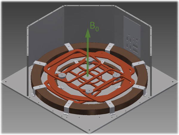
Overview of system geometries: computer-aided design (CAD) of the underpart of the magnet (donut geometry in brown) with the immersed biplanar gradient system (orange) mounted on a steel housing with 750 mm × 750 mm × 300 mm (botton plate) and a thickness of 10 mm (connection panel can be seen in the background). Arrow indicated generated B0 field direction aligned perpendicular to the arrangement. The front plates and the top cover are hidden
Magnet design
Magnetic field mapping simulations of the magnet design with the steel housing can be seen in Fig. 2. A compact, biplanar, double-donut design was implemented that enabled us to use horizontally aligned radio frequency (RF) solenoidal coils for signal transmission and reception (Tx/Rx). Furthermore, a biplanar gradient system could be integrated within the B0 field coils, avoiding additional loss of space in magnet volume (Fig. 1).
Fig. 2.
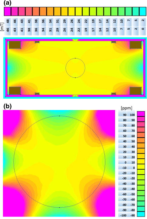
a B0 field mapping simulation of the magnet with steel housing (cross-section 750 mm × 300 mm with wall thickness of 10 mm, magnet coils in brown) and the legend numbered in mT with a delta of 2.4 mT for each color. b Magnified field-mapping simulation shows the fundamental homogeneity of the design. The legend is numbered in ppm with a delta of 10 ppm for each color. The black circle marks the magnet sweet spot with a diameter of 100 mm
All electromagnetic field calculations were performed using finite element method magnetics (FEMM; author David Meeker, http://www.femm.info). Optimizations based on FEMM calculations were conducted using a home-written script in MATLAB (Mathworks Inc.). Geometry shown in Fig. 2a were calculated using a simulated annealing algorithm [15, 16]. Optimum setup comprises two donut rings—the larger for generating the main magnetic field and the smaller for a correction field. Hence, the current of the outer ring is 3.2 times larger and should have an opposite polarity to the current of the inner ring. The minimum gap size (height) of the system was set to a fixed value of 200 mm. The algorithm varied the proportions of the donut rings for optimized magnet geometry. The quality function [15] of the algorithm was composed of the homogeneity and strength of the magnetic field within a defined FoV of 140 mm. The magnet and gradient coils were wound with enameled copper wire (diameter 2.8 mm) and molded with thermally conductive epoxy resin (Fig. 3). In addition, the contact surfaces of the B0 field coils were thermally connected with heat-conducting paste to ensure more heat transfer to the housing. The gradient coils were fixed at four mounting points as one unit (X, Y, Z gradient plates) and connected to the housing with polyvinyl chloride (PVC) screws.
Fig. 3.
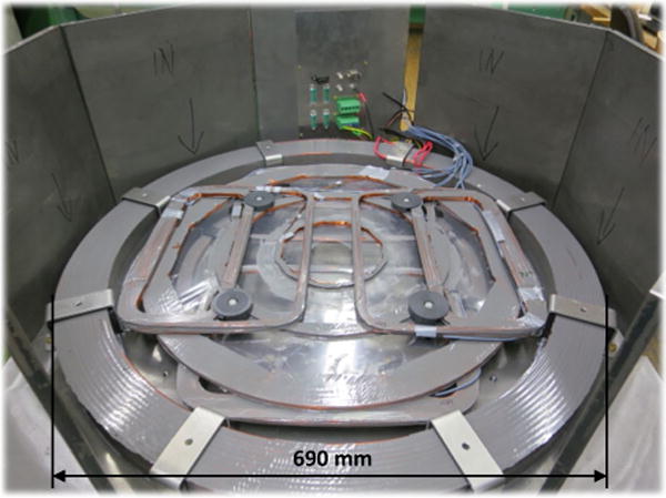
Components with mounting parts: bottom part of the magnet coils with the immersed biplanar gradient system mounted on a steel housing (connection panel in background)
Mounting brackets of the B0 coils have a 5 to 10 mm tolerance, which align the coils optimally (permitting shimming). The large B0 coils have 300 turns, yielding a total wire weight of 33 kg and a resistance of 1.6 Ω. The height of the small B0 coils (correction coils, 80 turns, each 2 kg, with 0.95 Ω) is 10 mm and of the large coils 40 mm (see geometry in Fig. 2a). This allowed the 30 mm thick gradient plates (X, Y, Z) to be completely integrated within the height of the B0 field coils. The copper weight of all B0 field coils together is 70 kg and the steel housing 150 kg. The entire system was put onto a table trolley, and the total weight of all devices and components (table trolley, magnet, power amplifier, gradient system, console, etc.) was <300 kg.
The two chosen power supplies—one for the large B0 coils (60 V/50 A, QPX1200, Aim-TTi) and one for the small correction coils (12 V/3 A, VLP-2403 PRO, Voltcraft), did not have sufficient current stabilization. This was addressed with an additional (handmade) current controller with linear voltage regulators (LT1083, Linear Technology) designed to stabilize power supplies within a few ppm. This regulation had a drift of 1 Hz/s that could be compensated by an automated frequency drift correction during measurements. Operation at 23 mT was chosen so as not to exceed a power consumption of 500 W. At that power, air cooling was sufficient to keep B0 field coil core temperature <50 °C when in continuous operation. Additional space was designed for an optional water cooling system that would support a B0 field of up to 80 mT. Our calculations indicate power dissipation for 50 mT would be 2 kW and for 80 mT 5 kW; water cooling would be required >500 W.
Gradients
Many different gradient designs have been developed with a wide range of size and complexity [10, 17, 18]. The most widespread gradient designs are cylindrical and optimized for axially aligned B0 field directions. The standard gradient system consists of two Golay coils [19] (x and y gradient fields) and one Maxwell coil [20, 21] (z gradient field). To keep the usable space as large as possible, a biplanar gradient system [22–25] that fits within the donut geometry of the B0 field magnet was chosen (Fig. 1).
The newly developed gradient system was integrated within the given magnet coils, with a gradient field linearity of 5 % within a sphere of 140 mm in the center of the device and a minimum gap of 200 mm. The geometry shown in Fig. 4 was calculated using simulated annealing algorithm [15, 16]. The algorithm varied the proportions of wires on the planar surface to keep the coil geometry within the given boundary conditions. Quality function [15] of the algorithm was composed of gradient field linearity and strength. Magnetic field simulations were based on the Biot–Savart law.
Fig. 4.
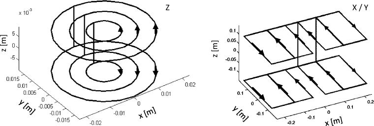
Simulation results of discrete current paths of X, Y and Z gradient. The Y gradient is not shown, as X is identical to Y (rotated 90° around the Z-axis). The connecting lines between gradient plates (top and bottom) are the back and return lines of the individual coil packs and thus do not provide any field input. Current directions are marked with arrows, and the gap was set to 230 mm
These current paths (Fig. 4) were used as templates to determine the actual winding geometry. The maximum size of the gradient system was determined from the inner coil diameter of the large B0 field coil of 570 mm. The external dimension for the Z gradient was 460 mm and for the X, Y gradient 475 mm × 230 mm. Maximum gradient field strengths of 27, 29, and 48 mT/m (x, y and z) at 5 A could be achieved. The thickness of each gradient coil was set to a maximum of 10 mm to ensure that the available space of 30 mm within the B0 field coil was not exceeded and that the gradient system could be completely contained within the vertical height for maximal space savings. The cross-section and number of turns of the copper wire were adjusted for the gradient amplifier (DC-600, Pure Devices GmbH, Wuerzburg, Germany). Therefore, each gradient was designed to a resistance of 10–13 Ω with an inductance of 25–36 mH to achieve slew rates of 50–150 T/m/s.
Transmit/receive coil
A Tx/Rx coil for the Larmor frequency of 965 kHz was built with an inner diameter of 100 mm and a matched quality factor of 95. The quality factor was measured inside (Q = 95) and outside (Q = 100) the magnet to measure the influence of the steel housing. This coil was wound as a solenoid using two parallel Litz wire assemblies with 45 strands each (enameled copper 2 × 45 × 0.1 mm), which were tuned and matched.
Field measurement of the magnet
A standard field-mapping method was used [22, 26, 27] to characterize the B0 to determine the local field strength introduced by the inhomogeneity of the magnet. Therefore, two measurements were carried out with two different echo times (ΔTE = 1 ms), and their phase images were subtracted to determine information of the resulting gradient (Fig. 5). A spherical oil phantom with 93 mm diameter was inserted in the center of the magnet, and a slice through the center of the oil phantom and the isocenter of the magnet was acquired. Imaging parameters were as follows: FoV 100 mm × 100 mm, bandwidth 500 Hz, TE = 20 ms, TR = 100 ms, slice thickness 20 mm, and one average. Sequence control and data acquisition of all measurements were conducted using an MR console Drive L (Pure Devices).
Fig. 5.
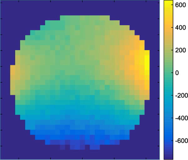
B0 field map of the constructted magnet; isocenter cross-section as in Fig. 2. The color map shows inhomogeneity in ppm. Imaging parameters: field of view (FoV) 100 mm × 100 mm, bandwidth 500 Hz, TE = 20 ms, TR = 100 ms, slice thickness 20 mm, and no averages
Results
B0 field mapping
All B0 field map pixels with a signal intensity <20 % of maximum signal amplitude of the signal were discarded and are shown in dark blue Fig. 5. Measurement ranges were ±600 ppm on the edges of the oil phantom. In comparison, simulation results (Fig. 2) showed a homogeneity of <|±40| ppm. The measurement was performed without first-order shimming using the gradient system.
Imaging experiment
The 2D spin-echo measurement (Fig. 6) shows the system’s imaging capability (magnet, gradient system, Tx/Rx coil, control system). The imaging parameters of the sequence used were TE = 40 ms, TR = 400 ms, FoV = (100 × 100) mm, BW = 100 Hz, and matrix size 64 × 64. Due to zero filling by a factor of two, the in-plane pixel resolution was 0.8 mm × 0.8 mm. With a phase oversampling factor of two and 32 averages, acquisition time was 29 min, with an SNR of 23. The maximum gradient strength was 2.5 mT/m.
Fig. 6.
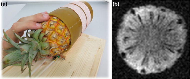
a The rf-coil of 100 mm diameter using a baby pineapple as a sample. b 2D spin-echo image of the pineapple with 5 mm slice thickness and matrix size 64 × 64 voxels
Discussion
We have developed an efficient electromagnet and a compact gradient set for low-field MR imaging composed of a steel housing with copper coils. The housing is mainly used for field enhancement and homogenization. The overall system forms a compromise between large sample volumes, high homogeneity, high B0 field, low power consumption, light weight, simple fabrication, and conserved mobility without the necessity of a dedicated water cooling system.
Homogeneity/large sample volume
Simulation homogeneity (Fig. 2) can be quantitatively compared with the measurement (Fig. 5). The simulation estimated a 15 × more homogeneous field compared with the nonshimmed (no first-order shim with gradient system) magnet measurement. The two main reasons for these deviations are due to the following real conditions that were not considered in the simulation.
First, the manufacturing tolerance of the entire magnetic structure were not taken into account, and the purity of the structural steel (S235JR) used for the housing was subject to production-related variations in quality (DIN EN 10025) that influence homogeneity.
Second, adjustment of the relative currents of the power source could not arbitrarily be accurately set. The drift of the two separately driven currents is different (one for the large B0 coils and one for the small correction coils), which limited the adjustability of the optimal current ratio. However, the existing inhomogeneity and current drifts still permit a level of acceptable imaging quality (Fig. 6). The fact that no complex homogenizing arrangements have been applied (such as no determined placement of shimming platelet/magnets, no exact adjustment of B0 coil currents, and no higher-order shimming coils) shows that there is still potential for more spatial homogeneity and therefore larger sample volumes. For this reason, and according to simulation results, we estimate that it is realistic to increase the spherical volume to a diameter of 140 mm or maybe even more. This will be explored in future experiments.
Efficiency
The magnet design comprises a well-balanced weight/performance ratio for the given field strength. The additional weight of the steel housing increased the magnetic field in rough proportion to the weight increase. The steel replaces more expensive copper, achieving a relatively similar field strength (copper is ten times more expensive than steel). At a similar B0 field strength, less power is needed in the presence of such high magnetic susceptibility housing; thus, at a constant total weight, magnetic efficiency increases. For instance, the B0 field decreases from 23 to 6 mT when calculated for the same coil geometry but in the absence of the steel housing.
The side parts of the housing can all be taken out individually. Note that in our data only one wall was removed. The omission of a single wall had no measurable impairment of homogeneity, shielding effect of stray fields, or interference from external signals. Only the B0 field was decreased by 5 kHz when opening one side wall. This was tested by additional experiments, which demonstrated that the 5-gauss contour was measured <1 cm from the steel construction and <10 cm in front of one open steel plate. Since the wavelength at the measurement frequency of 965 kHz was 311 m, access through a single open panel (20 × 30) cm is ~1000× smaller than the wavelength. This results in nonmeasurable deviations of RF shielding and implies that it would be possible to remove two or four walls (front, rear and side walls, not experimentally tested) to increase access to the sample without critically compromising field strength or homogeneity. The removed side walls should be placed parallel to the remaining side walls to double the thickness for unimpeded magnetic flux and avoid saturation of the material in the remaining walls. Our design thus offers considerable patient access via the side wall for future human imaging.
B0 field limitation/eddy currents
For the currently used field strength of 23 mT and a power dissipation of 500 W, a simple air cooling system is sufficient. The magnet was designed to operate with an even more powerful power supply assuming heat generated from the additional power consumption could be dissipated. With standard water cooling, a field strength of 50 mT (2 kW) could be reached. As the steel in the casing was starting to saturate at a field strength of ~100 mT, an upper limit of 80 mT for the current system was determined from simulation results. Beyond this field strength, no controlled magnetic flux can be ensured.
In addition, power dissipation increases to 5 kW at a magnetic field of 80 mT, which could still be dissipated by an industrial water cooling system. Apart from thermal dissipation, it is theoretically possible to operate with field strengths well above 100 mT. In those cases, corners must be fortified with additional steel to prevent magnetic field saturation and to maintain undisturbed magnetic flux. Alternatively, the wall thickness of the housing could be uniformly increased, with the disadvantage of a substantial weight increase.
In the setup used in this study, maximum gradient fields (x, y, z) of 27, 29, and 48 mT/m were realized. A typical 2D spin-echo sequence for the assembled system operating at a B0 field of 23 mT required only a small fraction (3 mT/m) of the maximum available gradient strength. Therefore, the existing gradient set would already be well suited for a B0 field of 80 mT. Because of the steel housing and the close proximity of the gradient system, eddy currents can be expected. This influence can be reduced by appropriate sequence selection with slow gradient ramp times. A 1 ms ramp time was used (Fig. 6), and no eddy current artifacts could be seen. If sequences more sensitive to the eddy current were to be used, actively shielded gradients could be employed to minimize these problems. Other alternatives, for example, could be a slotted steel housing, or the area near the gradient coils could be replaced by ferrite plates [28].
Image quality
The 2D spin-echo image (Fig. 6) shows the imaging functionality of the entire system (magnet, gradient system, Tx/Rx coil, control system). The in-plane resolution of 1.6 mm × 1.6 mm and slice thickness of 5 mm complies with the requirements of standard clinical criteria for routine diagnostic imagery. Previous work in low-field MRI measurements showed comparable results [31], with a prepolarization setup at 0.1 T [32, 33]. In our work, the spin-echo sequence was not optimized for fast imaging, and thus, significant improvements could be achieved. Rapid sequences, such as a multi-spin-echo (MSE) or true fast imaging with steady-state precession (true-FISP) sequence, which produce excellent imaging quality in low-field MRI [34], would allow for a substantial reduction in recording time of a comparable image shown in Fig. 6.
One of the biggest advantages of the overall design of the magnet described here is the ability to use a solenoid for the Tx/Rx coil, as this concept represents the most effective geometry [29] for an MRI coil, leaving room for improvement in future designs. For example, the strand diameter of 0.1 mm could be smaller for this frequency, the number of strands could be increased, and with some spacing between the turns, the Q factor would be increased [30].
Future applications
For many conditions, ruling out the presence of a substantial intracranial hemorrhage requiring surgical evacuation following trauma or stroke, diagnosing a tumor in which fine imaging details may not affect surgical treatment, or diagnosing hydrocephalus, lower-field imaging may render equivalent patient outcomes at substantial cost savings. In the neonate, hemorrhage and hydrocephalus are the most common conditions of the brain requiring intervention. Hydrocephalus is the easiest clinical condition to resolve with MRI, since only contrast between brain and fluid is required. For accurate diagnosis of the location of fluid collections in relationship to the brain, an isotropic spatial resolution of 2 to 3 mm in the x–y plane and 5 to 10 mm in the z plane is necessary [35, 36]. The minimum FoV that would admit such infant heads would be within the 14-cm-diameter range, discussed in this report. Our measurements imply that minimum specifications were achieved for diagnostic neonatal infant head imaging with this prototype.
Our approach, and that of recent improvements in pre-polarized MRI configurations [37], are all examples of imaging in the mT range that may be capable of diagnostic quality for clinical use. We believe that such low-field technology can be further developed to bring the advantages of MRI diagnostics to the developing world, where the majority of people are without the benefit of access to MR imaging.
Conclusion
In this paper, we present a low-cost and compact electromagnet that consists of a steel housing with copper coils. The housing was used for field enhancement, homogenization, and shielding. This concept ensures a compromise between large sample volumes, high homogeneity, high B0 field, low power consumption, light weight, simple fabrication, and conserved mobility, without the necessity of a dedicated water cooling system. Our device is a further step toward clinically viable low-field imaging.
Acknowledgments
We thank Toni Drießle for helpful discussions and permanently valuable engineering inputs.
Footnotes
Compliance with ethical standards
Conflict of interest The authors declare that they have no conflict of interest.
Ethical standards This article does not contain any studies with human or animal subjects.
References
- 1.Blümich B, Casanova F, Appelt S. NMR at low magnetic fields. Chem Phys Lett. 2009;477(4–6):231–240. [Google Scholar]
- 2.Stepisnik J, Erzen V, Kos M. NMR imaging in the earth’s magnetic field. Magn Reson Med. 1990;15(3):386–391. doi: 10.1002/mrm.1910150305. [DOI] [PubMed] [Google Scholar]
- 3.Mohoric A, Planinsic G, Kos M, Duh A, Stepisnik J. Magnetic resonance imaging system based on earth’s magnetic field. Instrum Sci Technol. 2004;32(6):655–667. [Google Scholar]
- 4.Mohoric A, Stepisnik J, Kos K, Planinsic G. Self-diffusion imaging by spin echo in earth’s magnetic field. J Magn Reson. 1999;136(1):22–26. doi: 10.1006/jmre.1998.1594. [DOI] [PubMed] [Google Scholar]
- 5.Appelt S, Kühn H, Häsing W, Blümich B. Chemical analysis by ultrahigh-resolution nuclear magnetic resonance in the earth’s magnetic field. Nat Phys. 2006;2:105–109. [Google Scholar]
- 6.Appelt S, Häsing FW, Kühn H, Perlo J, Blümich B. Mobile high resolution xenon nuclear magnetic resonance spectroscopy in the earth’s magnetic field. Phys Rev Lett. 2005;94(19):197602. doi: 10.1103/PhysRevLett.94.197602. [DOI] [PubMed] [Google Scholar]
- 7.Halse ME, Coy A, Dykstra R, Eccles C, Hunter M, Ward R, Cal-laghan PT. A practical and flexible implementation of 3D MRI in the earth’s magnetic field. J Magn Reson. 2006;182(1):75–83. doi: 10.1016/j.jmr.2006.06.011. [DOI] [PubMed] [Google Scholar]
- 8.Kegler C, Seton HC, Hutchison JMS. Prepolarized fast spin-echo pulse sequence for low-field MRI Magnetic Resonance in Medicine. Magn Reson Med. 2007;57(6):1180–1184. doi: 10.1002/mrm.21238. [DOI] [PubMed] [Google Scholar]
- 9.Savukov I, Karaulanov T, Castro A, Volegov P, Matlashov A, Urbatis A, Gomez J, Espy M. Non-cryogenic anatomical imaging in ultra-low field regime: hand MRI demonstration. J Magn Reson. 2011;211(2):101–108. doi: 10.1016/j.jmr.2011.05.011. [DOI] [PMC free article] [PubMed] [Google Scholar]
- 10.Lother S, Hoelscher U, Kampf T, Jakob P, Fidler F. 3D gradient system for two B0 field directions in Earth´s field MRI. Magn Reson Mater Phy. 2013;26(6):565–573. doi: 10.1007/s10334-013-0376-5. [DOI] [PubMed] [Google Scholar]
- 11.Matter NI, Scott GC, Venook RD, Ungersma SE, Grafendorfer T, Macovski A, Conolly SM. Three-dimensional prepolarized magnetic resonance imaging using rapid acquisition with relaxation enhancement. Magn Reson Med. 2006;56(5):1085–1095. doi: 10.1002/mrm.21065. [DOI] [PubMed] [Google Scholar]
- 12.Savnik A, Malmskov H, Thomsen HS, Bretlau T, Graff LB, Nielsen H, Danneskiold-Samsøe B, Boesen J, Bliddal H. MRI of the arthritic small joints: comparison of extremity MRI (0.2 T) vs high-field MRI (1.5 T) Eur Radiol. 2001;11(6):1030–1038. doi: 10.1007/s003300000709. [DOI] [PubMed] [Google Scholar]
- 13.Feynman R, Leighton R, Sands M. The Feynman lectures on physics. II. Addison-Wesley; 2006. Reading. (Chapter 37: Magnetic Materials) [Google Scholar]
- 14.Wright SM, Brown DG, Porter JR, Spence DC, Esparza E, Cole DC, Huson FR. A desktop magnetic resonance imaging system. Magn Reson Mater Phy. 2002;13(3):177–185. doi: 10.1007/BF02678594. [DOI] [PubMed] [Google Scholar]
- 15.Dueck G, Scheuer T. Threshold accepting: a general purpose optimization algorithm appearing superior to simulated annealing. J Comput Phys. 1990;90(1):161–175. [Google Scholar]
- 16.Kirkpatrick S, Gelatt CD, Vecchi MP. Optimization by simulated annealing. Science. 1983;220(4598):671–680. doi: 10.1126/science.220.4598.671. [DOI] [PubMed] [Google Scholar]
- 17.Hidalgo-Tobon SS. Theory of gradient coil design methods for magnetic resonance imaging. Concepts Magn Reson A. 2010;36(4):223–242. [Google Scholar]
- 18.Turner R. Gradient coil design: a review of methods. Magn Reson Imaging. 1993;11(7):903–920. doi: 10.1016/0730-725x(93)90209-v. [DOI] [PubMed] [Google Scholar]
- 19.Golay MJE. Field homogenizing coils for nuclear spin resonance instrumentation. Rev Sci Instrum. 1958;29(4):313–315. [Google Scholar]
- 20.Tanner JE. Pulsed field gradients for NMR spin-echo diffusion measurements. Rev Sci Instrum. 1965;36:1086–1087. [Google Scholar]
- 21.Carr HY, Purcell EM. Effects of diffusion on free precession in nuclear magnetic resonance experiments. Phys Rev. 1954;94(3):630–638. [Google Scholar]
- 22.Aksel B, Marinelli L, Collick BD, Von Morze C, Bottomley PA, Hardy CJ. Local planar gradients with order-of-magnitude strength and speed advantage. Magn Reson Med. 2007;58(1):134–143. doi: 10.1002/mrm.21263. [DOI] [PMC free article] [PubMed] [Google Scholar]
- 23.Caparelli EC, Tomasi D, Panepucci H. Shielded biplanar gradient coil design. Magn Reson Imaging. 1999;9(5):725–731. doi: 10.1002/(sici)1522-2586(199905)9:5<725::aid-jmri16>3.0.co;2-l. [DOI] [PubMed] [Google Scholar]
- 24.Martens MA, Petropoulos LS, Brown RW, Andrews JH, Morich MA, Patrick JL. Insertable biplanar gradient coils for magnetic resonance imaging. Rev Sci Instrum. 1991;62(11):2639–2645. [Google Scholar]
- 25.Tomasi D, Caparelli EC, Panepucci H, Foerster B. Fast optimization of a biplanar gradient coil set. J Magn Reson. 1999;140(2):325–339. doi: 10.1006/jmre.1999.1832. [DOI] [PubMed] [Google Scholar]
- 26.Romeo F, Hoult DI. Magnet field profiling—analysis and correcting coil design. Magn Reson Med. 1984;1(1):44–65. doi: 10.1002/mrm.1910010107. [DOI] [PubMed] [Google Scholar]
- 27.Sekihara K, Matsui S, Kohno H. NMR imaging for magnets with large nonuniformities. IEEE Trans Med Imaging. 1985;MI-4(4):193–199. doi: 10.1109/TMI.1985.4307722. [DOI] [PubMed] [Google Scholar]
- 28.Kartäusch R, Wintzheimer S, Ledwig M, Jakob PM, Fidler F. International conference on magnetic resonance microscopy (ICMRM) Beijing, China: 2011. Compact magnet design with significantly reduced eddy currents based on ferrite material; p. 202. [Google Scholar]
- 29.Mispelter J, Lupu M, Briguet A. NMR Probeheads for Biophysical and Biomedical Experiments. Imperial College Press; London: 2006. [Google Scholar]
- 30.Grafendorfer T, Conolly S, Sullivan C, Macovski A, Scott G. Can Litz coils benefit SNR in remotely polarized MRI?; Proceedings of the 13th annual meeting of ISMRM; Miami Beach, FL, USA. 2005. p. 923. [Google Scholar]
- 31.do Nascimento GC, de Souza RE, Engelsberg M. A simple, ultralow magnetic field NMR imaging system. J Phys E Sci Instrum. 1989;22(9):774–779. [Google Scholar]
- 32.Savukov I, Karaulanov T, Wurden C, Schultz L. Non-cryogenic ultra-low field MRI of wrist–forearm area. J Magn Reson. 2013;233:103–106. doi: 10.1016/j.jmr.2013.05.012. [DOI] [PMC free article] [PubMed] [Google Scholar]
- 33.Savukov I, Karaulanov T, Castro A, Volegov P, Matlashov A, Urbatis A, Gomez J, Espy M. Non-cryogenic anatomical imaging in ultra-low field regime: hand MRI demonstration. J Magn Reson. 2011;211:101–108. doi: 10.1016/j.jmr.2011.05.011. [DOI] [PMC free article] [PubMed] [Google Scholar]
- 34.LaPierre C, Sarracanie M, Waddington DEJ, Rosen MS. A single channel spiral volume coil for in vivo imaging of the whole human brain at 6.5 mT; Proceedings of the 23rd annual meeting of ISMRM; Toronto, ON, Canada. 2015. p. 1793. [Google Scholar]
- 35.Warf BC. Hydrocephalus in Uganda: the predominance of infectious origin and primary management with endoscopic third ventriculostomy. J Neurosurg. 2005;102(1 Suppl):1–15. doi: 10.3171/ped.2005.102.1.0001. [DOI] [PubMed] [Google Scholar]
- 36.Mandell JG, Kulkarni AV, Warf BC, Schiff SJ. Volumetric brain analysis in neurosurgery: part 2. Brain and CSF volumes discriminate neurocognitive outcomes in hydrocephalus. J Neurosurg Pediatr. 2015;15(2):125–132. doi: 10.3171/2014.9.PEDS12427. [DOI] [PubMed] [Google Scholar]
- 37.Savukov I, Karaulanov T. Magnetic-resonance imaging of the human brain with an atomic magnetometer. Appl Phys Lett. 2013;103(4):43703. doi: 10.1063/1.4816433. [DOI] [PMC free article] [PubMed] [Google Scholar]


