Abstract
Morphology‐controlled nanomaterials such as silica play a crucial role in the development of technologies for addressing challenges in the fields of energy, environment, and health. After the discovery of Stöber silica, followed by that of mesoporous silica materials, such as MCM‐41 and SBA‐15, a significant surge in the design and synthesis of nanosilica with various sizes, shapes, morphologies, and textural properties has been observed in recent years. One notable invention is dendritic fibrous nanosilica, also known as KCC‐1. This material possesses a unique fibrous morphology, unlike the tubular porous structure of various conventional silica materials. It has a high surface area with improved accessibility to the internal surface, tunable pore size and pore volume, controllable particle size, and, importantly, improved stability. Since its discovery, a large number of studies have been reported concerning its use in applications such as catalysis, solar‐energy harvesting, energy storage, self‐cleaning antireflective coatings, surface plasmon resonance‐based ultrasensitive sensors, CO2 capture, and biomedical applications. These reports indicate that dendritic fibrous nanosilica has excellent potential as an alternative to popular silica materials such as MCM‐41, SBA‐15, Stöber silica, and mesoporous silica nanoparticles. This Review provides a critical survey of the dendritic fibrous nanosilica family of materials, and the discussion includes the synthesis and formation mechanism, applications in catalysis and photocatalysis, applications in energy harvesting and storage, applications in magnetic and composite materials, applications in CO2 mitigation, biomedical applications, and analytical applications.
Keywords: carbon dioxide capture, energy storage, heterogeneous catalysis, hybrid materials, nanostructures
1. Introduction
Porous materials have wide applications in materials science as exceptional building blocks for the development of various technologies.1, 2, 3, 4, 5 The use of silica as a porous material is well established owing to its useful properties such as low density, low toxicity with good biocompatibility, ease of surface modification, stability, and cost effectiveness.3, 4, 5 The need for silica nanospheres with different dimensions, surface areas, pore sizes, and morphologies is continuously growing. The investigation of silica nanospheres began after the development of Stöber's innovative method for the synthesis of monodispersed silica,6 which was followed by breakthrough work by Kresge on the template‐directed synthesis of mesoporous silica (such as MCM‐41)7 and then another breakthrough by Stucky on the triblock copolymer‐templated synthesis of mesoporous silica (SBA‐15).8, 9, 10 These templating protocols led to the synthesis of a wide range of mesoporous and nanosilica materials.11, 12, 13, 14, 15, 16 The efficiency of these materials for various applications is mainly due to their porous structure, which allows guest molecules to disperse on their large internal surfaces. However, owing to small tubular pores with only two openings, accessibility of the surface inside the pores is somewhat restricted, and this causes significant mass‐transport issues (Table 1). Additionally, the small pore mouth becomes blocked if loaded with guest molecules, which further reduces the accessibility of the internal surface. Stability is another critical challenge that these materials face as a result of their thin silica walls, which collapse upon heating at high temperatures (Table 1). However, both the accessibility and stability are improved to some extent in SBA‐15 materials. Given that both MCM‐41 and SBA‐15 have large particle sizes (microns in size), they do not disperse easily in solvents, which is critical for various applications. Thus, high surface area silica materials with improved internal surface accessibility, tunable pore sizes and pore volumes, controllable particle sizes, and, importantly, improved stability are needed for various applications in the fields of catalysis, gas capture, solar‐energy harvesting, energy storage, sensors, and biomedical applications. Control over the morphology of silica is also critical for tuning their functions and properties.
Table 1.
Comparison between DFNS, MCM‐41, SBA‐15, Stöber silica, and MSN.
| Sample | BET surface | Pore volume | Pore size | Mechanical | Hydrothermal | Thermal | Particle size | Morphology |
|---|---|---|---|---|---|---|---|---|
| area [m2 g−1] | [cm3 g−1] | [nm] | stability [MPa] | stability [°C] (time [h]) | stability [°C] | |||
| DFNS | 486–124419 | 0.54–2.1819 | 3–2519 | 21619 | 100 (24)17 | 95017 | 50–111019 | fibrous spheres |
| MCM‐41 | ≥10007 | 0.7–1.27 | 307a | 867b | <50 (20)7c | 7077d | bulk (μm) | hexagonal tubular |
| SBA‐15 | ≥10408a | 0.75–1.158a | 5–508b | 2608c | 100 (24)8d | 6008e | bulk (μm) | hexagonal tubular |
| Stöber silica | 10–3468b | 0.017–0.2178b | 1.2–5.98b | NA[a] | NA[a] | NA[a] | 20–30008a | solid spheres |
| MSN | 289–115711b | 0.85–0.9511b | 2.88–9.9211b | NA[a] | NA[a] | NA[a] | 78–44311b,11c | porous |
[a] NA: not available.
Dendritic fibrous nanosilica is a recent discovery of Polshettiwar and co‐workers17, 18 in morphology‐controlled nanomaterials, and it shows exceptional activities in almost all fields, including catalysis, gas capture, solar‐energy harvesting, energy storage, sensors, and biomedical applications. Owing to the fibrous morphology of this material, it was named fibrous nanosilica (KCC‐1) in our original report.17 However, the fibers are like thin sheets that are 3.5 to 5.2 nm thick (like the petals of a flower) rather than sharp needle‐shaped rods, and hence, several other names have been used in the literature, such as fibrous, wrinkled, nanoflower, dendritic, dandelion, and lamellar. To avoid confusion, in this Review, we try to use the name that was used in the respective original studies; however, to have continuity in reading, dendritic fibrous nanosilica is used as a common name for this family of materials.
The uniqueness of DFNS is mainly due to its dendritic fibrous morphology, which is in principle accessible from all sides (as compared to the tubular pores of MCM‐41 and SBA‐15) (Figure 1). This improved accessibility allows increased loading of active sites (such as metals, metal oxides, organometallics, organic molecules, etc.) onto the silica surface without blocking the pores (channels) and, more importantly, allows increased accessibility of these generated active sites. The surface area of DFNS can vary from 450 to as high as 1244 m2 g−1 by tuning the particle size (40–1120 nm) and fiber density (number of fibers within one sphere).18 Notably, unlike the narrow pore‐size distribution found in conventional silica materials, DFNS possesses radially oriented pores (fibrous channels), the size of which increases from the center of the sphere to its outer surface. Control over the fiber density of DFNS allows pore sizes and volumes to be tuned. Its tunable pore sizes (3.7–25 nm) allow pores to be tailor‐made to fit specific guest molecules with various sizes, whereas its tunable pore volume (up to 2.18 cm3 g−1) also allows high loadings of these guests.18 Guests include organic molecules, organometallic complexes, inorganic salts, metals, metal oxides, peptides, proteins, enzymes, polymers, and carbon. The integrated porosity of DFNS in addition to its hierarchical pore arrangement containing mesopores of various sizes (including good amounts of micro‐ and macropores) help the guest molecules to adsorb efficiently and to diffuse inside the fibrous spheres with minimum constraints; this helps to increase the overall accessibility of the internal surface and active sites (a critical issue in conventional mesoporous materials). Macropores aid in the efficient initial adsorption/diffusion of guest molecules. DFNS also possesses better stability (chemical, mechanical, thermal, and hydrothermal) than conventional mesoporous materials, which is a serious concern because of their thin silica walls. DFNS is also nontoxic and biocompatible. Control over the particle size allows fine‐tuning of the dispersion and uptake of these nanospheres.
Figure 1.
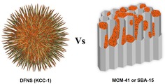
Advantages of using DFNS over MCM‐41 or SBA‐15 as a support. Orange dots represent active sites. (The fibers of DFNS are not as sharp and pointed as is shown in this cartoon, and they more so resemble the wrinkled petals of a flower.) Adopted with permission from Ref. 77. Copyright 2016 American Chemical Society.
DFNS, owing to its unique properties, has become a family of dendritic fibrous nanosilica spheres with a wide range of applications. It seems to have excellent potential as an alternative to popular silica materials such as MCM‐41, SBA‐15, Stöber silica, and mesoporous silica nanoparticles (MSNs) (Table 1, Figure 2). Although the surface area of DFNS is lower than that of either MCM‐41 or SBA‐15, accessibility of the surface area of DFNS is dramatically better than that of conventional silica, which allows increased loading of active sites and better diffusion of the reactants than that observed for MCM‐41 and SBA‐15 (Figure 1). DFNS also has a very unique pore‐size distribution (distance between fibers or channel size), which gradually increases from 3 to approximately 25 nm, unlike the narrow pore‐size distribution observed in conventional porous materials (Figure 2).
Figure 2.
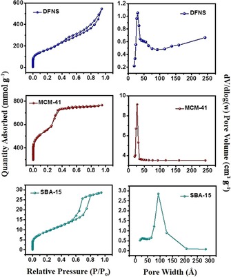
N2 sorption isotherms (left) and pore‐size distributions (right) of DFNS, MCM‐41, and SBA‐15.
Herein, we review the synthesis and mechanism of formation of DFNS, followed by its application in catalysis, photocatalysis, CO2 mitigation, biomedical technology, drug delivery, sensors, and supercapacitors. If possible, a comparison is made with conventional mesoporous materials, such as MCM‐41, SBA‐15, Stöber silica, and MSNs.
2. Synthesis and Mechanism of Formation of Dendritic Fibrous Nanosilica
In our original work, the synthesis of DFNS was achieved by a microwave‐assisted templated solvothermal protocol.17, 19 We used cetylpyridinium bromide (CPB) or cetyltrimethylammonium bromide (CTAB) as the template (surfactant), 1‐pentanol was used as a co‐surfactant, tetraethyl orthosilicate (TEOS) acted as the Si source, urea served as the hydrolyzing agent (catalyst), and a mixture of cyclohexane and water was used as the reaction solvent. The synthesis involved the stepwise addition and systematic mixing of these chemicals, followed by microwave‐assisted heating in a closed vessel at 120 °C for various reaction times. After washing and calcination, silica nanospheres (250 to 450 nm in size) were obtained with dendritic fibrous morphologies (Figure 3).
Figure 3.
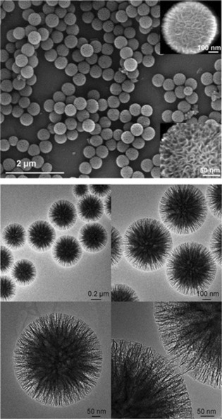
Top) Scanning electron microscopy (SEM) images and bottom) high‐resolution transmission electron microscopy images of fibrous silica nanospheres (DFNS).17
Close inspection of these images indicated that each sphere of DFNS was made up of dendritic fibers radially arranged and wrinkled with each other. Note that these fibers were not sharp hairy fibers but rather that they resembled the petals of a flower. Notably, the DFNS material was found to have a high surface area and pore volume. DFNS also inherently possesses excellent physicochemical properties, such as thermal stability up to 800 °C, mechanical stability up to 100 MPa, and hydrothermal stability. In our work,17 we also showed the possibility to control the sphere size, as well as the fiber density, simply by tuning the amount of urea and the reaction time.
After our discovery of DFNS,17 several reports appeared in the literature for the synthesis of DFNS with controllable sizes and textural properties by modifying the various reaction parameters (Table 2).
Table 2.
Summary of various synthesis conditions for DFNS.[a]
| Entry | Si precursor | Surfactant | Co‐surfactant | Base | Solvent | Reaction conditions | Ref. |
|---|---|---|---|---|---|---|---|
| 1 | TEOS | CTAB or CPB | 1‐pentanol | urea | water/cyclohexane | 120 °C, 4 h | 17, 19 |
| 2 | TEOS | CPB | propan‐2‐ol or n‐butanol | urea | water/cyclohexane | 70 °C, 16‐20 h | 20, 21 |
| 3 | TEOS | CTAB | n‐butanol | urea | water/toluene | 120 °C, 4 h | 22 |
| 4 | TEOS | CTAT | none | organic amines | water | 80 °C, 2 h | 23 |
| 5 | TEOS | CTAT | [BMIM]OTf | triethanolamine | water | 80 °C, 3 h | 24 |
| 6 | TEOS | CPB | 1‐pentanol | urea | water/cyclohexane | 120 °C, 20 h | 25 |
| 7 | TEOS | CTAC | none | triethanolamine | water/1‐octadecene | 60 °C, 12 h | 26 |
| 8 | TEOS | CTAB | ethanol | aqueous NH3 | water/ethyl ether | 20 °C, 4 h | 27 |
| 9 | TMOS | CTAB | none | triethanolamine | water | 80 °C, 12 h | 28 |
| 10 | TEOS | CTAB | ethanol | lysine, AIBA | water/octane and styrene | 70 °C, 20 h | 29 |
[a] TEOS: tetraethoxysilane, TMOS: tetramethoxysilane, CTAB: cetyltrimethylammonium bromide, CPB: cetylpyridinium bromide, CTAT: cetyltrimethylammonium tosylate, [BMIM]OTf: 1‐butyl‐3‐methylimidazolium trifluoromethanesulfonate, CTAC: cetyltrimethylammonium chloride, AIBA: 2,2′‐azobis(2‐methylpropionamidine) dihydrochloride.
The mechanism of formation of DFNS seems to be very complex, and although we did not study the mechanism of formation of DFNS in our original study,17 we did propose a mechanism on the basis of experimental observations and literature reports. The mechanism was thought to include the formation of reverse micelles of surfactant (template) molecules, followed by the assembly of hydrolyzed TEOS molecules (negatively charges silicates) within the space available in the template molecules. Finally, condensation of these silicates leads to the formation of silica, which grow in the radial direction to form spheres. However, this proposed mechanism does not answer some key questions, such as the disparity between the micelle size and the DFNS particle size, variation in the sphere size, and the dendritic nature of the silica fibers. Hence, this initially proposed mechanism does not stand valid today.
Nearly two years after of our initial DFNS report,17 Moon and Lee conducted an exceptionally detailed mechanistic study by using a bicontinuous microemulsion model (Winsor systems) to explain the mechanism of formation of DFNS, which they renamed wrinkled silica nanoparticles (WSNs).20 They proposed the formation of DFNS by using the Winsor III system, which was formed with a bicontinuous microemulsion phase consisting of the surfactant along with water and oil in the middle layer, and the excess amounts of water and oil were separated into the bottom and top layers.20 They investigated the wrinkled structure of the silica nanospheres generated under various reaction conditions by slightly modifying our original synthetic procedure:17 they replaced pentanol with propan‐2‐ol and replaced microwave heating with conventional heating at 70 °C for 16 h. They monitored the evolution of nanospheres at different time intervals. They observed an increase in the size of the particles with time but no change in the interwrinkle distances (the distance between two fibers). On the basis of these results, they proposed the bicontinuous template model (Winsor III) for the mechanism of formation. To study their hypothesis, they separated the middle bicontinuous microemulsion layer and the lower water layer (in a 1:1 volume ratio of cyclohexane/water), and silica was grown in each layer separately. They observed mesoporous silica nanoparticle formation in the water layer, whereas the formation of DFNS was observed in the microemulsion layer. This implied that bicontinuous microemulsion in a Winsor III system was the correct model.
Although wrinkled silica nanospheres were formed in the microemulsion layer, they were aggregated, unlike those in the stirred microemulsion system (Figure 4 e f). However, upon dilution of this separated microemulsion layer with water or cyclohexane, the layer dispersed quickly in water but remained as droplets in cyclohexane, which indicated that it was an oil‐in‐water‐type macroemulsion system, within which the bicontinuous microemulsion was distributed (Figure 4, top panel). They proposed that the hydrolysis–condensation of TEOS occurred in these bicontinuous microemulsion droplets within the macroemulsion system to yield monodisperse DFNS in contrast to the aggregated material in the separated creamed microemulsion layer. They also showed that by simply changing the ratio of cyclohexane to water, different microemulsion systems could be generated, and hence, silica nanospheres with different morphologies (dense mesoporous, expanded mesoporous, and wrinkled/fibrous structures) could be synthesized.20 They were also able to control the interwrinkle distance by changing the alcohol used in the synthesis of DFNS. The presence of small pores (2–4 nm) was due to micelle formation through the emulsion rupture–inversion process. This study provided remarkable insight into the mechanism of formation of DFNS.
Figure 4.
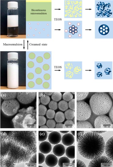
Top) Images and schematic of separated phases in the Winsor III system. Bottom) SEM/TEM images of silica nanoparticles from a, d) the upper microemulsion layer, b, e) the lower aqueous layer, and c, f) the macroemulsion system. Reprinted with permission from Ref. 20. Copyright 2012 American Chemical Society.
Moon and Lee then further tuned the DFNS synthesis on the basis of the phase behavior of the pseudoternary system by changing the water/surfactant/cyclohexane ratio.21 Here, water was a 0.4 m aqueous urea solution, and the surfactant was a CTAB/n‐butanol (1:1 w/w) mixture. Upon changing these ratios, they obtained DFNS with various amounts of wrinkling and varied pore sizes (Figure 5). They were also able to control the particle size of the nanospheres by further exploring our urea‐based synthetic approach.17
Figure 5.
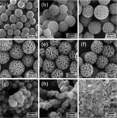
SEM images of silica nanomaterials synthesized by changing the water/surfactant/cyclohexane ratio. Reprinted with permission from Ref. 21. Copyright 2014 American Chemical Society.
Recently, Febriyanti et al. also studied the mechanism of formation of DFNS22 by using gray value intensity patterns [generated from the transmission electron microscopy (TEM) images of DFNS], the critical micelle concentration (found by specific conductance measurements), and Raman spectroscopy. They observed different gray value patterns (U‐ and W‐shaped plots) for different silica morphologies. The DFNS gray value pattern was U shaped and was similar to that of core–shell silica nanomaterials. However, it had additional fine features in the center region, which were generally due to wrinkles, sheets, and lamellae, and thus, they found the DFNS morphology to consist of bicontinuous concentric lamellae. A Tyndall experiment was performed to infer that the DFNS colloidal mixture was a macroemulsion. In a conductivity measurement experiment, they observed an increase in the electrical conductivity upon increasing the CTAB concentration, and this was due to the formation of reverse micelles. Moon and Lee also observed the formation of reverse micelles,20, 21 although these micelles were attributed to small pore formation within each fiber of DFNS. Febriyanti et al. further studied the emulsion by using Raman spectroscopy to investigate the nature of the water molecules and their hydrogen bonding relative to that in pure water. They found that the emulsion had more confined water molecules, possibly confined in the center of the reverse micelles, which acted as a template for DFNS formation (Figure 6).22
Figure 6.
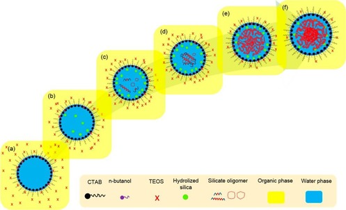
Schematic of the mechanism of formation of DFNS: a) diffusion of TEOS into a phase boundary, b) hydrolysis of TEOS, c) condensation of hydrolyzed TEOS, d) silicate oligomer formation, e) formation of bicontinuous structured silica, and f) silica with its final bicontinuous concentric morphology. Reprinted with permission from Ref. 22. Copyright 2016 American Chemical Society.
According to the authors, as a result of hydrophobic–hydrophobic interactions between TEOS and the tail of CTAB as well as the concentration gradient of TEOS inside and outside the reverse micelles (creating a high chemical potential), the TEOS molecules (present in the cyclohexane phase) reach the phase boundary of the reverse micelles.22 Hydrolysis of TEOS occurs at this phase boundary through interaction with water (and possibly decomposed urea catalysts), and hydrolyzed TEOS, in addition to the ethanol byproduct, penetrate inside the reverse micelle, as they are more soluble in the water phase. Further hydrolysis and condensation reactions occur to yield linear and branched siloxanes, and this causes the wrinkled nature of the silica fibers. Overall, this is an excellent study, although their proposed mechanism does not explain the formation of DFNS with various sizes or the dendritic nature of the fibers.
Using an organic amine (instead of urea) and cetyltrimethylamonium (CTA+) tosylate or bromide as templates, Zhang et al. synthesized 50 to 200 nm sized DFNS‐like materials.23 Smaller particles less than 50 nm in size were also prepared by simply using an additional nonionic surfactant, pluronic F127, which inhibited the growth of the silica particles.24 They also proposed a formation mechanism on the basis of self‐assembly and ion competition at the electrical shell of the micelles (Figure 7). Kinetically driven growth by the percolation of TEOS in the aggregated micelles, that is, the self‐assembly of micelles with hydrolyzed TEOS, could be the reason for the dendritic fibrous morphology.
Figure 7.
Proposed mechanism for the synthesis of dendritic silica nanospheres. TEAH3=triethanolamine. Reprinted with permission from Ref. 24. Copyright 2014 American Chemical Society.
Yang et al. investigated another protocol for the synthesis of DFNS by changing the reaction temperature, solvent ratio, and template concentration.25 They claimed that a high concentration of cyclohexane was crucial to form the fibrous morphology, which collapsed if a smaller amount of cyclohexane was used. However, the optimal solvent ratio of water/cyclohexane was 1:1 by volume, which was exactly the same as that in our initial report.17 Shen et al.26 also used our protocol for the synthesis of DFNS by using ethanolamine. They performed an extensive study and gained excellent understanding of the synthesis process, which helped them to tune the size and morphology of DFNS further by simply changing the base and solvent.26
A less energy‐demanding protocol to synthesize DFNS at 20 °C was brilliantly developed by Du et al.27 They replaced urea with ammonium hydroxide, cyclohexane with ethyl ether, and pentanol with ethanol. Notably, they were able to produce amine‐functionalized DFNS in one step at room temperature with good control over the size and morphology of the material. They observed that the volume ratio of ethanol to ethyl ether affected the morphology of the materials. Interestingly, they were able to tune the particle size by controlling the stirring speed of the reaction mixture and the reaction temperature (Figure 8). Additionally, they explained that at a higher stirring rate, the size of the quasiemulsion (as it was not stable) droplets decreased with the formation of a large number of particles, and hence, a greater number of smaller particles was formed.
Figure 8.
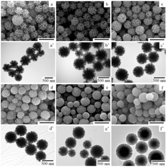
a–f) SEM and a′–f′) TEM images of amine‐functionalized nanosilica synthesized in an ethanol/ethyl ether (10:20 mL) emulsion system at reaction temperatures of a, a′) 10, b, b′) 15, c, c′) 20, d, d′) 25, e, e′) 30, and f, f′) 35 °C. Scale bars in the SEM images are 1 μm. Reprinted with permission from Ref. 27. Copyright 2015 Royal Society of Chemistry.
Yamada et al. then developed a swelling strategy to synthesize the DFNS family of silica nanospheres by modifying the standard DFNS protocol by replacing urea with triethanolamine.28 They used various trialkylbenzenes (TABs) as swelling agents or pore expanders, which allowed the hydrophobicity of the reaction medium to be tuned; this affected the hydrolysis rate of the silane precursors and thus the nucleation‐growth step. 1,3,5‐Triisopropylbenzene (TIPB) and 1,3,5‐trimethylbenzene (TMB) as TABs and tetrapropoxysilane (TPOS) and tetramethoxysilane (TMOS) as Si precursors were used to control the pore size and particle size of these silica nanospheres. The combination of TIPB and TPOS allowed tuning of the pore size from 4 to 8 nm and the particle size from 50 to 380 nm (Figure 9). The change in pore size was explained on the basis of the incorporation of TIPB inside the micelles (swelling), and the change in particle size was explained on the basis of a decrease in the rate of hydrolysis of the Si precursors, which accelerated the growth processes over nucleation.
Figure 9.
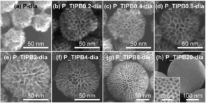
SEM images of silica nanospheres prepared by using TIPB and TPOS at various molar ratios (x), denoted P_TIPBx‐dia, for which x=a) 0, b) 0.2, c) 0.4, d) 0.8, e) 2, f) 4, g) 8, and h) 20. Reprinted with permission from Ref. 28. Copyright 2014 Royal Society of Chemistry.
Unlike TIPB, TMB was not effective in controlling the pore size. The authors systematically explained why TMB did not alter the pore size even though TIPB did (Figure 10). As TMB is a planer molecule, it can disperse between the space of two adjacent surfactant molecules in the micelles (Figure 10 b) without causing the micelles to swell (hence, no enlargement of the pores). On the other hand, TIPB is a larger molecule, and this makes it difficult to disperse between surfactant molecules (e.g., TMB), and hence, it goes into the hydrophobic center of the micelles (Figure 10 c); this causes swelling of the micelles, and hence, the pore diameter is increased.
Figure 10.
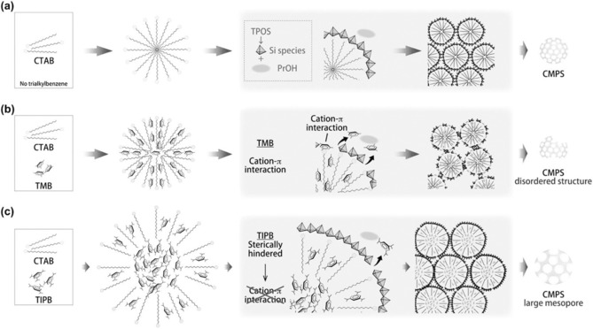
Possible structures of the micelles and the formation of various silica nanospheres: a) without TAB, b) with TMB, and c) with TIPB. CMPS=colloidal mesoporous silica nanoparticles. Reprinted with permission from Ref. 28. Copyright 2014 Royal Society of Chemistry.
Gustafsson et al. used various template molecules to prepare nanosilica materials with very small sizes (≈40 nm).29, 30 They used lysine (instead of urea) in a mixed solvent system of water/octane/styrene. It was found that cationic surfactants, as well as cationic gemini surfactants with short or long spacers between their polar heads, yielded silica nanospheres with particle sizes of 46 to 91 nm.
They also proposed a formation mechanism for DFNS (Figure 11).29 They suggest that DFNS formation occurs inside the droplets of a water‐in‐oil microemulsion, and these droplets are stabilized by surfactants and are present within the superfluous oil phase. In these water‐in‐oil droplets, TEOS is present in the oil phase, and upon exposure to water (at the oil–water interface) it hydrolyzes and condenses to form a three‐dimensional silica network. This leads to the gradual transition of the water‐in‐oil microemulsion into a bicontinuous microemulsion, and this internal change in the droplet yields the wrinkled fibers of the silica nanospheres.
Figure 11.
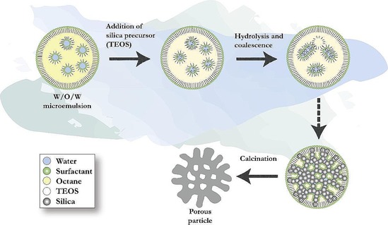
Proposed mechanism for the formation of dendritic silica nanoparticles. Reprinted with permission from Ref. 29. Copyright 2016 Elsevier B.V.
After our discovery of DFNS, several reputed groups worldwide reported modified processes to synthesize DFNS, as discussed above. Over a similar time period, we also developed a simple protocol for the synthesis of monodisperse DFNS with controllable sizes, fiber densities, and textural properties.19 We were able to achieve fiber density control. The particle size, fiber density, surface area, and pore volume of DFNS were effectively controlled and tuned by changing various reaction parameters, such as the concentrations of urea, CTAB, and 1‐pentanol; the reaction time; the temperature; the solvent ratio; and even the outside stirring time. After this systematic study, we were able to tune the particle size, and now, one can synthesize DFNS with a particle size as small as 170 nm to as large as 1120 nm. Interestingly, we were also able to double the surface area of DFNS to 1244 m2 g−1 and to achieve a pore volume of 2.18 cm3 g−1, which are the highest values reported to date for DFNS.19
3. Catalysis using DFNS
3.1. DFNS‐supported metal nanoparticles
Metal nanoparticle (NP)‐based catalysts are key in most chemical transformations, and supporting them on solids makes them stable and reusable.5 Their activity generally depends on the surface area of the metal, which is dependent on its size and its accessibility. More often than not, the accessibility of these supported metal active sites is always a serious issue. These sites are less accessible owing to the porous nature of most supports, which causes a diffusion barrier for reactants and products, and this greatly hampers the accessibility of the active sites and thus the catalytic performance. Additionally, small‐sized active sites are also prone to agglomeration and sintering during reactions, which thus deactivates the catalyst. Therefore, a novel approach to design active and stable supported metal nanocatalysts was needed, and fibrous nanosilica helped in this regard.
After the discovery of DFNS in 2010,17 the first application we considered was the exploration of its open and fibrous morphology for supporting metal nanoparticles and organometallic complexes to design nanocatalysts with more accessible active sites. In this regard, the very first application of DFNS that was explored was a ruthenium (Ru) catalyst (DFNS/Ru, Figure 12) for the hydrogenolysis of alkanes.31 The DFNS/Ru nanocatalyst was prepared by functionalizing the DFNS surface with 3‐aminopropyltriethoxysilane (APTS), which was then loaded with a ruthenium chloride salt (Figure 12). Reduction using hydrogen gas yielded DFNS/Ru with small (1–4 nm) Ru NPs uniformly dispersed over the fibers of DFNS. Solid‐state cross‐polarization magic‐angle spinning nuclear magnetic resonance (CP‐MAS NMR) spectroscopy and thermogravimetric analysis (TGA) indicated that a 10 wt % loading of covalently attached APTS helped in the formation of monodispersed Ru NPs on DFNS fibers (Figure 12).
Figure 12.
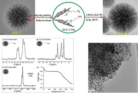
Design and synthesis of the DFNS/Ru nanocatalyst. Adapted with permission from Ref. 31. Copyright 2012 American Chemical Society.
DFNS/Ru was then explored in the propane hydrogenolysis reaction (Figure 13). The reaction progressed efficiently with approximately 84 % conversion and 73 % selectivity toward methane and 27 % toward ethane. Notably, the cumulative turnover number (TON) was greater than 11 000, and even after 7 days, no change in the conversion or selectivity was observed; moreover, the recycled catalyst worked as efficiently as the fresh catalyst. Relative to the SBA‐15/Ru and MCM‐41/Ru catalysts, DFNS/Ru was superior in terms of TON (Table 3). The effectiveness of DFNS/Ru was due its fibrous morphology, as this increased the accessibility of the Ru sites, which are restricted in SBA‐15 and MCM‐41 due to the tubular pores having only two openings. The enhancement was also attributed to the smaller size and the presence of a fair amount of hexagonal nanoparticles of Ru, which had atoms (active sites) with low coordination numbers (more dangling bonds) and, hence, high surface energy. In the case of KCC‐/Ru, the fibers of DFNS (within which the Ru NPs were dispersed) restricted their agglomeration/sintering and, hence, particle growth, which helped to maintain catalyst activity.
Figure 13.
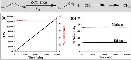
a) Conversion TON and b) selectivity for propane hydrogenolysis catalyzed by DFNS/Ru in a continuous‐flow reactor at 175 °C and 0.1 MPa pressure by using hydrogen.31
Table 3.
Comparison of DFNS/Ru with SBA‐15/Ru and MCM‐41/Ru for propane hydrogenolysis reaction.[a]
| Catalyst | T [°C] | Conversion [%] | C2H6 selectivity [%] | TON after 7 days |
|---|---|---|---|---|
| KCC‐1/Ru | 175 | 84 | 27 | 11010 |
| SBA‐15/Ru | 175 | 77 | 27 | 7210 |
| MCM‐41/Ru | 175 | 25 | 14 | 3927 |
Like DFNS/Ru, we also prepared a supported palladium (Pd) catalyst (DFNS/Pd) by using a similar strategy.32 After APTS functionalization of DFNS, palladium chloride was loaded; this was followed by reduction of PdII to Pd0 by the hydrogen reduction method, which yielded DFNS/Pd that had fibers of DFNS that were fully loaded with well‐dispersed Pd NPs 1–5 nm in size. This catalyst showed excellent activity with 77 to 95 % conversion and stability (over at least seven cycles) in Suzuki carbon–carbon (C−C) coupling reactions by using both bromo‐ and chloroaromatics (Figure 14). However, the catalysts showed some deactivation after seven cycles, which indicated that some leaching of Pd occurred, and hence, a more leachproof catalyst was needed.
Figure 14.
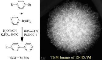
DFNS‐NH2/Pd‐catalyzed Suzuki coupling reactions of bromoaromatics.32
The DFNS/Pd nanocatalyst was then further explored by D'Elia et al. for the transfer hydrogenation of alkenes.33 They obtained similar average sizes of the Pd NPs on all three supports; however, DFNS showed a better dispersion of metal NPs than the SBA‐15 and MCM‐41 supports. Pd/KCC‐1‐NH2 showed a conversion that was 1.6 times higher than that of Pd/MCM‐41‐NH2 and 2.6 times higher than that of Pd/SBA‐15‐NH2.
The DFNS/Pd catalyst was also used by Ma et al. in the reduction of 4‐nitrophenol and in the hydrodechlorination of 4‐chlorophenol.34 They also observed good catalytic activity under mild reaction conditions in addition to stability (recyclability) of the catalysts (Figure 15). DFNS/Pd was also explored for the aqueous‐phase hydrodechlorination and then the hydrogenation of chlorophenols to cyclohexanone.35 The catalysts worked well for this process and followed a pseudo‐first‐order rate equation with a rate constant per unit mass (k 1) of 13.2 min−1 g−1. Zhao's group36 explored DFNS/Pd for the Suzuki coupling reaction, although the activity was limited to iodo and bromoaromatics.
Figure 15.
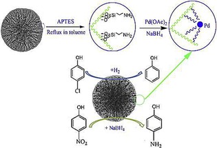
Synthesis and application of the DFNS/Pd nanocatalyst. APTES=(3‐aminopropyl)triethoxysilane. Reprinted with permission from Ref. 34. Copyright 2015 Elsevier B.V.
To improve the stability of DFNS/Pd, our group replaced APTS with polyethylenimine (PEI), which led to leachproof and monodisperse DFNS/X (X=Rh, Ru, Pd) catalysts.37 DFNS was first functionalized with (3‐glycidyloxypropyl)trimethoxysilane (GTMS), which upon reaction with PEI yielded PEI‐functionalized DFNS (Figure 16). These were then used as pseudoligands to produce and stabilize monodisperse metal nanoparticles, wherein the metal (i.e., Rh, Ru, and Pd) salts bound with the amines of PEI; reduction with NaBH4 produced metal(0) nanoparticles that were highly dispersed on the fibers of DFNS (Figure 16). These nanocatalysts showed good catalytic activity in the hydrogenation of phenylacetylene and styrene, and this was attributed to the smaller size of the metal NPs as well as their high accessibility owing to the fibrous nature of the support. The combination of PEI and DFNS also restricted metal leaching, which in turn increased the stability of the catalysts. However, some passivation of the active sites by PEI was observed.
Figure 16.
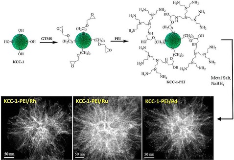
Design of DFNS‐supported metal (Rh, Ru, and Pd) nanoparticles by using PEI functionalization. Reprinted with permission from Ref. 37. Copyright 2015 American Chemical Society.
DFNS‐PEI/Pd was further explored by Bhanage and co‐workers in the carbonylation Suzuki–Miyaura cross‐coupling reaction.38 DFNS‐PEI/Pd catalysts with six different Pd loadings (i.e., 10, 2, 1, 0.5, 0.3, and 0.1 wt %) were prepared and evaluated for catalysis (Figure 17). The catalyst with 0.1 wt % Pd showed a 28‐fold higher TON and a 51‐fold higher turnover frequency (TOF) than the best supported Pd catalyst in the carbonylation cross‐coupling of 4‐iodoanisole and phenylboronic acid. The catalyst was recycled up to 10 times with marginal loss in activity after the 8th cycle.
Figure 17.

DFNS‐PEI/Pd‐catalyzed carbonylation Suzuki–Miyaura cross‐coupling reaction. Reprinted with permission from Ref. 38. Copyright 2016 Royal Society of Chemistry.
Interestingly, DFNS‐PEI/Pd could also catalyze the reverse carbonylation reaction, that is, the decarbonylation reaction by simply changing the reaction conditions. Kundu et al. used DFNS‐PEI/Pd in the decarbonylation of a variety of aromatic, heteroaromatic, and alkenyl aldehydes.39 Complete conversion of the aldehyde functionalities into their deformylated products was achieved with very pure isolated products without using any additives (e.g., oxidants, bases, or CO scavengers). This catalyst also showed excellent stability (recyclability), and even after eight cycles, the catalyst had the same activity (Figure 18). Thus, DFNS‐PEI/Pd could catalyze the carbonylation reaction as well as the decarbonylation reaction by simply changing the reaction conditions.
Figure 18.
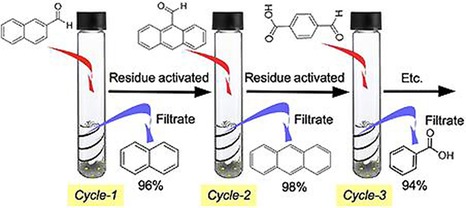
Recyclability of DFNS‐PEI/Pd in the decarbonylation reaction. Reprinted with permission from Ref. 39. Copyright 2016 Wiley‐VCH.
Similar to the PEI approach,37 Sadeghzadeh developed a protocol for using multicarboxylic hyperbranched polyglycerol groups (HPGs) as robust anchors for various metal nanoparticles (e.g., Au, Pd, and Cu).40 The HPGs were directly grafted onto the DFNS fibers by the surface‐initiated ring‐opening polymerization of glycidol, and then the metal salts were loaded, which was followed by reduction with NaBH4. These catalysts were efficient in the reaction of CO2 with 2‐aminobenzonitriles to produce quinazoline‐2,4(1H,3H)‐diones in good yields.
Instead of confining or supporting these metal nanoparticles inside the DFNS spheres, Wang et al. attempted to coat Pd NPs by DFNS by using the microemulsion method to obtain core–shell‐type structures with Pd as the core and silica as the shell.41 They compared the activity of this catalyst in the oxidation of carbon monoxide (CO) with that of other catalysts prepared in the conventional way of silica coating (e.g., Stöber's method, impregnation, and reverse‐micelle method). Using the microemulsion method, they were able to obtain a Pd‐core DFNS‐shell catalyst with an average DFNS particle size of 350 nm and a Pd size of 14 nm. However, the catalytic activity of this catalyst was poor relative to that of the catalyst prepared by the reverse‐micelle method (Figure 19), the overall particle size of which was 30 nm with a Pd size of 1.1 nm. They found this catalyst to be sinterproof, even at high temperatures. However, this comparison may not be accurate, as there was a huge difference in the size of the Pd NPs as well as the overall size of the catalyst, which was 30 nm compared with 350 nm. Hence, a dependence on morphology cannot be concluded from this study.
Figure 19.
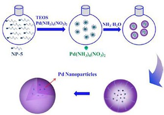
Schematic illustration of the synthesis of silica‐coated Pd by using the reverse‐micelle method. Reprinted with permission from Ref. 41. Copyright 2016 Royal Society of Chemistry.
Using APTS‐functionalized DFNS, Dong et al. prepared a silver (Ag) catalyst (DFNS/Ag) and evaluated it in the reduction of 4‐nitrophenol and 2‐nitroaniline (Figure 20).42 They were able to perform this reaction at room temperature by using water as the solvent, which make this process green and energy efficient. The catalyst was stable for up to 10 cycles, which they attributed to the fibrous morphology and the APTS functionalization of DFNS. After 2 years, the group of Yan et al. prepared the catalyst (DFNS/Ag) and renamed it as dendritic‐mSiO2‐NH2‐Ag. They evaluated it for the same reaction, the reduction of 4‐nitrophenol and 2‐nitroaniline, and found similar catalytic performance.43
Figure 20.
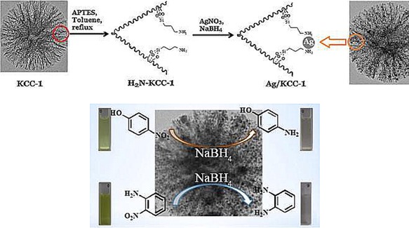
Top) DFNS/Ag catalyst design and bottom) catalytic reduction of 4‐nitrophenol and 2‐nitroaniline by using the DFNS/Ag catalyst. Reprinted with permission from Ref. 42. Copyright 2014 Elsevier B.V.
Ouyang et al. prepared DFNS/Ag catalysts by using the conventional impregnation method without APTS functionalization and evaluated them for the gas‐phase hydrogenation of dimethyl oxalate (DMO) to methyl glycolate (MG).44 They compared DFNS/Ag with MCM‐41/Ag and SBA‐15/Ag to study the role of morphology of the support. They observed that different silica supports resulted in different dispersions and accessibilities of the Ag sites. They screened these three catalysts for the hydrogenation of DMO with different liquid hourly space velocity values. The open fibrous structure of DFNS enhanced the diffusion of DMO and MG, which significantly improved the TOF value relative to that obtained for the MCM‐41‐ and SBA‐15‐based catalysts (Figure 21).
Figure 21.

Dimethyl oxalate (DMO) to methyl glycolate (MG) conversion by using Ag/KCC‐1 and Ag/MCM‐41. Reprinted with permission from Ref. 44. Copyright 2016 Royal Society of Chemistry.
D'Elia and co‐workers slightly modified the protocol for the synthesis of DFNS/Au by replacing the reducing agent (i.e., NaBH4) by CO and citrate.45 On the basis of the method of catalyst preparation and the reducing agent used, they obtained DFNS loaded with Au NPs of varying sizes and dispersions. These catalysts were then evaluated for the oxidation of CO, and the results showed that the activity of DFNS/Au was similar to that of other reported silica‐based Au catalyst.
3.2. DFNS‐supported pseudo‐single atoms of metals
Nanocatalysis is no longer just a field of academic curiosity but is now an emerging field for industries to develop green and economical processes.5 Hutching's recent report on nanogold catalysts is a good example.46 However, next‐generation nanogold catalysts with very high turnover numbers and stability are needed to take this field to the next level. For this, new catalyst design approaches, such as Zhang's unique single‐atom catalysts,47 need to be developed. In this regard, we used DFNS to prepare active and stable pseudo‐single‐atom catalysts of Pt and Au.48, 49
At the time, most reported single‐atom catalysts were based on the utilization of active supports that exhibited strong metal–support interactions.47 We recently used DFNS to synthesize sub‐nanometer‐sized platinum nanoparticles and pseudo‐single atoms of Pt. This size tuning from the nanometer scale to the sub‐nanometer scale to pseudo‐single atoms was used to tune the chemoselectivity of the hydrogenation reaction of 3‐nitrostyrene (Figure 22).48 DFNS‐PEI/Pt (1 %) with ultrasmall and pseudo‐single atoms as active sites showed selectivity toward 3‐vinylaniline, whereas 10 and 5 % Pt loaded on DFNS‐PEI (with 2.2 and 1.8 nm active‐site average sizes, respectively) showed selectivity toward 3‐ethylaniline. DFNS‐PEI/Pt (1 %) displayed a TON of 1230 compared to a TON of 178 displayed by Pt/SiO2 for the hydrogenation of 3‐nitrostyrene with improved selectivity (70 % for 3‐vinylaniline compared to 40 % by Pt/SiO2).48 Notably, catalysts with sub‐nanometer Pt or pseudo‐single atoms of Pt had excellent selectivity of 60–70 %, which decreased drastically with an increase in the particle size.
Figure 22.
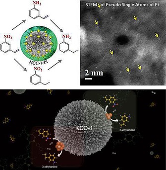
Engineering the reaction selectivity by controlling the Pt particle size supported on DFNS. Adapted with permission from Ref. 48. Copyright 2016 Royal Society of Chemistry.
Nanogold catalysis has been a topic of considerable interest, and supported gold catalysts have dispelled the traditional belief about gold's unreactive behavior.46 Although these nanocatalytic transformations are very attractive, they are often limited by low turnover numbers in several cases. Atomically dispersed catalysts are the way forward in the field of Au nanocatalysis. Following our DFNS/Pt work, we also prepared ultrasmall/pseudo‐single‐atom gold catalysts supported on DFNS. Our approach involved grafting APTS onto the DFNS surface, which tethered with HAuCl4, and this was followed by NaBH4 reduction to afford DFNS‐supported Au nanoparticles.49
TEM analysis of the synthesized nanogold catalysts with different loadings (i.e., 10, 5, 1, 0.5, and 0.05 %), revealed the formation of ultrasmall Au NPs (Figure 23). The average particle size of the 10 % Au‐loaded sample was approximately 7.3 nm with a slightly broad particle‐size distribution. The average particle sizes of the 5, 1, and 0.5 % Au‐loaded on DFNS samples were approximately 2.7, 1.7, and 1.5 nm, respectively, with a very narrow particle distribution. Thus, DFNS appeared to be fully loaded and uniformly covered with monodisperse gold nanoparticles. Notably, at a 0.05 % loading, we also observed several pseudo‐single atoms.
Figure 23.
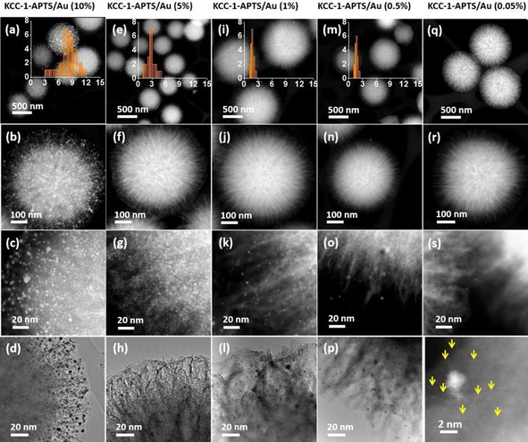
TEM images of DFNS‐APTES/Au with Au loadings of a–d) 10 %, e–h) 5 %, i– l) 1 %, m–p) 0.5 %, and q–t) 0.05 % . Reprinted with permission from Ref. 49. Copyright 2016 Royal Society of Chemistry.
We used the silane to silanol reaction as a test reaction to evaluate various DFNS/Au catalysts. We demonstrated that DFNS decorated with ultrasmall Au NPs and their pseudo‐single atoms was one of the best catalysts for the oxidation of silane, as it provided a very high TON. For example, DFNS‐APTS/Au (0.05 %) showed a TON of 591 000 for the oxidation of dimethylphenylsilane, whereas the highest reported TON without using any catalyst activation was 98 333 by using the Au/MnO2 catalyst.49 However, for an integrated view of various other key factors, such as the rate of the reaction, that is, the turnover frequency, the energy required for the reaction, the scale of the reaction, and the number of catalyst recycles, the figure of merit (FOM) was used [Eq. (1)]:
| (1) |
in which N is the number of cycles, S is the scale of the reaction, and ΔT is the deviation in the reaction temperature from ambient temperature (298 K). DFNS‐APTS/Au (0.05 %) was found to have a FOM of 633 mmol h−1 K−1 compared to a FOM of 247 for the Au/MnO2 catalyst (Figure 24).49 The presence of ultrasmall nanoparticles and pseudo‐single atoms of Au and the fibrous morphology of DFNS contributed to the superior performance of DFNS/Au, as did the presence of Auδ+ species. DFNS‐APTS/Au was also able to catalyze two other reactions, the alcoholysis of silane and the hydrosilylation of aldehydes, which thus makes it a versatile nanocatalyst.49
Figure 24.
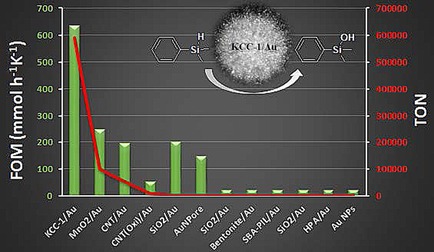
Comparison of the DFNS‐APTS/Au (0.05 %) catalyst with various other reported catalysts for the oxidation of dimethylphenylsilane. Single‐digit FOM values were scaled to 20 for visualization in the figure. Reprinted with permission from Ref. 49. Copyright 2017 Royal Society of Chemistry.
3.3. DFNS‐supported metals oxides and hydroxides
In addition to metals, metal oxides and metal hydroxides were also supported on DFNS to design novel nanocatalysts. Lee et al. prepared DFNS‐supported cobalt‐oxide catalysts for the Fischer–Tropsch (FT) reaction, which they renamed wrinkled silica nanoparticle (WSN)‐supported cobalt (Co) oxide (WSN‐CoO).50 Lee's group excellently used the fibrous nature of DFNS (or WSN) to stabilize cobalt oxide within these wrinkled fibers, which prevented sintering. To synthesize the catalyst, they used our APTS‐DFNS approach,32 for which APTS‐functionalized DFNS was treated with cobalt nitrate and then heated at 400 °C for 4 h to yield DFNS‐CoO (or WSN‐CoO), which was reduced to Co by the hydrogen reduction method (Figure 25). High‐resolution TEM studies showed that DFNS was fully loaded with cobalt‐oxide particles with an average size of 20 nm (Figure 26).
Figure 25.

a) Synthesis of WSN‐NH2 by APTS functionalization of WSNs, b) treatment with Co(NO3)2 ⋅6 H2O, and c) in situ reduction of WSN‐CoO. Reprinted with permission from Ref. 50. Copyright 2016 Korean Chemical Society and Wiley‐VCH.
Figure 26.
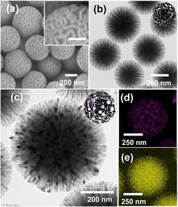
a) SEM and b) TEM images of WSNs. The inset scale bar is 100 nm. c) HRTEM image of WSN‐CoO. Bottom‐right panel) Energy‐dispersive X‐ray spectroscopy (EDS) elemental mapping of WSN‐CoO showing d) cobalt and e) silicon. Reprinted with permission from Ref. 50. Copyright 2016 Korean Chemical Society and Wiley‐VCH.
Notably, upon comparing DFNS/CoO (WSN‐CoO) with a conventional silica‐supported cobalt oxide (Co/SiO2) of similar loading, they observed that the initial activity of WSN‐CoO was lower than that of Co/SiO2, but in terms of stability, WSN‐CO remained nearly stable for 50 h, which confirmed the role of the DFNS fibers in stabilizing the Co active sites.50
Quan's group incorporated manganese (Mn) oxide in DFNS51 by using a one‐pot DFNS protocol by incorporating a Mn precursor (manganese nitrate) in addition to the silica precursor (TEOS) with different Mn/Si ratios. The catalyst was named MnOx‐Y/DFNS, in which MnOx represents the multivalent states of manganese oxide and Y indicates the Mn/Si molar ratio (Figure 27). Noncatalytic ozonation and catalytic ozonation by MnOx‐0.013/DFNS and MnOx‐0.013/MCM‐41 led to 4, 85, and 60 % reduction in the total organic content (TOC), respectively. In terms of Mn leaching, 0.05 and 1.2 mg L−1 leaching were detected for MnOx‐0.013/DFNS and MnOx‐0.013/MCM‐41, that is, 2.0 and 42.0 % of the total Mn present in the corresponding catalyst, respectively. These results clearly indicate the advantages of the fibrous DFNS support over MCM‐41 with respect to the activity as well as the stability (leaching).
Figure 27.
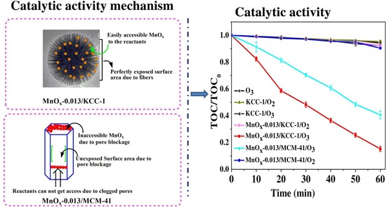
The MnOx‐Y/DFNS catalyst in the ozonation of oxalic acid. Reprinted with permission from Ref. 51. Copyright 2016 Elsevier B.V.
Yan et al. also prepared DFNS/Mn3O4 by using a two‐step process.52 First, they prepared DFNS and then loaded it with manganese acetate (of different amounts), which was followed by treatment with hydrazine hydrate for 24 h to yield DFNS/Mn3O4. The removal of methyl orange (MO) from waste water was systematically studied, and they concluded that these adsorption processes were controlled by intraparticle diffusion as well as external mass transfer and both seemed efficient owing to the fibrous DFNS support.
3.4. DFNS‐based zeolites
Excitingly, DFNS was converted into a zeolite‐based material. ZSM‐5 is an industrial zeolite used for its superior properties. However, the micropores of ZSM‐5 restrict access to the active sites and molecular diffusion, and hence, ZSM‐5 with a better pore structure was needed.53 Firmansyah et al. used the DFNS synthetic protocol to prepare fibrous ZSM‐5 by using zeolite crystal seeds and TEOS as precursors.53 After calcination, as‐prepared FZSM‐5 was exposed to twofold protonation (HFZSM‐5) and then Pt NP impregnation to yield Pt/HFZSM‐5. Pt/HFZSM‐5 was found to have the DFNS fibrous morphology with widely distributed Si and Al atoms and scarcely distributed Pt NPs (Figure 28). Pt/HFZSM‐5 showed 89.5 % total product yield in the hydrocracking of cumene and several other molecules compared to conventional Pt/HZSM‐5, which showed 65.8 % total product yield. Notably, Pt/HFZSM‐5 was stable and could maintain 88 % conversion, whereas the catalytic activity of Pt/HZSM‐5 was reduced to 15 % after 100 doses of cumene. The authors attributed this high activity to the fibrous morphology of FZSM‐5 as well as to the protonation ability and Pt NP sites.53
Figure 28.
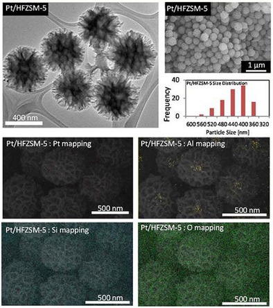
TEM, field‐emission scanning electron microscopy (FESEM), particle‐size distribution, and EDS elemental mapping of Pt/HFZSM‐5. Reprinted with permission from Ref. 53. Copyright 2016 Royal Society of Chemistry.
Then, they prepared fibrous ZSM‐5 (denoted FmZSM‐5) by using a modified DFNS protocol (Figure 29) for the CO methanation reaction and compared its performance to that of conventional recrystallized RmZSM‐5 (Figure 30).54 FmZSM‐5 was found to have superior CO conversion and CH4 formation rates of 0.0708 μmolCO m−2 s−1 and 0.0488 μmol m−2 s−1, respectively, which were twofold higher than the same values for conventional RmZSM‐5. Notably, FmZSM‐5 was stable for up to 50 h with no sign of deactivation.
Figure 29.
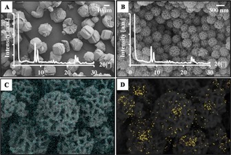
FESEM images and X‐ray diffraction patterns of a) RmZSM‐5 and b) FmZSM‐5 and EDS elemental mapping of c) Si and d) Al in FmZSM‐5. Reprinted with permission from Ref. 54. Copyright 2016 Elsevier B.V.
Figure 30.
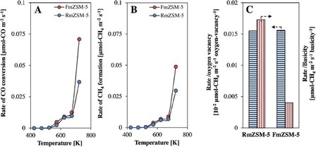
Rates of a) CO conversion and b) CH4 formation at a gas hourly space velocity of 13 500 mL g−1 h−1 and H2/CO=8:1 and c) the rate versus oxygen vacancy and basicity. Reprinted with permission from Ref. 54. Copyright 2016 Elsevier B.V.
Yi et al. developed an exceptionally efficient postsynthetic method to incorporate aluminum (Al) sites in the fibers of DFNS without even minute changes in its wrinkled fibrous morphology.55 They developed a new “pH‐assisted delay addition” two‐step protocol, for which the Al precursor, aluminum sulfate octadecahydrate, was added to preformed DFNS (obtained by using the standard hydrothermal process),17 which was then subjected to a second hydrothermal treatment. Notably, before adding the Al precursor, they observed that the pH of the mother liquor (initial pH≈9–10) need to be reduced to pH 5 by adding 2 m HCl to retain the fibrous wrinkled morphology of the DFNS/Al spheres, denoted ASN‐X, in which X indicates the Si/Al ratio. Interestingly, by simply replacing the 2 m HCl solution with a 2 m H3PO4 solution, they were able to incorporate phosphorus (P) in addition to Al in DFNS, denoted ASPN‐X. Both of these materials were dendritic fibrous spheres of 450 to 600 nm size with radially oriented pores and uniformly distributed elements of Si, Al, and P (Figure 31). The surface areas of the samples with different Si/Al ratios were approximately 475 to 515 m2 g−1 with a multimodal pore‐size (slit‐shaped) distribution.55
Figure 31.
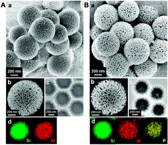
a, b) SEM images, c) TEM images, and d) EDS elemental mapping of the A) ASN‐40 and B) ASPN‐40 samples. Reprinted with permission from Ref. 55. Copyright 2014 Royal Society of Chemistry.
The catalytic performances of ASN‐40 and ASPN‐40 were evaluated and compared with those of HZSM‐5 and AlMCM‐41 by using the cracking of 1,3,5‐triisopropylbenzene and the hydrolysis of sucrose as test reactions (Figure 32). In the cracking reaction, HZSM‐1 showed poor activity, whereas AlMCM‐41, after initially showing moderate activity, was quickly deactivated. Notably, ASN‐40 (≈30 % conversion) and ASPN‐40 (60 % conversion) showed high activities (compared to ≈15 and ≈10 % conversions by AIMCM‐41 and ZHSM‐5, respectively) and long lifetimes (8–10 h compared to 4–5 h for the conventional catalysts),55 which possibly resulted from reduced coke formation owing to the fibrous morphology of the catalysts. These results clearly showed the potential of these DFNS‐based acid catalysts for industrial applications.
Figure 32.
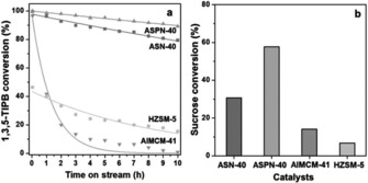
a) Cracking of 1,3,5‐triisopropylbenzene (1,3,5‐TIPB) and b) hydrolysis of sucrose by using ASN‐40, ASPN‐40, AlMCM‐41, and HZSM‐5. Each line in panel a indicates a fitted curve by the first‐order deactivation model. Reprinted with permission from Ref. 55. Copyright 2014 Royal Society of Chemistry.
Fenton catalysts based on DFNS were designed and synthesized by Lyu et al.56 The Fenton process is a powerful method to degrade pollutants in wastewater, although the stability of the catalysts has been an issue. The authors used the DFNS synthetic protocol to prepare dandelion‐like copper (Cu)‐Al‐silica nanospheres (DCASNs) by using copper nitrate, aluminum nitrate, and TEOS as the precursors, and this catalyst was used for the degradation of various pollutants at neutral pH. The reaction rate upon using the DCASNs catalyst was 5.2–13.4 times higher than that reported for Fenton catalysts such as Cu‐γ‐Al2O3 and Cu‐MCM‐41 (Figure 33). Figure 34 shows that the Cu sites are in the bulk of Cu‐γ‐Al2O3, and this reduces the accessibility of the pollutants to this active sites, and although Cu‐MCM‐41 has a very high surface area, it struggles with diffusion of the pollutants, which reduces its catalytic activity. However, in the DFNS‐based DCASNs, the accessibly of the active sites and the diffusion of the pollutants are improved (Figure 34 c), which make this catalyst the best performing in its class.
Figure 33.
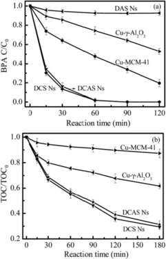
a) Degradation of 2,4‐dichlorophenoxyacetic acid (BPA) and b) total organic carbon (TOC) removal by using H2O2. Reprinted with permission from Ref. 56. Copyright 2016 Royal Society of Chemistry.
Figure 34.
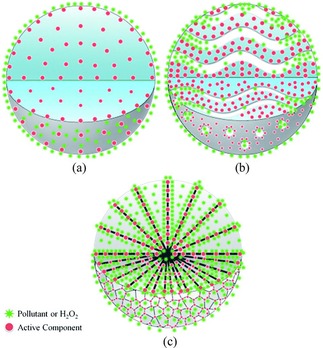
Schematic illustration of pollutants or H2O2 in contact with a) a catalyst with the active component in the bulk (such as γ‐Al2O3), b) a multiporous catalyst (such as MCM‐41), and c) DCASNs. Reprinted with permission from Ref. 56. Copyright 2016 Royal Society of Chemistry.
Wu's group prepared titanium silicalite‐1 (TS‐1) zeolites by coating TS‐1 with DFNS.57 Owing to the negatively charged TS‐1 surface, positively charged CTAB micelles were adsorbed on the surface and DFNS fibrous silica grew on the TS‐1 particle to produce a core–shell structure, named TS‐1@DFNS. The TS‐1 core was approximately 250–300 nm, with a fibrous shell of 80 nm. Rh(OH)3 was then supported on TS‐1@DFNS to produce a bifunctional nanocatalyst, Rh(OH)3/TS‐1@DFNS, for the one‐pot synthesis of amides by a tandem reaction involving the ammoximation and rearrangement of aldehydes, ammonia, and H2O2 (Figure 35). These two tandem steps occurred on Rh(OH)3/TS‐1@DFNS with good activity (93.5 % in terms of aldehyde conversion) and excellent stability (at least five cycle). Owing to confining and stabilizing effects, fibrous Rh(OH)3/TS‐1@DFNS showed negligible Rh leaching relative to conventional Rh(OH)3/TS‐1.58
Figure 35.
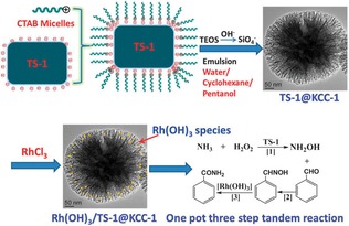
Schematic for the synthesis of Rh(OH)3/TS‐1@DFNS and its application in the one‐pot synthesis of amides. Reprinted with permission from Ref. 57. Copyright 2013 Royal Society of Chemistry.
DFNS/TS‐1 was also used in the development of pickering interfacial catalysts by the Wu and Pera‐Titus group.59 A pickering emulsion is an emulsion that is stabilized by solid particles, such as nanosilica, and one can perform catalysis in these emulsions, which is known as pickering interfacial catalysis (PIC). An amphiphilic zeolite/silica composite, named TS‐1@DFNS (TK), was synthesized by grafting octylsilane and hexadecylsilane (Figure 36). The catalysts were then evaluated in the hydroxylation of benzene by using hydrogen peroxide (H2O2) in PIC and phase‐boundary catalysis (PBC). PIC relies on the solid nanoparticles to act as emulsifiers as well as catalysts, whereas PBC relies on the solid nanoparticles lying at the boundary of the aqueous–organic phase (without emulsifying). Thus, ideally, pickering interfacial catalysts will have large interfacial surface areas, and this will increase the interaction of the catalysts with the reactants and, thus, expedite the catalytic process. TK showed a better TON than TS‐1 (Figure 37) as a result of its fibrous morphology and hydrophobic functionality on the surface, which helped the catalyst to disperse well (Figure 38).
Figure 36.
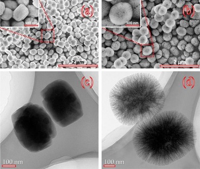
SEM and TEM images of a, c) TS‐1 and b, d) TK. Reprinted with permission from Ref. 59. Copyright 2015 American Chemical Society.
Figure 37.
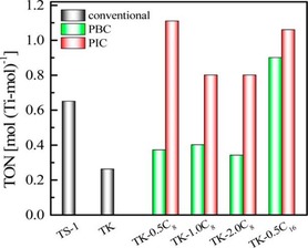
Benzene hydroxylation under PIC, PBC, and conventional conditions. Reprinted with permission from Ref. 59. Copyright 2015 American Chemical Society.
Figure 38.
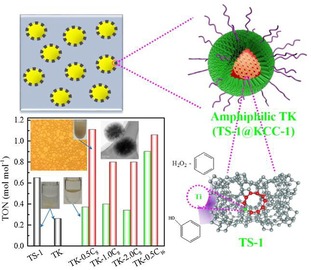
Schematic of the hydroxylation of benzene under pickering interfacial catalysis (PIC) by using TK. Reprinted with permission from Ref. 59. Copyright 2015 American Chemical Society.
3.5. DFNS‐based solid bases and acids
Solid bases, such as silica oxynitrides, are important catalysts for various processes in industry. The basicity of these nitrogen‐based hybrid materials is attributed to the various amine sites on their surface. High surface area silica materials, such as MCM‐41 and SBA‐15, were used to develop active solid bases by their nitridation with ammonia gas at high temperature.60, 61 Although both of these materials possess good basicity, their performance was limited because of restricted access of the amine sites inside the pores as well as their poor thermal stability during high‐temperature nitridation, which distorts their internal structures and further restricts accessibility of the active sites. We were able to overcome these issues by using DFNS as a support in oxynitride synthesis.62 DFNS‐oxynitrides (DFNS‐N) were prepared by an ammonia nitridation protocol at different temperatures (Figure 39), and then their base catalytic activities were compared with those of MCM‐41‐oxynitrides and SBA‐15‐oxynitrides by using the Knoevenagel condensation and transesterification reactions.
Figure 39.
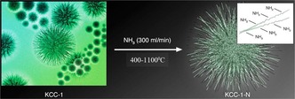
Nitridation of DFNS by using ammonia at different temperatures. Reprinted with permission from Ref. 62. Copyright 2013 American Chemical Society.
Oxynitrides of DFNS performed better than their MCM‐41 and SBA‐15 counterparts in the Knoevenagel condensation reactions of various aldehyde molecules (Table 4) as well as the transesterification of esters with a wide range of alcohols. DFNS‐N‐500 (52 % conversion) showed higher activity than SBA‐15‐N, methylated Me‐NSBA‐51, and Me‐NMCM‐41, which showed conversions of 0, 15, and 9 %, respectively. This improvement was not only due to the open and flexible fibrous structure of DFNS but was also due to the presence of both basic (amines) and acidic (silanols) sites, which were tuned by optimizing the nitridation temperature.62
Table 4.
Comparison between nitridated DFNS, MCM‐41, and SBA‐15 for Knoevenagel condensation reactions of ethyl cyanoacetate with benzaldehyde.[a]
| Sample | N content [wt %] (mmol g−1) | Catalyst amount [mg] (mmol) | Conversion in 24 h [%] |
|---|---|---|---|
| DFNS‐N500 | 1.6 (1.14) | 90 (0.10) | 52 |
| NSBA61 | 24.2 (17.3) | 20 (0.34) | 0 |
| Me‐NSBA61 | 18.4 (13.1) | 20 (0.26) | 15 |
| Me‐NMCM61 | 1.1 (0.76) | 20 (0.015) | 9 |
[a] Adapted with permission from Ref. 62. Copyright 2013 American Chemical Society.
In DFNS‐oxynitrides,62 during optimization of the nitridation temperature, we observed that if the nitrogen content of these silicon oxynitrides was increased, their catalytic activity decreased even after an increase in the number of active N‐sites. We, in collaboration with Lafon's group, attempted to understand this counterintuitive behavior of DFNS oxynitrides by using solid‐state 15N NMR and 29Si NMR spectroscopy experiments with the sensitivity boosted by the dynamic nuclear polarization (DNP) technique.63 This work was the first application of DNP‐enhanced NMR spectroscopy to moisture‐sensitive fibrous silica oxynitrides. The nitridation of DFNS was performed in a flow reactor by exposing DFNS to ammonia gas (300 mL min−1) at various temperatures for 12 h (Table 5). The samples were denoted DFNS‐Nx, for which x is the nitridation temperature and 15N indicates 15N isotope enrichment.
Table 5.
Textural properties and nitrogen content of DFNS‐N at different temperatures.63
| Sample | Surface area [m2 g−1] | BJH pore | N content[a] | |
|---|---|---|---|---|
| BET | Langmuir | volume [cm3 g−1] | [wt %] | |
| DFNS | 669 | 964 | 1.27 | 0 |
| DFNS‐N600 | 603 | 871 | 1.22 | 2.02 |
| DFNS‐15N700 | 610 | 885 | 1.29 | 3.18 |
| DFNS‐N800 | 565 | 815 | 1.17 | 6.37 |
| DFNS‐N900 | 492 | 711 | 1.06 | 11.94 |
| DFNS‐15N1100 | 285 | 399 | 0.72 | 6.52 |
[a] Determined by C, H, and N analysis.
The DNP‐enhanced 15N NMR and 29Si NMR spectroscopy study showed that nitridated DFNS was covered by various silylamine sites and that the nature and relative amount of these sites depended on the nitridation temperature (Figure 40). Below 700 °C, more primary amines were observed, which at higher nitridation temperatures were converted into less basic secondary and tertiary silylamines; hence, the catalyst showed poor activity. The multifold DNP enhancement allowed for the detection of 15N NMR signals for the DFNS‐N surfaces in natural abundance. These DNP‐enhanced 15N NMR and 29Si NMR spectroscopy experiments provided key information about the nature of the active sites as a function of temperature.63
Figure 40.
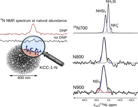
DNP‐enhanced 15N NMR spectra of nitridated DFNS.63
Learning from this DFNS‐oxynitride work, we, in collaboration with Madhu's group, were able to enhance the catalytic activity of SBA‐15‐based solid bases in the Knoevenagel condensation reaction by optimizing the temperature of nitridation (Figure 41) without the need for activation through N‐methylation.64
Figure 41.
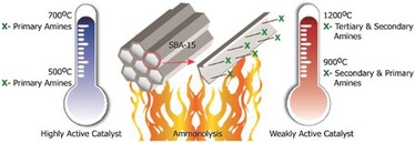
Tuning the catalytic activity by the controlled ammonolysis of SBA‐15.64
DFNS was also used to design efficient solid acid catalysts. Siddiqui et al. prepared recyclable DFNS silica sulfuric acid catalysts by treatment with chlorosulfonic acid. This acid catalyst showed good activity by using a very small amount of the catalyst (98 % conversion in 2 min) for enaminone synthesis.65
Chermahini et al. also synthesized propylsulfonic acid functionalized DFNS and evaluated this catalyst in the dehydration of fructose to produce 5‐hydroxymethylfurfural (Figure 42). The authors found that 5‐hydroxymethylfurfural could be produced in approximately 67 % yield with 68 % selectivity.66
Figure 42.
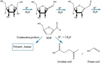
Dehydration of fructose to 5‐hydroxymethylfurfural (HMF) and possible byproducts by acid catalysis. Reprinted with permission from Ref. 66. Copyright 2016 Royal Society of Chemistry.
3.6. DFNS‐supported ionic liquids
DFNS was also functionalized with ionic liquids (ILs). Yang et al. treated the DFNS surface with 1‐methylimidazole having preformed chloropropyl groups.67 These ionic liquids were then used as anchors to load Au NPs (Figure 43), which made them leachproof catalysts. Sadeghzadeh used a similar approach to functionalize DFNS by the reaction of chloropropyl with hexamethylenetetramine.68 DFNS/IL showed good activity in the synthesis of quinazoline‐2,4(1H,3H)‐diones by the reaction of CO2 with 2‐aminobenzonitriles under mild conditions. Sadeghzadeh then further explored this protocol to prepare PbS‐based ionic liquids supported on DFNS.69 This material showed excellent activity in the dehydrogenation of aqueous HCOOH/HCOONa to H2 and CO2 gas with a TOF of 604 h−1 compared to a TOF of 64 h−1 by using Pd/C.69
Figure 43.
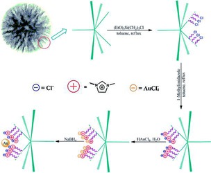
Synthesis of a DFNS‐ionic liquid‐Au nanocatalyst . Reprinted with permission from Ref. 67. Copyright 2014 Royal Society of Chemistry.
A heteropolyacid (HPW)‐containing ionic liquid supported on magnetic DFNS, named Fe3O4/DFNS/IL/HPW, was prepared by using a similar synthetic protocol (Figure 44);70 high loadings of HPW were possible as a result of IL functionalization. This catalyst was efficiently used to synthesize tetrahydrodipyrazolopyridines.71 The catalyst was recyclable up to 10 times without loss of activity, which was attributed to restricted aggregation of the active HPW owing to the ILs on the fibers of DFNS. This catalyst was also used in the synthesis of cyclic carbonate from carbon dioxide and epoxides under mild conditions.71
Figure 44.
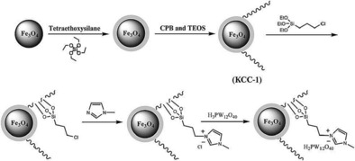
Schematic for the synthesis of Fe3O4/DFNS/IL/HPW. Reprinted with permission from Ref. 70. Copyright 2016 Royal Society of Chemistry.
Similar to the work with ionic liquids, the TEMPO (2,2,6,6‐tetramethylpiperidin‐1‐oxyl) free radical was cleverly generated on the surface of DFNS to design an oxidation catalyst.72 First, DFNS was amine functionalized and then subjected to reductive amination with 4‐hydroxy‐2,2,6,6‐tetramethylpiperdin‐1‐oxyl (4‐oxo‐TEMPO) to yield DFNS/TEMPO. The material catalyzed the oxidation of a wide variety of aliphatic, aromatic, and heterocyclic alcohols in good yields with high selectivities. The catalyst was stable and recyclable up to five times. Because of its small size and fibrous nature, the catalyst particles formed a pseudo‐homogeneous system during catalysis, which improved the reaction efficiency.
3.7. DFNS‐supported organometallic complexes
Organometallic complexes were also supported on DFNS. Tantalum hydride (TaH), the well‐known “Basset's metathesis catalyst”, was prepared by grafting the [Ta(=CHtBu)(CH2 tBu)3] complex onto the fibers of DFNS, followed by hydrogen treatment at 150 °C for 12 h (Figure 45).73 DFNS/TaH efficiently catalyzed the hydrometathesis reaction of olefins with good activity and was stable for several hours. The catalyst was regenerable and reusable with improved activity.
Figure 45.
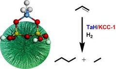
DFNS‐supported tantalum hydride (TaH) for the hydrometathesis of olefins.73
A gold(III) phosphorus complex was also immobilized on DFNS.74 The catalyst showed good activity in the cyclization of propargylic amines with CO2 to provide 2‐oxazolidinones (Figure 46).
Figure 46.
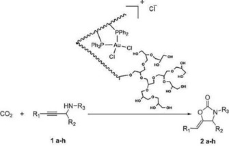
Synthesis of 2‐oxazolidinone by using the DFNS‐supported gold complex. Reprinted with permission from Ref. 74. Copyright 2016 Elsevier B.V.
3.8. DFNS‐supported enzyme
Even an enzyme was supported on DFNS to prepare a supported nano‐biocatalyst. Pang et al. prepared DFNS by modifying the standard DFNS synthetic protocol17 and by using polyvinylpyrrolidone (PVP) as the stabilizing agent for particle growth.75 They then immobilized Candida rugosa lipase (CRL) on the wrinkled silica spheres. The supported CRL was then evaluated as a biocatalyst for biodiesel production through the esterification of oleic acid with methanol. DFNS/CRL was found to be superior to free CRL with an 86 % conversion of oleic acid.
4. Photocatalysis using DFNS
The fibrous morphology of DFNS, which facilitates mass transfer and improves accessibility in thermal catalysis, can also facilitate the separation of light‐generated electron–hole pairs and improve their mobility in photocatalysis. This improved charge separation and transport helps to improve the photocatalytic activity of the materials. In this regard, the use of DFNS as a support for a nanoengineered photocatalyst was first explored by Wang et al. by using graphitic carbon nitride (g‐C3N4)76 and by our group by using titanium dioxide (TiO2).77
The moderate photocatalytic activity of g‐C3N4 could not be improved even by synthesizing nanosized versions owing to some of its inherent structural issues, especially its stability, which led to agglomeration, deformations, and reduced surface accessibility. Wang et al. nanoengineered g‐C3N4 in the form of spheres made up of interconnected sheets by using DFNS as a template.76 Additionally, these sharp sheets (fibers) could have a “lightning‐rod effect”,78 because the electric field is concentrated near the highly curved surface and the tips of the wrinkled fibers. The thermally induced self‐polymerization of cyanamide (adsorbed on the surface of DFNS fibers/sheets) (Figure 47) yielded g‐C3N4 nanospheres (NSs) with morphologies similar to that of DFNS and with good surface area, pore volume, and pore size of 160 m2 g−1, 0.4 cm3 g−1, and 3.8 nm, respectively.
Figure 47.
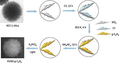
Synthesis of g‐C3N4 nanospheres by using DFNS as a template and cyanamide (CY) as a precursor.76
The g‐C3N4 nanospheres had a Brunauer–Emmett–Teller (BET) surface area of 160 m2 g−1, which was far greater than the surface area of its bulk counterpart (only 9 m2 g−1). Its optical properties were also different from those of its bulk counterpart, with a hypsochromic shift in the photoabsorption edge from λ=465 to 430 nm and a band gap shift from 2.67 to 2.86 eV owing to quantum confinement effects (similar to our observations in the DFNS/TiO2 work).77 This also indicated the improved light‐harvesting nature of the catalysts, particularly in the λ=430–590 nm region because of multiple reflections of incident light within the fibrous structure as well as defect sites associated with the sharp edges of the fibers of g‐C3N4.
Not only light harvesting, but a reduction in the recombination of excitons relative to that observed for bulk g‐C3N4 was also observed in a photoluminescence study. The improved charge separation was due to shortening of the charge migration/diffusion length and electron relocalization on the edges (tips) of the fibers. These attributes of the catalyst led to its excellent photocatalytic activity for hydrogen production by using a Pt cocatalyst. The hydrogen evolution rate by using g‐C3N4 nanospheres as a catalyst and a 3 wt % Pt cocatalyst was 574 μmol h−1, which was approximately 45 times higher than that of its bulk counterpart (12.5 μmol h−1). These results clearly indicate the advantages of the fibrous morphology of DFNS and its applications in the nanoengineering of photocatalysts.76
This DFNS/g‐C3N4 composite was further explored by Takanabe's group by replacing cyanamide with a mixture of melamine and 2,4,6‐triaminopyrimidine as precursors (Figure 48).79 They used a two‐step process: the solution phase deposition of the precursors (monomers) on the DFNS fibers followed by salt‐melt high‐temperature polycondensation. The highest hydrogen evolution rate obtained upon using these materials with 3 wt % Pt cocatalyst was 33 μmol h−1 compared to 574 μmol h−1 obtained by Wang et al.76 These results indicate that, for the synthesis of DFNS/g‐C3N4 with superior photocatalytic activity, cyanamide may be a better precursor than a mixture of melamine and 2,4,6‐triaminopyrimidine.
Figure 48.
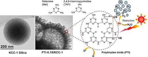
Synthesis of g‐C3N4 nanospheres by using DFNS as a template and a mixture of melamine and 2,4,6‐triaminopyrimidine as precursors. Reprinted with permission from Ref. 79. Copyright 2015 American Chemical Society.
TiO2 is one of the most favored materials that can be used as a photocatalyst.77 However, the use of unsupported TiO2 nanopowder has several drawbacks, such as a small surface area, poor substrate adsorption ability, weak light‐harvesting properties, and difficulty isolating and reusing the catalysts. The issue of isolation and reusability was tackled by immobilizing TiO2 on a silica support. Although all of the supported catalysts allowed for the more efficient isolation and reuse of the catalyst relative to the use of a powdered nano‐TiO2 suspension, the catalytic activity remained poor because of the poor accessibility of the active sites (TiO2). This result implied that the support played a very important role in the design of the photocatalysts allowing for a greater loading of TiO2 with a high substrate adsorption capacity and, more importantly, accessible active sites was needed. In this regard, we designed and synthesized high surface area TiO2 coated on the fibers of fibrous nanosilica (DFNS/TiO2) (Figure 49).77 The synthesis of DFNS/TiO2 was achieved by the deposition of a titanium precursor on DFNS fibers by using atomic layer deposition (ALD) and then oxidizing the material to produce a TiO2 coating. To compare the DFNS/TiO2 materials with conventional materials, SBA‐15/TiO2 and MCM‐41/TiO2 were also prepared by using the same ALD and heat‐treatment procedure. Notably, we observed the formation of small and monodispersed TiO2 nanoparticles after heat treatment with variable sizes.
Figure 49.
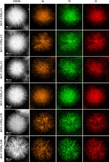
Scanning transmission electron microscopy (STEM) and EDS mapping of the DFNS/TiO2 series materials with varied ALD cycles of TiO2. Reprinted with permission from Ref. 77. Copyright 2016 American Chemical Society.
We found that the DFNS/TiO2 catalysts had an array of advantages over conventional silica‐based TiO2 catalysts, such as MCM‐41 and SBA‐15 (Figure 50), in terms of the following: one, a uniform conformal coating, high TiO2 loading, less reduction in surface area, and better accessibility of active sites; two, the presence of TiO2 on the DFNS fibers, for which most of the excitons were on the surface and readily available for catalysis, and this allowed for excellent catalytic performance (Figure 50 c, d) (e.g., conversion, kinetics, and stability); three, enhanced light‐harvesting properties through scattering and reflecting a large amount of incident light owing to the fibrous structure of the material; four, high surface area, which facilitated the adsorption of a large amount of dye molecules during dye degradation. The combination of the unique textural and morphological properties of DFNS, TiO2 nanoparticle formation, and their size quantization were the reasons for the improved photocatalytic activity of the DFNS/TiO2 catalysts.77
Figure 50.
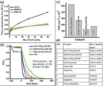
Advantages of using DFNS over MCM‐41 or SBA‐15 as a support for TiO2: a) TiO2 loading in weight % per unit surface area, b) photocatalytic dye degradation of rhodamine B (Rh‐B) under UV light, c) turnover frequency (TOF) values, and d) comparison with reported silica‐supported TiO2 catalysts. Adapted with permission from Ref. 77. Copyright 2016 American Chemical Society.
5. Energy Harvesting using DFNS for Solar Cells
As presented in the work of Wang et al.76 and our group,77 the fibrous nature of DFNS‐based g‐C3N4 and TiO2 increased the light‐harvesting ability, provided better charge separation, and improved the adsorption of dye and water molecules, which in turn increased the photocatalytic performance. Jang et al. used these attributes of DFNS to improve the performance of dye‐sensitized solar cells (DSSCs) by using TiO2‐coated DFNS as a light scatterer in DSSCs—an impressive report and the first of its kind (Figure 51).80 They compared the light‐scattering capabilities of these DFNS/TiO2 materials (they named them WSNs) with solid silica spheres of the same size. The 220 nm WSNs exhibited a higher reflectance than similarly sized silica nanoparticles in the 400 to 900 nm wavelength range. This result indicated the role of the fibrous morphology in increasing light scattering owing to the multiple light‐scattering events at the abundant particle (fiber)–air interfaces. Such intraparticle scattering is minimal in conventional silica nanoparticles. Notably, the 220, 320, and 430 nm WSNs showed characteristic reflectance bands at λ=450, 700, and 850 nm, respectively. The authors suggested that these bands could be due to Mie scattering, for which the effective light scattering is approximately half the wavelength of the incident light.
Figure 51.
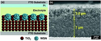
DSSC design containing DFNS/TiO2 as a scatterer (top layer): a) schematic illustration and b) cross‐sectional SEM image (the DFNS/TiO2 layer is 3.5 μm and the TiO2 nanoparticle layer is 7 μm). FTO=fluorine‐doped tin oxide. Reprinted with permission from Ref. 80. Copyright 2016 Royal Society of Chemistry.
The photovoltaic performance of these assembled DSSCs was evaluated, and they showed a remarkable improvement in the short‐circuit current (J sc), although the open‐circuit voltage (V oc) and the fill factor (FF) did not change (Figure 52). The 430 nm sized WSN showed the best performance with a power conversion efficiency (PCE) value of 9.53 % and a PCE enhancement of 30.19 relative to a reference cell.80
Figure 52.
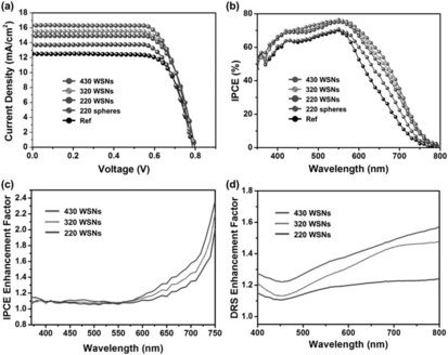
a) Current density–voltage (J–V) characteristics and b) incident photon‐to‐current efficiency (IPCE) spectra of DSSCs based on WSNs with various sizes and 220 nm solid silica nanospheres. c) IPCE enhancement factor (IPCEsample/IPCE220spheres) and d) diffuse reflectance spectroscopy (DRS) enhancement factor (DRSsample/DRS220spheres) based on the 220 nm spheres. Reprinted with permission from Ref. 80. Copyright 2016 Royal Society of Chemistry.
The use of TiO2‐coated fibrous nanosilica (DFNS) as a scatterer in DSSCs was also reported by Kang et al. (Figure 53).81 They studied the effect of the interwrinkle distance of the DFNS fibers on the performance of DSSCs based on scattering/light‐harvesting ability as well as improved dye loading. They observed that larger interwrinkle distances enhanced the mass transport of dye molecules to even deeper sections of the nanospheres and that it also affected the reflectance properties (owing to differences in overall refractive indices). They were also able to correlate the photovoltaic performance with a change in the morphology of the nanospheres, although the efficiency was moderate relative to that observed by Wang et al.76
Figure 53.
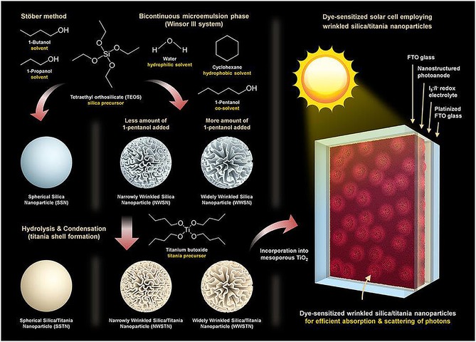
TiO2‐coated fibrous nanosilica as a scatterer in DDSCs. Reprinted with permission from Ref. 81. Copyright 2016 Nature Publishing Group (NPG).
In addition to water splitting, dye degradation, and solar cells, DFNS was also used in photocatalytic organic transformations. Sadeghzadeh reported the use of DFNS without any functionalization for the synthesis of triazolo[1,2‐a]indazoletriones at room temperature by using visible light.82 Notably, pure DFNS was able to catalyze the reaction, and good conversion and catalyst recyclability were achieved.
6. Magnetic DFNS
Magnetically recoverable catalysts have witnessed explosive growth in green‐chemistry applications.83 Yu et al. made DFNS magnetic by designing core–shell Fe3O4/SiO2/DFNS structures.84 First, they coated Fe3O4 with a thin layer of silica, and these Fe3O4/SiO2 were used as seeds on which DFNS was grown by using the typical synthetic procedure (Figure 54). Fe3O4/SiO2/DFNS consisted of a 170 nm Fe3O4 core coated with a 20 nm silica shell and then another fibrous silica shell of approximately 150 nm (Figure 55). The magnetization study of this material showed no hysteresis in the curves and a saturation magnetization value of 31 emu g−1, which indicated its supermagnetism. Its BET surface area and pore volume were 213 m2 g−1 and 0.45 cm3 g−1, respectively, which were lower than those of the parent DFNS but considerably larger than those of the pure magnetic material with only a solid core. It showed an excellent adsorption capacity for methylene blue dye (78 %) within 5 min. These results indicated that the fibrous channels and larger pores of the catalyst assisted quick adsorption of the dye molecules and that the high surface area of the catalyst increased its adsorption capacity.
Figure 54.

Synthetic scheme for core–shell Fe3O4/SiO2/DFNS materials. Reprinted with permission from Ref. 84. Copyright 2013 Elsevier B.V.
Figure 55.
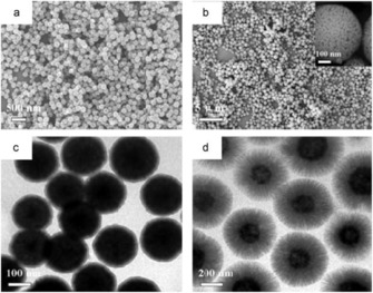
SEM images of a) Fe3O4 and b) Fe3O4/SiO2/DFNS and TEM images of c) Fe3O4/SiO2 and d) Fe3O4/SiO2/DFNS. Reprinted with permission from Ref. 84. Copyright 2013 Elsevier B.V.
This magnetic DFNS was then used to prepare magnetic DFNS/Pd catalysts by using our APTS approach.32 Ma's group functionalized Fe3O4/SiO2/DFNS with APTS to create surface amino groups and then loaded the material with Pd NPs (Figure 56).85 Its excellent catalytic activity could be quantified by the ratio of the normalized rate constant between Pd/Fe3O4@SiO2@KCC‐1 and Pd/SBA‐15, which was found to be 23.55 times higher in the case of Pd/Fe3O4@SiO2@KCC‐1 in the reduction of 4‐nitrophenol by NaBH4 and in the Suzuki cross‐coupling reaction of a range of aryl bromides and chlorides. Additionally, the catalyst was magnetically recoverable and was reused over at least for five cycles without any significant change in activity.
Figure 56.
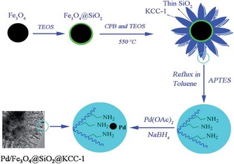
Schematic for the synthesis of the Pd/Fe3O4@SiO2@DFNS nanocatalyst. Reprinted with permission from Ref. 85. Copyright 2014 Royal Society of Chemistry.
This synthetic protocol was then extended by Dong et al. to prepare magnetic DFNS‐supported Au NPs, denoted Au/γ‐Fe2O3@SiO2@DFNS (Figure 57).86 This catalyst exhibited higher activity for the reduction of 4‐nitrophenol to 4‐aminophenol (Figure 58) than conventional Au nanocatalysts supported on graphene, carbon, and magnetic carbon. For example, this catalyst had an apparent rate constant (1.45×10⁻² s−1) that was 2.5 times higher than that of other Au‐contained catalysts. In addition, the catalyst was magnetically recoverable and stable for reuse over at least six cycles.
Figure 57.
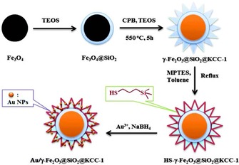
Schematic for the synthesis of Au/γ‐Fe2O3@SiO2@DFNS. MPTES=3‐mercaptopropyltrimethoxysilane. Reprinted with permission from Ref. 86. Copyright 2015 Royal Society of Chemistry.
Figure 58.
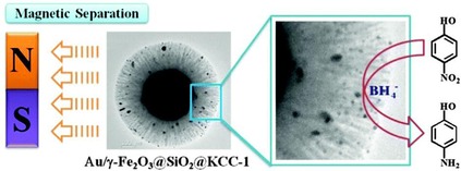
Reduction of 4‐nitrophenol to 4‐aminophenol over Au/g‐Fe2O3@SiO2@DFNS and magnetic catalyst recycling. Reprinted with permission from Ref. 86. Copyright 2015 Royal Society of Chemistry.
Not only metallic nanoparticles but bimetallic NPs were also decorated on magnetic DFNS fibers. Ma's group synthesized Ni@Au/DFNS nanocatalysts by loading preformed Ni@Au core–shell (Ni as the core and Au as the shell) nanoparticles on mercapto‐functionalized DFNS.87 As Au was used as the shell, a reduced amount of Au was needed to catalyze the reduction of 4‐nitrophoenol and 2‐nitroaniline with superior activity. Additionally, the use of Ni as the core made the catalysts superparamagnetic (Figure 59), which made the catalysts magnetically separable. Using a similar approach, Ma's group also prepared DFNS‐supported Ni@Pd core–shell nanocatalysts and evaluated them for the catalytic reduction of 4‐nitrophenol and for the hydrodechlorination of 4‐chlorophenol.88
Figure 59.
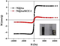
Magnetization curves of Ni@Au NPs and Ni@Au/DFNS at room temperature. Reprinted with permission from Ref. 87. Copyright 2014 Elsevier B.V.
7. DFNS‐Based Hybrid/Composite Materials
Hybrid or composite materials of DFNS with tunable chemical and physical properties could have excellent applications in various fields. In this regard, Aghakhani et al. prepared DFNS/nylon‐6 composites by using an electrospinning technique.89 They applied high voltage to the dispersion of DFNS spheres (in formic acid) in nylon‐6 solution to yield nonwoven composite fibers of DFNS/nylon‐6. The nanospheres were arranged along the fibers of nylon‐6 with good distribution even at high concentrations of silica (50 % w/w) (Figure 60). They observed a reduction in the surface area, possibly as a result of coating DFNS by a polymeric film.
Figure 60.
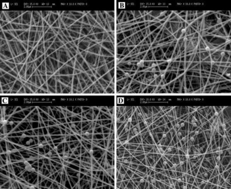
SEM images of DFNS/nylon‐6 composite nanofibers with varying DFNS concentrations: a) 0, b) 20, c) 33, and d) 50 % w/w. The scale bars are 2.00 μm Reprinted with permission from Ref. 89. Copyright 2015 Springer.
A fibrous 3 D carbon material was prepared by Yi et al. by using DFNS as a hard template.90 Owing to their resemblance to sea urchin (Echinometra mathaei), they called this carbon structure carbon nano‐Echinometra mathaei (CNE), although they were not exactly the same as Echinometra mathaei, which have sharp tips arising from a central solid core (DFNS has no solid core). A carbon precursor (phenolic resin) filled the channels of DFNS from the inside out, and the overall shape and morphology were retained during the carbonization step (Figure 61). After removal of the silica, CNE had a pseudohollow structure. The CNE surface area was approximately 1570 m2 g−1, and it was made up of mesopores and 20 % micropores. They then designed catalysts for the hydrolytic hydrogenation of cellulose by coating these CNEs with Pt nanoparticles. The Pt/CNE catalysts showed high performance as well as high selectivity. On the surface of Pt metal, the spillover effect increased because of the abundance of oxygen groups on CNE, which resulted in an excellent supply of H+ for the hydrolysis step. The authors claimed that this catalyst was the best‐performing catalyst at the time for the production of hexitols from cellulose.90
Figure 61.
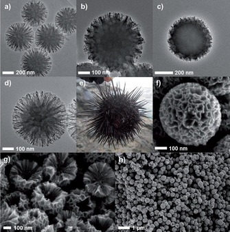
HRTEM images of a) the DFNS silica template, b) the DFNS carbon composite after drying, c) the DFNS carbon composite after aging, and d) CNE. e) An image of a real Echinometra mathaei. SEM images of f) a particle of CNE, g) the cross‐section of CNE, and h) their large‐scale view.90
8. CO2 Capture using DFNS
CO2 emissions need to be reduced urgently to evade potentially dangerous climate change.91, 92 Therefore, the demand for CO2 sorbents with high capture capacity and faster kinetics (rate of CO2 capture) is continuously growing. This can be achieved by developing solid sorbents with improved efficiency and better stability (unlike liquid sorbents). The functionalization of solid supports such as porous silica by various amines is one of the best ways to create next‐generation CO2 sorbent materials. Although several studies reported that the functionalization of conventional silica supports (such as MCM‐41 and SBA‐15) resulted in high amine loadings,91, 92 one of the critical disadvantages was the drastic decrease in their textural properties (surface area, pore volume, etc.), and hence, there was not a significant improvement in the CO2 capture capacity and kinetics owing to poor diffusion and restricted accessibility of the amine sites.91, 92
To overcome this challenge, we envisioned DFNS as a possible good support to design efficient CO2 sorbents.93, 94 Owing to its fibrous and open structure, it can have high amine loadings, with minimal reduction in surface area and, hence, improved accessibility of the amine sites. To study these hypotheses, functionalization of DFNS by using various amines (Figure 62) was undertaken.93 A range of amine molecules such as propylamine (PA), propylethylene diamine (PEDA), propyldiethylene triamine (PDETA), tetraethylene pentamine (TEPA), and polyethylenimine (PEI) with both low and high molecular weights (LMW and HMW) were loaded on DFNS by physisorption and by covalent attachment (Figure 62).
Figure 62.
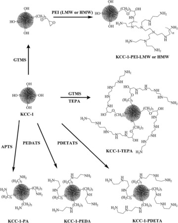
Functionalization of DFNS with various amines. PEDATS=please define, PDETATS=N‐(3‐trimethoxysilylpropyl)diethylenetriamine. Reprinted with permission from Ref. 93. Copyright 2016 Royal Society of Chemistry.
DFNS‐TEPAads was found to be superior to its MCM‐41 counterpart with respect to textural stability, CO2 capture capacity, rate of adsorption, and thermal stability (Figure 63). Although DFNS‐TEPAads showed 84 and 67 % reduction in surface area and pore volume, respectively, after amine functionalization, these values were lower than the 97 % reduction in surface area and 98 % reduction in pore volume of MCM‐41‐TEPAads. Hence, the CO2 capture capacity of MCM‐41‐TEPAads was 12.1 wt % compared to 15.5 wt % for the DFNS sorbent at 50 °C. Even though the surface area of the DFNS‐based sorbent was significantly reduced, because of its fibrous nature, most of the amines sites were on the surface and accessible to CO2, which was not the case for MCM‐41 with a tubular porous structure. Therefore, despite possessing double the initial surface area, the MCM‐41 sorbent was inferior to DFNS. Notably, the total CO2 capture capacity after 21 cycles under humid conditions was 91.5 mmol g−1 for DFNS‐TEPAads, whereas MCM‐41‐TEPAads captured only 73.1 mmol g−1.93 Lai and co‐workers also made a similar observation that TEPA loaded on wrinkled silica was a good CO2 sorbent.95 However, further improvements are needed in terms of CO2 capture values for DFNS‐based sorbents.
Figure 63.
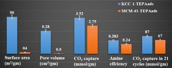
Effect of support morphology on CO2 capture for DFNS versus MCM‐41. Reprinted with permission from Ref. 93. Copyright 2016 Royal Society of Chemistry.
We also achieved the amine functionalization of DFNS (as well as that of MCM‐41 and SBA‐15) by a thermal ammonolysis (nitridation) process (Figure 64).94 DFNS‐oxynitrides were used as sorbents for CO2 capture and showed several advantages, such as faster kinetics, that is, faster adsorption/desorption cycle, and thus increased capture of CO2 in a shorter amount of time. Regeneration and reuse of the sorbents was possible with excellent mechanical strength. It was shown to have high thermal stability (in inert and oxidative environments). However, the CO2 capture capacity was lower than that of either MCM‐41 or SBA‐51, and none of them were stable under moist conditions.94
Figure 64.
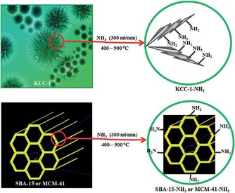
Synthesis of silicon oxynitrides by the ammonolysis of DFNS, SBA‐15, and MCM‐41. Reprinted with permission from Ref. 94. Copyright 2012 Royal Society of Chemistry.
9. Biomedical Applications using DFNS
9.1. Drug delivery using DFNS
Controlled drug‐delivery systems (CDDSs) using various inorganic nanomaterials, including nanosilica, have been of great interest owing to enhanced therapeutic efficacy and reduced side effects. The size, shape, and morphology of these nanocarriers have great influence on their cell permeation, nucleus entry, distribution within the cell, cellular uptake (drug loading and release), and biocompatibility. Thus, precise control over these textural parameters of silica nanoparticles is key for the development of CDDSs. Conventional silica nanoparticles do not allow such control, whereas DFNS does.17, 18, 19 DFNS, because of its fibrous morphology, monodispersed particles, varied surface chemistry/functionalization possibilities, and large surface area, could be a promising nanocarrier for various therapeutic agents. Conventional nanosilica spheres have limited surface area for the loading of biomolecules, whereas DFNS has a larger surface area. Notably, tunable pore size/fiber density is favorable for improving the loading and mass‐transfer efficiency, even for larger biomolecules such as proteins, enzymes, DNA, and siRNA.
In this regard, both pure and magnetic DFNS were used to load the anticancer drug doxorubicin hydrochloride (DOX) for its delivery to cells.96, 97 Magnetic DFNS (named FMSMs), as a result of its fibrous nature (Figure 65), had a larger surface area than pure iron oxide nanoparticles, which thus increased the drug‐loading efficiency.96 The in vitro drug release of DOX‐Fe3O4/FMSMs occurred over two stages: rapid release in the initial hour and then slow release over 20 h (Figure 66). The initial release was attributed to the physically adsorbed drug (weakly bound to the surface), whereas the slow release was attributed to the drug adsorbed in the fibrous channels of DFNS (FMSMs) as well as their strong interaction with silica surface silanols. The initial burst of DOX may be beneficial as an initial dose to kill HeLa cells, and then the slow‐released drug can prevent further proliferation of cancerous cells. This result clearly indicates that DFNS can be efficiently used as drug‐delivery carrier.
Figure 65.
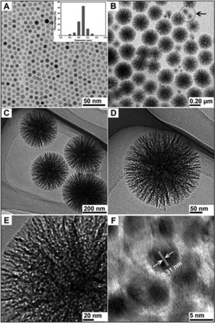
a) TEM image of 9 nm Fe3O4 used as seeds. b–e) TEM images and f) HRTEM image of Fe3O4/DFNS, renamed Fe3O4/FMSMs. Reprinted with permission from Ref. 96. Copyright 2011 Royal Society of Chemistry.
Figure 66.
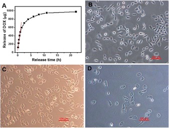
a) Drug‐release profile of DOX‐Fe3O4/FMSMs in phosphate‐buffered saline (PBS), b) the nuclei of blank SKOV3 cells and the nuclei of SKOV3 cells incubated with DOX‐Fe3O4/FMSMs for c) 8 h and d) 24 h. Reprinted with permission from Ref. 96. Copyright 2011 Royal Society of Chemistry.
The authors also showed that pure DFNS without an iron oxide core could be used as a drug carrier.97 They prepared DFNS with different TEOS/CTAB ratios, named FMSMs‐A, FMSMs‐B, FMSMs‐C, and FMSMs‐D, and they then evaluated DOX release and biocompatibility (Figures 67 and 68). The DOX release profile of FMSMs‐D was similar to the two‐stage profile discussed in their previous work.96 More than 90 % of L929 fibroblast cell viability was observed, which indicated the good biocompatibility of the FMSMs‐D materials.
Figure 67.
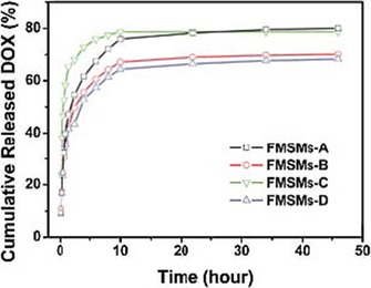
DOX release from FMSMs‐A, FMSMs‐B, FMSMs‐C, and FMSMs‐D. Reprinted with permission from Ref. 97. Copyright 2012 Royal Society of Chemistry.
Figure 68.
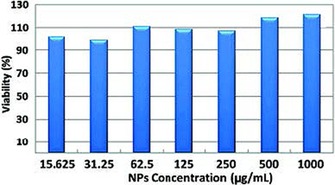
FMSMs‐D biocompatibility using an MTT [3‐(4,5‐dimethylthiazol‐2‐yl)‐2,5‐diphenyltetrazolium bromide] assay, incubated with L929 fibroblast cells for 24 h. Reprinted with permission from Ref. 97. Copyright 2012 Royal Society of Chemistry.
Du et al. used DFNS‐like uniform dendrimeric amino‐functionalized silica with hierarchical pores (HPSNs‐NH2) as nanocarriers.98 HPSNs‐NH2 was functionalized by low‐molecular‐weight PEI (HPSNs‐PEI) through a succinic anhydride linker to improve its biocompatibility as well as its interaction with drug molecules (Figure 69). Anticancer drugs, topotecan (TPT), and nucleic acids (pEGFP‐N1 plasmid DNA, p‐DNA), were used as model drugs in this study (Figure 70). HPSNs‐PEI showed high coloading (9.81 μg mg−1) of the drug and nucleic acid. It also showed good biocompatibility, excellent p‐DNA delivery (≈80 % in less than 50 h), and high transfection efficiencies of 21.6, 35.3, and 47 % by using different HPSNs‐PEI/p‐DNA mixing ratios into HeLa cells. Notably, it showed extraordinary ability to kill cancer cells through synergetic effects from the codelivery of the anticancer drug and nucleic acid.98 PEI‐functionalized DFNS was also used by Qiao et al. and showed good potential for the intracellular delivery of DOX.99 They observed autofluorescence without any fluorescent agent, which could be used for particle tracking.
Figure 69.
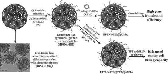
Design of hybrid HPSNs‐PEI and their use as nanocarriers for drug delivery.98
Figure 70.
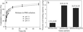
a) The in vitro cumulative TPT release profiles of HPSNs‐PEI in PBS at various pH values. b) Loading capacity of nucleic acid (pDNA). Reprinted with permission from Ref. 98. Copyright 2013 Wiley‐VCH.
DFNS, such as periodic mesoporous organosilica (PMO), which has fibers made up of silica with benzene rings, was also synthesized and used as a nanocarrier.100 They were prepared by using TEOS and 1,4‐bistriethoxysilylbenzene as the silica precursor. The hydrophobic wrinkled PMO was then loaded with the hydrophobic anticancer drug paclitaxel (Figure 71). Wrinkled PMO showed 11.5 % better drug loading efficiency than conventional mesoporous silica (Figure 72). Release of the drug was slow and sustained for up to 5 days, which indicated the potential of DFNS‐PMO for the delivery of hydrophobic drugs.100
Figure 71.
Paclitaxel‐loaded wrinkled periodic mesoporous organosilica. Reprinted with permission from Ref. 100. Copyright 2015 Springer.
Figure 72.
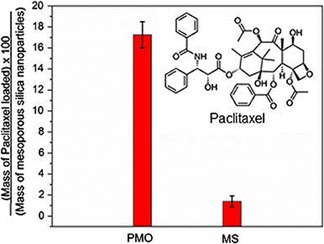
Paclitaxel drug uptake by periodic mesoporous organosilica (PMO) and mesoporous silica (MS) nanoparticles. Reprinted with permission from Ref. 100. Copyright 2015 Springer.
9.2. DNA and gene delivery using DFNS
Asefa and co‐workers used DFNS for DNA loading and gene delivery.101 DFNS was first selectively functionalized with organoamine groups on the walls of fibrous channels or the external surface or both (Figure 73). For comparison, MCM‐41 silica was also functionalized by using the same protocol. These materials were then evaluated for salmon DNA adsorption and gene delivery. The results indicated that functionalized DFNS had a higher DNA adsorption capacity than functionalized MCM‐41 (Figure 74), which was attributed to the large pores, wide pore mouths, and fibrous pore network of DFNS, all of which made it more accessible for the diffusion of DNA molecules. The cylindrical pores of functionalized MCM‐41 were blocked by the DNA molecules, which restricted the accessibility of the inner surface. A toxicity study indicated that the DFNS‐based materials were biocompatible.101
Figure 73.
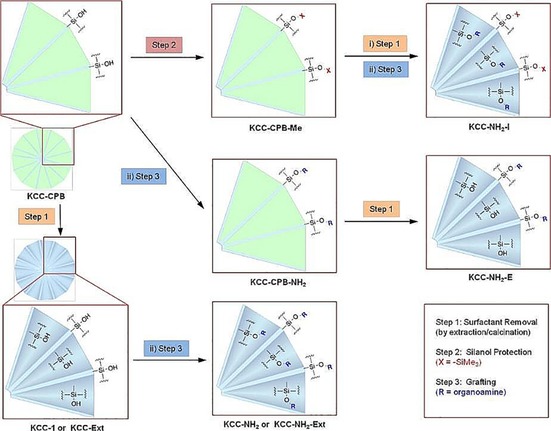
Schematic for the preparation of KCC‐NH2, KCC‐NH2‐Ext, KCC‐NH2‐ E, and KCC‐NH2‐I. Reprinted with permission from Ref. 101. Copyright 2014 American Chemical Society.
Figure 74.
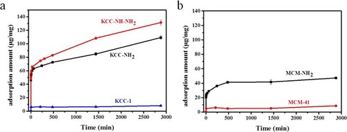
Adsorption of salmon DNA in a) KCC‐1, KCC‐NH2, and KCC‐NH‐NH2 and in b) MCM‐41 and MCM‐NH2. Reprinted with permission from Ref. 101. Copyright 2014 American Chemical Society.
DFNS was also used to deliver cytosine‐phosphate‐guanosine oligodeoxynucleotides (CpG ODNs).102 DFNS with three different particle sizes (i.e., 97, 205, and 535 nm) was functionalized with APTS to produce amine‐functionalized DFNS, named DMSN97‐NH2, DMSN205‐NH2, and DMSN535‐NH2 (in which DMSN stands for dendritic mesoporous silica nanoparticles). CpG ODNs, with strong immunostimulatory activity (used in the treatment of various diseases such as cancer, allergies/asthma, and infectious diseases), were then loaded on the aminated DMSN. Detailed studies for serum stability, in vitro cytotoxicity, cellular uptake, and cytokine interleukin‐6 (IL‐6) induction showed no cytotoxicity to raw 264.7 cells and improved serum stability of CpG ODNs. These amine‐functionalized DFNS were taken up by cells in endolysosomes (Figure 75), which indicated that they could be used as promising alternatives for CpG ODN delivery.
Figure 75.
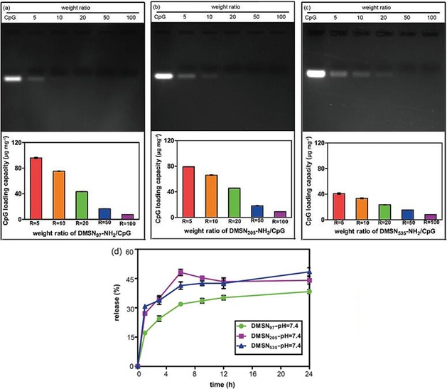
Top) Agarose gel electrophoresis of the supernatants after binding CpG ODN to aminated DMSNs at various weight ratios of a) DMSN97‐NH2/CPG, b) DMSN205‐NH2/CpG, and c) DMSN535‐NH2/CpG. Bottom) CpG ODN loading capacities on aminated DMSNs at various weight ratios of a) DMSN97‐NH2, b) DMSN205‐NH2/CpG, and c) DMSN535‐NH2/CpG and d) the release percentages of CpG ODN from the DMSN97‐NH2/CpG, DMSN205‐NH2/CpG, and DMSN535‐NH2/CpG complexes. Reprinted with permission from Ref. 102. Copyright 2016 American Scientific Publishers.
9.3. Antimicrobial enzyme delivery using DFNS
DFNS was also used for the delivery of an antimicrobial enzyme.103 Lysozyme, which has antimicrobial activity toward Gram‐positive bacteria, is limited by its poor stability and weak binding affinity with the surface of bacteria. DFNS, such as MSN, was prepared by using fluorocarbons (FCs) of various chain lengths, named MSN‐FCx‐Ry, in which x and y represent the length of the fluorocarbon chain and the molar ratio of the anion to the please define CTAB template.103 In addition to the loading and release of lysozyme in MSN, their antibacterial activity was studied by using E. coli. Untreated bacteria grew exponentially for up to 3 days, whereas lysozyme‐loaded MSNs showed enhanced bacterial inhibition (Figure 76). Notably, lysozyme‐loaded MSNs‐FC8‐R0.15 maintained complete inhibition toward E. coli for 5 days. The bacterial‐killing activity was also confirmed by an agar plate test (Figure 76). These results indicated that the fibrous morphology of the nanocarrier improved the bacteria's membrane adhesion, which thus improved its performance. Similarly, Wan et al. used Ag‐coated DFNS as an antibacterial agent, which showed excellent activity for both E. coli and S. aureus having a minimum inhibitory concentrations of 36.55 and 73.10 mg L−1 and minimum bactericidal concentrations of 48.55 and 97.10 mg L−1.104
Figure 76.
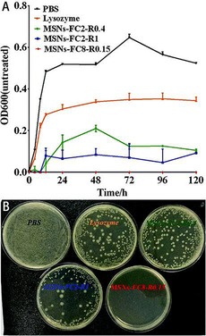
a) Bacterial growth kinetics of E. coli incubated with free lysozyme and MSNs loaded with lysozyme and b) a photograph of the agar plates of E. coli and MSNs loaded with lysozyme suspension with concentration of 500 mg mL−1 after 5 days of incubation. Reprinted with permission from Ref. 103. Copyright 2016 Royal Society of Chemistry.
9.4. Ayurvedic drug delivery using DFNS
The Ayurvedic drug curcumin (Cur) was also effectively loaded on DFNS, named dendritic mesoporous silica nanoparticles (DMSNs).105 Curcumin derived from turmeric has been used daily in India for thousands of years and was first cultivated in Harappa as early as approximately 3000 B.C. It is also highly valued in Ayurveda owing to its extraordinary healing activity for cuts, wounds, inflammations, and skin diseases. Its medicinal potential was recognized in Sushruta Samhita dating back to 250 B.C.106 For loading curcumin, DMSNs approximately 63 nm in size were first functionalized with folic acid (FA) to achieve selective targeting of cancer cells (Figure 77). FA has a strong chemical attraction to folate receptors to overexpress glycosylphosphatidylinositol‐linked proteins in tumors. For the pH‐responsive release of Cur, DMSNs‐FA were loaded with calcium hydroxide, and then calcium loading was achieved by chelating with divalent calcium (Figure 77). The as‐prepared Cur‐Ca@DMSNs‐FA was dispersed very well, and its drug delivery to breast cancer cells was also efficient (Figure 78). The authors also observed that Cur‐Ca@DMSNs‐FA inhibited cell proliferation, increased the generation of intracellular reactive oxygen species (ROS), decreased the mitochondrial membrane potential, and enhanced cell‐cycle retardation. The material was biocompatible. These results indicate the advantages of combining traditional Ayurvedic medicine with advanced nanocarriers for the development of modern drug formulations.
Figure 77.
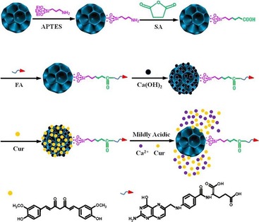
Synthesis of Cur‐Ca@DMSNs‐FA and its pH‐responsive drug release. SA=succinic anhydride. Reprinted with permission from Ref. 105. Copyright 2016 American Chemical Society.
Figure 78.
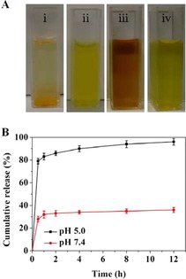
a) Solubility of free Cur and Cur‐Ca@DMSNs‐FA in different solvents: i) Free Cur (2 mg) in PBS at pH 7.4 (insoluble), ii) free Cur (2 mg) in EtOH (fully soluble), iii) Cur‐Ca@DMSNs‐FA (25 mg, equivalent of 2 mg Cur) in PBS at pH 7.4 (dispersed), and iv) Cur‐Ca@DMSNs‐FA (25 mg) in PBS (pH 5.0). b) Cur release profiles from Cur‐Ca@DMSNs‐FA in PBS at pH 5.0 and 7.4 containing Tween‐80 (10 % v/v). Reprinted with permission from Ref. 105. Copyright 2016 American Chemical Society.
9.5. Photothermal ablation therapy using DFNS
In addition to the development of a drug‐delivery system, the development of multifunctional CDDSs that deliver the drug and respond to external stimuli such as light or heat seem to be the way forward in the field of nanomedicine. For example, photothermal ablation (PTA) therapy uses heat produced from the conversion of light energy to kill cancer cells in a selected region. Fibrous nanosilica (DFNS) was used in the development of a PTA‐based therapy.107 Polypyrrole (PPy), a near‐infrared (NIR) light‐absorbing polymer, was loaded inside the fibers of DFNS nanoparticles, denoted DSNs (dendrimer such as silica nanoparticles), by the FeCl3‐assisted in situ polymerization of pyrrole monomers. After surface modification by polyethylene glycol (PEG) to improve biocompatibility and stability under physiological conditions, the anticancer drug doxorubicin (DOX) was loaded (Figure 79).107
Figure 79.
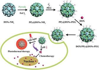
Design and preparation of DOX/PPy@DSNs‐PEG for PTA therapy. Reprinted with permission from Ref. 107. Copyright 2016 Royal Society of Chemistry.
The UV/Vis‐NIR absorbance spectrum confirmed the high NIR absorption (between λ=700 and 1100 nm) by PPy@DSNs‐PEG (Figure 80), which indicated its potential for use in PTA therapy. The photothermal effect of the PPy@DSNs‐PEG suspension was concentration and laser power density dependent. The temperature could be elevated up to 50.9 °C, and its photothermal activity was stable, as observed over three on–off laser cycles (Figure 80).107
Figure 80.
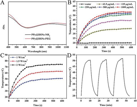
a) UV/Vis absorption spectra of PPy@DSNs‐NH2 and PPy@DSNs‐PEG. Photothermal heating curves of PPy@DSNs‐PEG aqueous dispersions b) at different concentrations under λ=808 nm laser irradiation (power density=1 W cm−2). c) 250 mg mL−1 dispersions at various power densities. d) Change in temperature of PPy@DSNs‐PEG aqueous dispersions (250 mg mL−1) over laser on–off cycles under λ=808 nm laser irradiation (power density=1 W cm−2). Reprinted with permission from Ref. 107. Copyright 2016 Royal Society of Chemistry.
A BET surface area of 165.9 m2 g−1 was used to load DOX with a loading efficiency (LE) of 86.92 % and an entrapment efficiency (EE) of 16.07 % (Figure 81). The fibrous nature of silica, as well as the π–π stacking interaction of PPY with DOX, was the reason for such high LE and EE values. DOX release was rapid over pH 5.0 to 7.4 at 41.75 and 5.63 %, respectively. At low pH values, protonation of the DOX amino groups made it positively charged, which increased the release. Notably, the photothermal effect by NIR irradiation enhanced DOX release at pH 5.0, which indicated the advantage of PTA therapy. The authors attributed this improved performance to weakened binding between DOX and PPy and reduced electrostatic interaction of DOX and fibrous silica by increased local temperature.107
Figure 81.
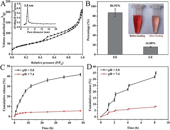
a) N2 sorption isotherms and pore‐size distribution curves (inset). b) DOX loading efficiency (LE) and entrapment efficiency (EE), DOX solutions before and after loading (inset) of PPy@DSNs‐PEG. Cumulative release profiles of DOX from DOX/PPy@DSNs‐PEG at different pH values c) without and d) with 1 W cm−2 NIR irradiation. Reprinted with permission from Ref. 107. Copyright 2016 Royal Society of Chemistry.
9.6. Delivery of chemo‐ and radiotherapeutics simultaneously using DFNS
Notably, DFNS was used in the development of a novel delivery vehicle that delivered chemo‐ and radiotherapeutics simultaneously.108 DFNS was loaded with a 1,2‐dioleoyl‐sn‐glycero‐3‐phosphocholine (DOPC) lipid‐coated/uncoated platinum drug and holmium complex, denoted 165Ho‐MS np, which after neutron activation became radioactive (i.e., 166Ho‐MS np) (Figure 82).108 It showed radioactivity of 213.6 μCi mg−1 after neutron activation for 1 h (thermal neutron flux of 3.5×10¹² neutrons cm−2 s−1). Controlled release of the drugs from the DFNS was possible for over 40 h. Balkus Jr. et al. also loaded the Pt drug cisplatin and nitric oxide (NO) in amine‐functionalized DFNS and effectively used it in the treatment of nonsmall cell lung cancer.109
Figure 82.
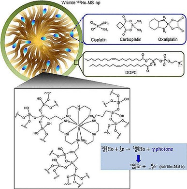
DOPC lipid‐coated platinum drug‐loaded holmium‐165‐containing DFNS. Reprinted with permission from Ref. 108. Copyright 2014 AIP Publishing.
9.7. Real‐time imaging using DFNS
Hong and co‐workers prepared multifunctional CDDSs by using magnetic DFNS and fluorescent labeling for drug delivery as well as real‐time imaging.110 Magnetic and fluorescent DFNS was prepared with iron‐oxide seeds and fluorescein dye by using the standard protocol for the synthesis of DFNS. The resulting material possessed good magnetic (saturation magnetization value of 11.44 emu g−1) and optical properties (with a clearly resolved excitation band at λ=491 nm and an emission band at λ=526 nm). A cytotoxicity study concluded that these materials could be used safely for live‐cell imaging and magnetic resonance imaging at less than 10 ppm concentration. Fluorescence imaging (Figure 83) indicated that these NPs could be used for cell imaging, for which green fluorescence was observed in the cytoplasm and even inside the nuclei owing to the internalization and uniform distribution of the NPs within the cells.
Figure 83.
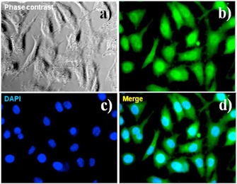
Fluorescence micrographs (400×) of L929 cells treated with 10 ppm magnetic and fluorescent DFNS for 1 h, followed by counterstaining of cell nuclei with 10 μmol L−1 DAPI. a) Phase contrast image of the cells colabeled with the composites and DAPI. b, c) Fluorescence images of the cells collected at λ exc=450 nm (green, from the composites) and λ exc=350 nm (blue, from the DAPI), respectively. d) Merged image of panels b and c. Reprinted with permission from Ref. 110. Copyright 2013 IOP Publishing.
10. Miscellaneous Applications of DFNS
10.1. Antireflective and superhydrophobic self‐cleaning coating using DFNS
Nanosilica was used to make surfaces hydrophobic and antireflective. Generally, the geometrical structure and surface free energy govern the surface wettability, and the wettability can be enhanced by increasing the surface roughness. However, an increase in the surface roughness also decreases the transmittance ability owing to increased light scattering. This challenge of balancing the antireflectance (AR) and the hydrophobic properties was successfully met by Du and co‐workers, who used DFNS‐based dendritic porous silica nanoparticles (HPSNs).111 They employed a facile dip‐coating method by using small solid silica nanoparticles (SSNs) as an AR layer and HPSNs as a superhydrophobic layer. The dip‐coating cycles were optimized to obtain optimal AR and hydrophobic properties. A glass slide was dipped three times in an SSN solution (3‐dip SSN) and four times in an HPSNs solution (4‐dip HPSN), which was followed by calcination and surface modification with 1H,1H,2H,2H‐perfuorooctyltriethoxysilane, and the material showed a maximum transmittance of 96.2 % (7–8 % more than a blank glass slide). The wetting properties were also affected by the dip cycles (Figure 84), and the water contact angle (WCA) increased from 128.3 to 157.8°, which was much higher than that of the hydrophobilized glass plate (106.1°). After four dip‐coating cycles of HPSNs, water drops simply rolled off the surface at a sliding angle of less than 1°. Thus, the glass slide with the 3‐dip SSN and 4‐dip HPSN coatings (calcined and hydrophobilized) showed optimal AR and hydrophobic properties. This surface was stable against water jets and sand abrasion (sand flow up to 50 mL min−1 from a height of 20 cm). It also withstood the 1B pencil hardness test, although it failed the 1H pencil hardness test. In comparison with similarly sized SSNs, HPSNs showed better properties.111
Figure 84.
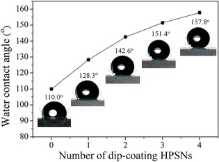
Dependence of the water contact angle on the cycle number of dip‐coated HPSNs on the surface of glass slides. Reprinted with permission from Ref. 111. Copyright 2016 Royal Society of Chemistry.
Notably, SEM imaging indicated that HPSNs were scattered on the smooth bottom layer of the SSNs in a nearly monolayer fashion (Figure 85). However, even with relatively low density of HPSNs on the surface, owing to its size and fibrous morphology (roughness), the surface showed super‐hydrophobicity. This was attributed to stabilization of liquid droplets on the rough surface in the Cassie–Baxter state resulting from the formation of many microscopic air droplets as a result of the dendritic nature of the HPSNs (Figure 86). These results indicated the potential of DFNS materials as functional coating materials for various industrial applications.111
Figure 85.
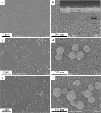
SEM images of the a, b) 3‐dip SSN coatings, c, d) 3‐dip SSN+2‐dip HPSN coating, and e, f) 3‐dip SSN+4‐dip HPSN coating after calcination and hydrophobic modification. The inset in panel b is the corresponding cross‐sectional image. Reprinted with permission from Ref. 111. Copyright 2016 Royal Society of Chemistry.
Figure 86.
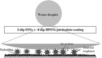
Proposed illustration of a water drop on the surface of a treated glass slide, according to the Cassie–Baxter wetting state. Reprinted with permission from Ref. 111. Copyright 2016 Royal Society of Chemistry.
10.2. Bioimaging using fluorescent DFNS coated with quantum dots
Quantum dots (QDs) such as cadmium telluride (CdTe), owing to their unique size‐sensitive optoelectronic properties, are used in a range of applications. However, as a result of their photo‐ and colloidal stability issues, as well as their toxicity, their real applications are somewhat restricted. Zhang et al. used DFNS to stabilize CdTe to improve its stability and cytotoxicity.112 DFNS was first functionalized with APTS to produce mSiO2‐NH2, which was then loaded with CdTe by using electrostatic attraction between the positively charged surface and the negatively charged CdTe. A solid silica shell (with varied thickness) was then formed over it by using Stöber's method to improve the stability (Figure 87). STEM analysis indicated the dendritic fibrous nature of mSiO2@CdTe@SiO2, whereas EDS elemental mapping indicated a uniform distribution of CdTe on the fibers of DFNS silica (Figure 88). These materials showed improved QD stability, low toxicity, and strong fluorescence (used for bioimaging).
Figure 87.
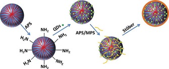
Synthesis of mSiO2@CdTe@SiO2 fluorescent nanoparticles.112 APS=(3‐aminopropyl)triethoxysilane, MPS=(3‐mercaptopropyl)trimethoxysilane.
Figure 88.
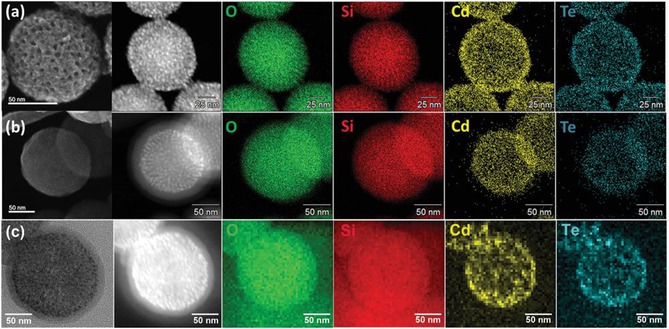
STEM images and EDS elemental mapping of a) mSiO2@CdTe, b) mSiO2@CdTe@SiO2, and c) an ultramicrotomed mSiO2@CdTe@SiO2 slice. Reprinted with permission from Ref. 112. Copyright 2016 Wiley‐VCH.
10.3. Extraction and detection of pollutants using DFNS for environmental remediation
The removal of pollutants, such as toxic metal ions, phosphorus, and polyaromatic hydrocarbons, from water bodies is a serious environmental concern. Huang et al. used lanthanum (La)‐doped DFNS for the removal of phosphorus,113 and the sample was prepared by the postsynthetic loading of lanthanum nitrate hexahydrate in DFNS by using the ethanol evaporation method. DFNS/La with a La/Si molar ratio of 0.1 showed the best performance, far better than the performance of similar conventional materials, which was indicative of the role of the fibrous morphology and the varied pore sizes (fiber channels) in minimizing diffusion issues and improving phosphors adsorption. Similarly, Xie et al. functionalized DFNS with cyano groups, which upon conversion into amidoxime groups were used for the adsorption of various ions such as Fe3+, Cu2+, and Pb2+.114 They observed the selective adsorption of Pb2+ with a maximum adsorption capacity of 284 mg g−1. Not only adsorption but also desorption of Pb2+ was efficient and complete within 1 h.
Yan and co‐workers used multifunctional and magnetic DFNS for both the removal of Zn2+ ions and their detection (sensing probe).115 The development of selective and sensitive sensors/probes for detecting metal ions is key for a green environment, and this work showed exceptional use of DFNS to achieve two‐in‐one activity involving the sensing and selective removal of Zn2+ ions. Magnetic DFNS was prepared by using Fe3O4 seeds, followed by functionalization with 8‐chloroacetylaminoquinoline (AQ‐Cl) (Figure 89). AQ‐Fe3O4@SiO2@DFNS recognized Zn2+ with excellent selectively (over a variety of other competing metal ions) with a fluorescence emission response detection limit of 1.08×10⁻⁷ m. In addition to sensing, it showed a good adsorption capacity of 157 mg g−1. The fibrous morphology of DFNS in combination with the organic AQ‐Cl receptor seems to be a good alternative for the development of probe‐cum‐adsorbents for toxic metal ions.
Figure 89.
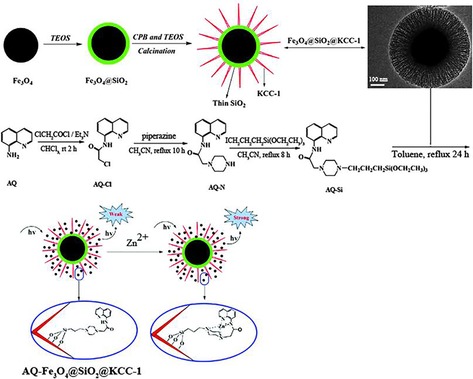
Schematic for the synthesis of AQ‐Fe3O4@SiO2@DFNS. Reprinted with permission from Ref. 115. Copyright 2015 Royal Society of Chemistry.
Yan's group extended this strategy to the sensing and adsorption of Hg2+ ions.116 DFNS was functionalized with a rhodamine‐based receptor (RB). RB‐DFNS showed an increase in the Hg2+‐induced absorption band intensity, fluorescence, and even a color change from colorless to purple, which allowed for naked‐eye detection. The material adsorbed a high concentration of mercury ions (115.47 mg g−1), and the authors also showed its use in live‐cell imaging. RB‐DFNS seems to be a three‐in‐one material for sensing, adsorption, and live imaging.
In addition to metal ions, DFNS‐based materials were also used to remove polyaromatic hydrocarbon pollutants from the environment. Yang et al. prepared carbon‐doped DFNS using cetyltrimethylammonium chloride (CTAC) as a template and carbon precursor by simply tuning the thermal treatment conditions during in situ carbonization.117 They were able to produce fibrous silica with various loadings of carbon (i.e., 0, 1, and 6 wt %). Pretreatment using sulfuric acid helped to increase the carbon content. These materials showed an improved adsorption of anthracene with rapid kinetics.
10.4. Sensing and quantification of pollutants using a DFNS‐based surface plasmon resonance technique
Quantification of very low concentrations of arsenic (a pollutant with serious health concerns) by using DFNS was reported by Hong and co‐workers.118 In this exceptional work, they monitored changes in the surface plasmon resonance (SPR) reflectance (ΔR) near the SPR angle. First, a gold thin film (precleaned with piranha solution) was treated with a 1 nm ethanol solution of 3‐mercaptoundecanonic acid (MUA) to form a self‐assembled monolayer (SAM) on the gold film. Then, the carboxylic group of MUA was converted into a reactive ester group by reaction with N‐hydroxysuccinimide (NHS) and N‐(3‐dimethylaminopropyl)‐N‐ethylcarbodiimide (EDC). Alternatively, DFNS was functionalized by an amine by using APTS and was then loaded on the above‐functionalized gold film by carbodiimide coupling. The kinetics of this coupling were fast (10 min) owing to the strong affinity between the functionalized gold surface and DFNS. SEM images indicated a uniform distribution of DFNS on the gold surface in a near monolayer with some vacant sites.
This DFNS‐loaded gold film was used to detect changes in the SPR angle upon treatment with AsIII. To induce electrostatic attraction and to enhance the binding affinity of AsIII, DFNS‐NH2 was converted into DFNS‐NH3 + by treatment with HCl. As a result of the radially oriented dendritic fibrous nature of DFNS, analytes (e.g., H2AsO4 −) had easy access to the receptors (amine sites) within the fibrous channels, which thus increased the sensitivity and lowered the detection limit concentration (compared to conventional silica or flat surfaces) (Figure 90). Upon exposure of the sensor to an Na2HAsO4 aqueous solution, AsIII complexed with the surface amines of the silica nanospheres through electrostatic interactions (Figure 90 a), which changed the SPR profile significantly (Figure 90 b). Specifically, after exposure to a 400 nm AsIII solution for 1 h, a change in the SPR angle of approximately 0.4° was observed. This change was attributed to the change in the local refractive index at the interface of the sensor surface. The vacant sites in the DFNS monolayer on the gold film did not affect the sensing performance, as SPR signals were obtained by averaging a light scanning area of approximately 1 mm2. The limit of detection was 1.0 nm, and a linear response was observed for AsIII concentrations in the range of 10 to 600 nm on a semilog scale. In terms of selectivity, the sensor showed a high selectivity for AsIII ions over other anions, including H2PO4 −, SO4 2−, NO3 −, and Cl−. The authors also demonstrated its use in a real‐world application, that is, in the quantification of arsenic in their laboratory tap water. These exciting results indicated the use of the unique fibrous morphology in the development of a very unique SPR‐based sensor.118
Figure 90.
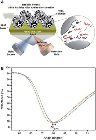
a) Schematic for the detection of AsIII by using a DFNS‐loaded gold thin film by using the SPR technique and the b) SPR spectra before (orange line) and after (blue line) exposure of the DFNS‐loaded gold film to an AsIII solution (400 nm) under flow conditions for 1 h. Reprinted with permission from Ref. 118. Copyright 2014 Royal Society of Chemistry.
10.5. Enzyme‐linked immunosorbent assay using DFNS
An ultrasensitive enzyme‐linked immunosorbent assay (ELISA+) with a 2000‐fold enhancement in detection sensitivity was developed by Yu and co‐workers by using DFNS (renamed DMSNs).119 In this exciting work, they immobilized the horseradish peroxidase (HRP) enzyme by treating it with aldehyde‐functionalized DMSNs through a Schiff base linkage to produce three different pore diameters: 6.9 nm (DMSN‐1), 14.9 nm (DMSN‐2), and 34.2 nm (DMSN‐3). In conventional ELISA, analytes are selectively captured by the first antibody, followed by the second antibody, and are then conjugated with the enzyme (such as HRP), which upon the addition of a substrate, such as 3,3′,5,5′‐tetramethylbenzidine (TMB), generates a color change, the intensity of which allows the quantification of the analyte (Figure 91 a). Conventional ELISA does not work below its limit of detection (LOD), whereas early‐stage disease diagnosis requires the detection of analyte in trace amounts. This significant challenge was solved by Yu and co‐workers by using DFNS (DMSNs) (Figure 91 b).119
Figure 91.
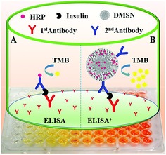
Comparison between a) conventional ELISA and b) ELISA+ with the use of DMSN. Reprinted with permission from Ref. 119. Copyright 2016 Royal Society of Chemistry.
DMSN having a surface area of 484 m2 g−1 and a pore volume of 1.39 cm3 g−1 with an average pore size of 14.5 nm showed very high loadings of the HRP enzyme. Additionally, the dendritic fibrous channels increased the accessibility of the loaded enzyme for interaction with molecules/analytes, which in turn caused a 2000‐fold enhancement in detection sensitivity of the insulin in serum compared to a commercial ELISA kit (Figure 92).
Figure 92.
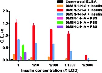
Optical density (OD) values of commercial ELISA and ELISA+ at different insulin concentrations. The numbers (1, 1:10, 1:100, 1:1000, and 1:2000) on the x axis represent the insulin dilution times of LOD (detection limit of the commercial ELISA kit). Reprinted with permission from Ref. 119. Copyright 2016 Royal Society of Chemistry.
10.6. High‐performance liquid chromatography using DFNS‐like silica
Owing to the fibrous nature of DFNS, it can be used as a stationary phase in chromatography. Not exactly DFNS, but solid silica spheres with DFNS‐like fibrous shells (Figure 93) were used in high‐performance liquid chromatography (HPLC).120 The authors were able to tune the shell thickness from 13 to 67 nm. After modification of these solid core–fibrous shell silica nanoparticles (0.5 to 3 μm in size) with C18 alkane molecules, they showed excellent performance for the separation of naphthalene, peptides (Figure 94), and proteins with very low back pressure.
Figure 93.
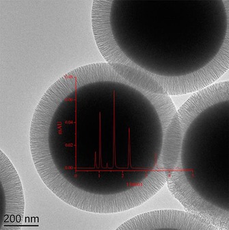
TEM image of solid core–fibrous shell silica nanoparticles. Reprinted with permission from Ref. 120. Copyright 2015 American Chemical Society.
Figure 94.
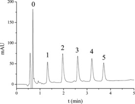
HPLC separation of a mixture of five peptides with a back pressure of 21.7 MPa. Peaks: 0, solvent; 1, R‐V‐Y‐H‐P‐I (883.1 Da); 2, R‐V‐Y‐V‐H‐P‐F (917.1 Da); 3, A‐P‐G‐D‐R‐I‐Y‐V‐H‐P‐F (1271.4 Da); 4, D‐R‐V‐Y‐VH‐P‐F‐H‐L (1282.5 Da); 5, D‐R‐V‐Y‐I‐H‐P‐F‐H‐L (1296.5 Da). Reprinted with permission from Ref. 120. Copyright 2015 American Chemical Society.
10.7. Energy storage using DFNS‐based supercapacitors
The development of next‐generation supercapacitors for energy storage requires active electrode materials with tunable pore sizes, pore volumes, and surface areas as well as surface morphologies. High surface area carbon spheres with DFNS‐like fibrous morphology were prepared by Huang and co‐workers, and they showed extraordinary performance in supercapacitor applications.121 They used amine‐functionalized DFNS as a hard template and glucose as a carbon precursor, which reacted with the surface amine groups of DFNS under hydrothermal conditions. This was then carbonized at 800 °C for 2 h under an argon atmosphere, which was followed by silica etching (using HF) to generate fibrous carbon spheres (Figure 95), named hydrangea‐like multiscale carbon hollow submicron spheres (HCSSg). HCSSg with different glucose loadings (i.e., 0.75, 1, 1.5, and 2 g per 0.5 g of DFNS‐NH2) were prepared.
Figure 95.
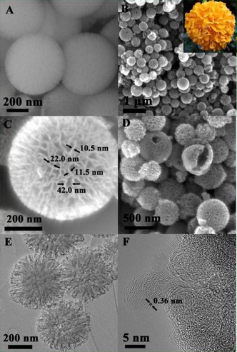
SEM images of a) DFNS‐NH2 (FSS) and b–d) HCCSg1.0 and e, f) TEM images of HCCSg1.0. Reprinted with permission from Ref. 121. Copyright 2015 Elsevier B.V.
Cyclic voltammetry (CV) measurements at various scan rates showed a typical quasirectangular shape, which was preserved even at a very high scan rate of 500 mV s−1. These results indicated ideal capacitive behavior and rapid charge propagation ability of the material. HCSSg1.0 showed the highest gravimetric capacitance of 230 F g−1 at a scan rate of 5 mV s−1 (Figure 96). Furthermore, a galvanostatic charge/discharge (GCD) study indicated no significant voltage drop resulting from internal resistance (Figure 97). HCSSg1.0 exhibited high gravimetric capacitance (386 F g−1 at 0.2 A g−1) as well as excellent volumetric capacitance, an important parameter for compact and portable energy‐storage devices (335 F cm−3 at 0.2 A g−1 and 246 F cm−3 at 0.5 A g−1) as a result of its high bulk density (0.87 g cm−3). It also showed good rate capability (171 F g−1 at 15 A g−1) as well as good energy and power density. The author claimed that these were the best numbers among those of reported previously for carbon materials, which was indicative of the role of the fibrous morphology of DFNS for advanced supercapacitor development.121
Figure 96.
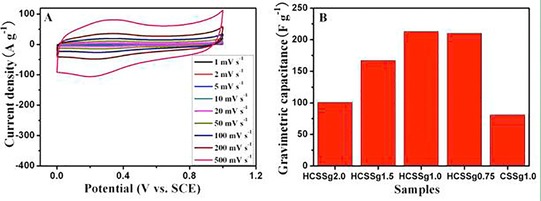
a) CV curves of the HCSSg1.0 electrode and b) gravimetric specific capacitance calculated based on the CV curves at a scan rate of 5 mV s−1. Reprinted with permission from Ref. 121. Copyright 2015 Elsevier B.V.
Figure 97.
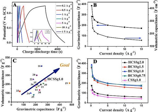
a) GCD curves of the HCSSg1.0 electrode at different current densities, b) gravimetric and volumetric specific capacitances versus current densities for the HCSSg1.0 electrode, c) comparison of the volumetric and gravimetric capacitance of HCSSg1.0 calculated on the basis of the discharge curve at a density of 0.5 A g−1 with other reported carbon electrodes, and d) gravimetric capacitance calculated from the corresponding discharge curves. Reprinted with permission from Ref. 121. Copyright 2015 Elsevier B.V.
11. Conclusions and Future Perspective
Dendritic fibrous nanosilica (DFNS) has attracted a great deal of attention in a large number of scientific disciplines such as catalysis, solar‐energy harvesting (e.g., photocatalysis, solar cells, etc.), energy storage, self‐cleaning antireflective coatings, surface plasmon resonance (SPR)‐based ultrasensitive sensors, CO2 capture, and biomedical applications (e.g., drug delivery, protein and gene delivery, bioimaging, photothermal ablation, Ayurvedic and radiotherapeutics drug delivery, etc.). As discussed in this Review, the unique fibrous morphology of the DFNS family of materials bestows them with several important properties that have been brilliantly exploited for use in a range of applications. The fibers of DFNS were functionalized with a range of organic groups, ionic liquids, organometallic complexes, polymers, peptides, enzymes, DNA, and genes. They were also loaded with metal nanoparticles, bimetallic nanoparticles, and even with single atoms of metals, quantum dots, and metal oxides and hydroxides. They were also used as hard templates for the synthesis of high surface area carbon with a fibrous morphology. DFNS‐based zeolites were also synthesized with unique activities.
DFNS has provided a means to load large amounts of active sites with exceptionally high accessibility compared to conventional mesoporous silica materials. Additionally, owing to the radially oriented pores (channels), the size of which increases from the center of the sphere to its outer surface, reactants are able to access the active sites within the channels easily, and this increases their interaction with catalytic sites. This had led to a multifold increase in their catalytic activity. The fibrous morphology of DFNS in combination with various functionalization groups (e.g., amines, mercapto, polyamines, etc.) as chelators was found to minimize active‐site leaching. It also restricted the agglomeration and sintering of the active sites, such as metal nanoparticles and even pseudo‐single atoms of metals. This increased the stability of the nanocatalysts, which is a critical issue for conventional nanocatalysts. DFNS‐based zeolites allowed for the development of solid acid catalysts and unique pickering interfacial catalysis with exceptional performance. Nitridation of DFNS allowed for the development of highly active base catalysts. DFNS was also made magnetic, which made catalyst separation possible by using an external magnet.
DFNS was cleverly used to develop novel photocatalysts by coating with graphitic carbon nitride and TiO2. The fibrous morphology of DFNS not only facilitated mass transfer and improved accessibility (as in thermal catalysis) but also facilitated the formation of a uniform conformal coating and a high loading of semiconductors and guest molecules without a significant reduction in surface area. Notably, owing to the fibrous structure of the material, the light‐harvesting properties of the catalyst were enhanced as a result of multiple scattering effects and the reflection of a large amount of incident light. Additionally, most of the excitons were on the surface, which hence led to exceptional catalytic performances (e.g., for dye degradation, water splitting, etc.). DFNS was also used to improve the performance of dye‐sensitized solar cells (DSSCs) by using TiO2‐coated DFNS as a light scatterer in the DSSCs to multiply light‐scattering events at the abundant particle (fiber)–air interfaces. This resulted in a remarkable improvement in the short‐circuit current, whereas the open‐circuit voltage and fill factor remained unchanged. In addition to energy harvesting, DFNS‐coated carbon spheres were also used for energy storage by using supercapacitors.
Functionalized DFNS, such as DFNS‐amines and DFNS‐oxynitrides, were successfully used to develop efficient CO2 sorbents, and these could contribute to tackling the potentially dangerous issue of climate change. The fibrous nature not only allowed for an increased loading of amine groups with moderate loss of surface area (compared to MCM‐41 and SBA‐15), but it also improved the CO2 capture capacity, kinetics of capture, and, importantly, the stability of the sorbent. Functionalized DFNS was also used to remove pollutants such as toxic metal ions, phosphorus, and polyaromatic hydrocarbons from water bodies, which is a serious environmental concern.
The use of DFNS in biomedical applications was thoroughly explored. It was efficiently used to deliver various anticancer drugs, and even the delivery of the Ayurvedic drug curcumin, DNA, genes, and antimicrobial enzymes was achieved. Notably, the codelivery of a drug and a nucleic acid as well as the simultaneous delivery of chemo‐ and radiotherapeutics was possible. In addition, a number of auxiliary functions were integrated into DFNS, such as stimuli responsiveness (light to thermal), fluorescence, radioactivity, antireflectance, and superhydrophobicity. This allows their application in areas such as photothermal ablation therapy, real‐time bioimaging, and self‐cleaning coatings.
The sensing and quantification of pollutants by using a DFNS‐based SPR technique was a unique application of this material. Another unique application of DFNS was the development of an ultrasensitive enzyme‐linked immunosorbent assay with a detection sensitivity that was 2000‐fold higher than that of a commercial ELISA. The fibrous nature of silica was also used to develop a stationary phase for chromatography.
Notwithstanding the rapid development of fibrous silica nanospheres for various applications, these nanospheres have huge potential for future development:
Synthesis: In the last few years, several protocols for the synthesis of the DFNS family of nanomaterials were developed; however, an efficient protocol for their synthesis with easy‐to‐control reaction parameters to tune the size and textural properties of DFNS will for its efficient use in various other fields. Synthesis under flow conditions could make the process more economical and up‐scalable
Formation mechanism: Although few works have systemically investigated the mechanism of formation of DFNS and achieved good insight, its mechanism of formation is not yet clearly understood and remains unresolved owing to the very complex interplay between surfactant, co‐surfactant, solvent, urea, and other reaction parameters. Future work is still required to understand fundamentally and unambiguously the mechanism of formation. This understanding may then allow the use of the DFNS protocol for the synthesis of materials other than silica, which is not possible to date
Applications: Despite the significant amount of reports in a short period of time, the application of DFNS is limited and seems to be in the early stage of development. Significant advances can be foreseen in several disciplines, including heterogeneous catalysis and photocatalysis, CO2 capture and conversion, sensing, photonics, coatings, chromatography, biomedical, and so on
Catalysis: A systematic study to develop a correlation between fiber density, pore size (and their distribution), and catalyst performance (i.e., activity, selectivity, and stability) will allow the development of new nanocatalysts using the “catalyst by design” concept. Confinement within the fibers is also unexplored
Photocatalysis: In the case of photocatalysis, a more detailed study is needed to understand the improved light‐harvesting properties of this material. Charge migration and charge recombination is also not completely understood. The use of various spectroscopic techniques could enable a better understanding
Biomedical: Drug delivery of a range of drug molecules, even those of large size, could be explored. The combination of various stimuli will enable the development of “stimuli‐responsive” nanocarriers. Drugs with poor solubility in water could possibly be loaded and delivered to cancerous cells by using KCC‐1 with various fiber densities (pore sizes)
Analytical: Sensing and detection can be extended to single‐particle imaging with multifold improvement in sensitivity by using DFNS. Selective ion extraction by controlling the fiber channel distance could be another possibility
Commercialization: Although DFNS has been gifted with excellent textural, physical, and chemical properties and shows exceptional results in various applications, the evolution of DFNS from fundamental research studies in the laboratory to being used in industry will depend on collaborations between academic researchers and industry. Testing of DFNS ‐based materials for various applications on the pilot‐plant scale in industry could be a good approach to achieve the practical relevance of DFNS
Thus, remarkable advances in the synthesis and applications of DFNS have been achieved, and DFNS seems to have demonstrated great potential as a superior alternative to conventional silica materials such as Stöber silica, MSN, MCM‐41, and SBA‐15, among others. The low cost, high activity, and pronounced stability of numerous dendritic fibrous nanosilica‐based materials support our argument that this class of materials will find practical use for a range of applications, from catalysis to gas capture, from energy harvesting and storage to drug delivery, from analytical chemistry to environmental remediation and more.
Conflict of interest
The authors declare no conflict of interest.
Biographical Information
Dr. Vivek Polshettiwar, after obtaining his Ph.D. degree in 2005, worked as a postdoctoral researcher in France and USA for a few years, before he started his own independent group at KAUST. In 2013, he moved to TIFR, Mumbai, as a reader, and his group there worked on the development of novel nanomaterials for catalysis and CO2 capture conversion. He has published nearly 90 articles with an h‐index of 47 and has around 8000 citations in reputed journals. He was the recipient of the prestigious ORISE Research Fellowship at US‐EPA and several other esteemed postdoctoral fellowships. He was named one of the Top‐25 cited authors in 2011 by Tetrahedron and received the Young Scientist Award at DSL‐2012. He also received the Asian Rising Star lectureship at 15th Asian Chemical Congress (ACC), Singapore (2013), from Nobel Laureate Professor Ei‐ichi Negish. In 2015, he was admitted as a Fellow of the Royal Society of Chemistry (RSC), United Kingdom, and was also recognized as one of the 175 Faces of Chemistry by the RSC. Recently, he was awarded the Bronze medal by CRSI, India.

Biographical Information
Mr. Ayan Maity did his bachelor studies at Presidency University, Kolkata, and joined the Tata Institute of Fundamental Research for an Integrated Ph.D. degree in 2014, in Prof. Polshettiwar's Nanocat group. His interests include the study of the fundamental aspects of nanomaterials chemistry and synthesis of novel materials with applications in catalysis and CO2 capture conversion. He has attended several international conferences, including the DAE‐BRNS Interdisciplinary Symposium on Materials Chemistry in BARC and the 28th Annual General Meeting of the Materials Research Society of India (MRSI), in IIT Mumbai. He received best poster awards at both conferences.

Acknowledgements
We would like to thank the Department of Atomic Energy (DAE), Government of India, for funding. V.P. also thanks his current and past group members (students and postdocs) who made important contributions to the discovery and development of DFNS (KCC‐1), especially Mr. Baljeet Singh, Mr. Rustam Singh, Mr. Mahak Dhiman, Mr. Amitava Acharjya, Mr. Amit Mishra, Mr. Krishnakant Vishvakarma, Dr. Farheen Sayed, Dr. Nisha Bayal, Dr. Simanto Kundu, Dr. Aziz Fihri, Dr. Pradeep Sarawade, Dr. Mohamed Bouhrara, Dr. Raed Rahal, and Dr. Leena George.
A. Maity, V. Polshettiwar, ChemSusChem 2017, 10, 3866.
References
- 1. Davis M. E., Nature 2002, 417, 813–821. [DOI] [PubMed] [Google Scholar]
- 2. Prieto G., Tüysüz H., Duyckaerts N., Knossalla J., Wang G.-H., Schüth F., Chem. Rev. 2016, 116, 14056–14119. [DOI] [PubMed] [Google Scholar]
- 3. Catalysis: From Principles to Applications (Eds.: M. Beller, A. Renken, R. A. van Santen), Wiley-VCH, Weinheim, 2012. [Google Scholar]
- 4. Catalysis: Concepts and Green Applications (Ed.: G. Rothenberg), Wiley-VCH, Weinheim, 2008. [Google Scholar]
- 5. Nanocatalysis: Synthesis and Applications (Eds.: V. Polshettiwar, T. Asefa), Wiley, Hoboken, NJ, 2013. [Google Scholar]
- 6.
- 6a. Stöber W., Fink A., Bohn E., J. Colloid Interface Sci. 1968, 26, 62–69; [Google Scholar]
- 6b. Li S., Wan Q., Qin Z., Fu Y., Gu Y., Langmuir 2015, 31, 824–832. [DOI] [PubMed] [Google Scholar]
- 7.
- 7a. Kresge C. T., Leonowicz M. E., Roth W. J., Vartuli J. C., Beck J. S., Nature 1992, 359, 710–712; [Google Scholar]
- 7b. Gusev V. Y., Feng X., Bu Z., Haller G. L., O'Brien J. A., J. Phys. Chem. 1996, 100, 1985–1988; [Google Scholar]
- 7c. Carniato F., Bisio C., Paul G., Gatti G., Bertinetti L., Coluccia S., Marchese L., J. Mater. Chem. 2010, 20, 5504–5509; [Google Scholar]
- 7d. Kim M. J., Kwak H. J., Shine J., Ryoo R., J. Phys. Chem. 1995, 99, 16742–16747. [Google Scholar]
- 8.
- 8a. Zhao D., Feng J., Huo Q., Melosh N., Fredrickson G. H., Chmelka B. F., Stucky G. D., Science 1998, 279, 548–552; [DOI] [PubMed] [Google Scholar]
- 8b. Cao L., Man T., Kruk M., Chem. Mater. 2009, 21, 1144–1153; [Google Scholar]
- 8c. Hartmann M., Vinu A., Langmuir 2002, 18, 8010–8016; [Google Scholar]
- 8d. Celer B. E., Kruk M., Zuzek Y., Jaroniec M., J. Mater. Chem. 2006, 16, 2824–2833; [Google Scholar]
- 8e. Lowe J. B., Baker R. T., J. Nanomater. 2014, 754076. [Google Scholar]
- 9. Cha J. N., Stucky G. D., Morse D. E., Deming T. J., Nature 2000, 403, 289–292. [DOI] [PubMed] [Google Scholar]
- 10. Yu C. Z., Tian B. Z., Fan J., Stucky G. D., Zhao D., J. Am. Chem. Soc. 2002, 124, 4556–4557. [DOI] [PubMed] [Google Scholar]
- 11.
- 11a. Che S., Garcia-Bennett A. E., Yokoi T., Sakamoto K., Kunieda H., Terasaki O., Tatsumi T., Nat. Mater. 2003, 2, 801–805; [DOI] [PubMed] [Google Scholar]
- 11b. Yan F., Jiang J., Tian S., Liu Z., Shi J., Li K., Chen X., Xu Y., ACS Sustainable Chem. Eng. 2016, 4, 4654–4661; [Google Scholar]
- 11c. Möller K., Bein T., Chem. Mater. 2017, 29, 371–388. [Google Scholar]
- 12. Che S., Liu Z., Ohsuna T., Sakamoto K., Terasaki O., Tatsumi T., Nature 2004, 429, 281–284. [DOI] [PubMed] [Google Scholar]
- 13. Yokoi T., Sakamoto Y., Terasaki O., Kubota Y., Okubo T., Tatsumi T., J. Am. Chem. Soc. 2006, 128, 13664–13665. [DOI] [PubMed] [Google Scholar]
- 14. Gao C., Sakamoto Y., Sakamoto K., Terasaki O., Che S., Angew. Chem. Int. Ed. 2006, 45, 4295–4298; [DOI] [PubMed] [Google Scholar]; Angew. Chem. 2006, 118, 4401–4404. [Google Scholar]
- 15. Bao Y., Shi C., Wang T., Li X., Ma J., Microporous Mesoporous Mater. 2016, 227, 121–136. [Google Scholar]
- 16. Du X., Qiao S. Z., Small 2015, 11, 392–413. [DOI] [PubMed] [Google Scholar]
- 17. Polshettiwar V., Cha D., Zhang X., Basset J. M., Angew. Chem. Int. Ed. 2010, 49, 9652–9656; [DOI] [PubMed] [Google Scholar]; Angew. Chem. 2010, 122, 9846–9850. [Google Scholar]
- 18. Polshettiwar V., Basset J. M., US20110253643, 2010.
- 19. Bayal N., Singh B., Singh R., Polshettiwar V., Sci. Rep. 2016, 6, 24888. [DOI] [PMC free article] [PubMed] [Google Scholar]
- 20. Moon D.-S., Lee J.-K., Langmuir 2012, 28, 12341–12347. [DOI] [PubMed] [Google Scholar]
- 21. Moon D.-S., Lee J.-K., Langmuir 2014, 30, 15574–15580. [DOI] [PubMed] [Google Scholar]
- 22. Febriyanti E., Suendo V., Mukti R. R., Prasetyo A., Arifin A. F., Akbar M. A., Triwahyono S., Marsih I. N., Langmuir 2016, 32, 5802–5811. [DOI] [PubMed] [Google Scholar]
- 23. Zhang K., Xu L.-L., Jiang J.-G., Calin N., Lam K.-F., Zhang S.-J., Wu H.-H., Wu G.-D., Albela B., Bonneviot L., Wu P., J. Am. Chem. Soc. 2013, 135, 2427–2430. [DOI] [PubMed] [Google Scholar]
- 24. Yu Y.-J., Xing J.-L., Pang J.-L., Jiang S.-H., Lam K.-F., Yang T.-Q., Xue Q.-S., Zhang K., Wu P., ACS Appl. Mater. Interfaces 2014, 6, 22655–22665. [DOI] [PubMed] [Google Scholar]
- 25. Yang H., Liao S., Huang C., Du L., Chen P., Huang P., Fu Z., Li Y., Appl. Surf. Sci. 2014, 314, 7–14. [Google Scholar]
- 26. Shen D., Yang J., Li X., Zhou L., Zhang R., Li W., Chen L., Wang R., Zhang F., Zhao D., Nano Lett. 2014, 14, 923–932. [DOI] [PubMed] [Google Scholar]
- 27. Du X., Li X., Huang H., He J., Zhang X., Nanoscale 2015, 7, 6173–6184. [DOI] [PubMed] [Google Scholar]
- 28. Yamada H., Ujiie H., Urata C., Yamamoto E., Yamauchi Y., Kuroda K., Nanoscale 2015, 7, 19557–19567. [DOI] [PubMed] [Google Scholar]
- 29. Gustafsson H., Isaksson S., Altskär A., Holmberg K., J. Colloid Interface Sci. 2016, 467, 253–260. [DOI] [PubMed] [Google Scholar]
- 30. Nandiyanto A. B. D., Kim S.-G., Iskandar F., Okuyama K., Microporous Mesoporous Mater. 2009, 120, 447–453. [Google Scholar]
- 31. Fihri A., Bouhrara M., Cha D., Saih Y., Patil U., Polshettiwar V., ACS Catal. 2012, 2, 1425–1431. [Google Scholar]
- 32. Fihri A., Bouhrara M., Cha D., Polshettiwar V., ChemSusChem 2012, 5, 85–89. [DOI] [PubMed] [Google Scholar]
- 33. Qureshi Z. S., Sarawade P. B., Albert M., D'Elia V., Hedhili M. N., Köhler K., Basset J.-M., ChemCatChem 2015, 7, 635–642. [Google Scholar]
- 34. Le X., Dong Z., Li X., Zhang W., Le M., Ma J., Catal. Commun. 2015, 59, 21–25. [Google Scholar]
- 35. Liu Y., Dong Z., Li X., Le X., Zhang W., Ma J., RSC Adv. 2015, 5, 20716–20723. [Google Scholar]
- 36. Shen D., Chen L., Yang J., Zhang R., Wei Y., Li X., Li W., Sun Z., Zhu H., Abdullah A. M., Al-Enizi A., Elzatahry A. A., Zhang F., Zhao D., ACS Appl. Mater. Interfaces 2015, 7, 17450–17459. [DOI] [PubMed] [Google Scholar]
- 37. Dhiman M., Chalke B., Polshettiwar V., ACS Sustainable Chem. Eng. 2015, 3, 3224–3230. [Google Scholar]
- 38. Gautam P., Dhiman M., Polshettiwar V., Bhanage B. M., Green Chem. 2016, 18, 5890–5899. [Google Scholar]
- 39. Kundu P. K., Dhiman M., Modak A., Chowdhury A., Polshettiwar V., Maiti D., ChemPlusChem 2016, 81, 1142–1146. [DOI] [PubMed] [Google Scholar]
- 40. Sadeghzadeh S. M., Catal. Sci. Technol. 2016, 6, 1435–1441. [Google Scholar]
- 41. Ying J., Peng H., Xu X., Wang R., Yu F., Sun Q., Liu W., Gao Z., Wang X., Catal. Sci. Technol. 2016, 6, 5405–5414. [Google Scholar]
- 42. Dong Z., Le X., Li X., Zhang W., Dong C., Ma J., Appl. Catal. B 2014, 158–159, 129–135. [Google Scholar]
- 43. Sun Z., Cui G., Li H., Tian Y., Yan S., Colloids Surf. A 2016, 489, 142–153. [Google Scholar]
- 44. Ouyang M., Wang Y., Zhang J., Zhao Y., Wang S., Ma X., RSC Adv. 2016, 6, 12788–12791. [Google Scholar]
- 45. Qureshi Z. S., Sarawade P. B., Hussain I., Zhu H., Al-Johani H., Anjum D. H., Hedhili M. N., Maity N., D'Elia V., Basset J.-M., ChemCatChem 2016, 8, 1671–1678. [Google Scholar]
- 46. Johnston P., Carthey N., Hutchings G. J., J. Am. Chem. Soc. 2015, 137, 14548–14557. [DOI] [PubMed] [Google Scholar]
- 47. Yang X.-F., Wang A., Qiao B., Li J., Liu J., Zhang T., Acc. Chem. Res. 2013, 46, 1740–1748. [DOI] [PubMed] [Google Scholar]
- 48. Dhiman M., Polshettiwar V., J. Mater. Chem. A 2016, 4, 12416–12424. [Google Scholar]
- 49. Dhiman M., Chalke B., Polshettiwar V., J. Mater. Chem. A 2017, 5, 1935–1940. [Google Scholar]
- 50. Jung D., Kim Y.-J., Lee J.-K., Bull. Korean Chem. Soc. 2016, 37, 386–389. [Google Scholar]
- 51. Afzal S., Quan X., Chen S., Wang J., Muhammad D., J. Hazard. Mater. 2016, 318, 308–318. [DOI] [PubMed] [Google Scholar]
- 52. Tian Y., Liu Y., Sun Z., Li H., Cui G., Yan S., RSC Adv. 2015, 5, 106068–106076. [Google Scholar]
- 53. Firmansyah M. L., Jalil A. A., Triwahyono S., Hamdan H., Salleh M. M., Ahmad W. F. W., Kadja G. T. M., Catal. Sci. Technol. 2016, 6, 5178–5182. [Google Scholar]
- 54. Teh L. P., Triwahyonoa S., Jalil A. A., Firmansyah M. L., Mamat C. R., Majid Z. A., Appl. Catal. A 2016, 523, 200–208. [Google Scholar]
- 55. Choi Y., Yun Y. S., Park H., Park D. S., Yun D., Yi J., Chem. Commun. 2014, 50, 7652–7655. [DOI] [PubMed] [Google Scholar]
- 56. Lyu L., Zhang L., Hu C., Yanga M., J. Mater. Chem. A 2016, 4, 8610–8619. [Google Scholar]
- 57. Peng H.-G., Xu L., Wu H., Zhang K., Wu P., Chem. Commun. 2013, 49, 2709–2711. [DOI] [PubMed] [Google Scholar]
- 58. Peng H., Wang D., Xu L., Wu P., Chin. J. Catal. 2013, 34, 2057–2065. [Google Scholar]
- 59. Yang Y., Zhou W.-J., Liebens A., Clacens J.-M., Pera-Titus M., Wu P., J. Phys. Chem. C 2015, 119, 25377–25384. [Google Scholar]
- 60. Asefa T., Kruk M., Coombs N., Grondey H., MacLachlan M. J., Jaroniec M., Ozin G. A., J. Am. Chem. Soc. 2003, 125, 11662–11673. [DOI] [PubMed] [Google Scholar]
- 61. Sugino K., Oya N., Yoshie N., Ogura M. A., J. Am. Chem. Soc. 2011, 133, 20030–20032. [DOI] [PubMed] [Google Scholar]
- 62. Bouhrara M., Ranga C., Fihri A., Shaikh R., Sarawade P., Emwas A., Hedhili M. N., Polshettiwar V., ACS Sustainable Chem. Eng. 2013, 1, 1192–1199. [Google Scholar]
- 63. Lilly Thankamony A. S., Lion C., Pourpoint F., Singh B., Linde A. J. P., Carnevale D., Bodenhausen G., Vezin H., Lafon O., Polshettiwar V., Angew. Chem. Int. Ed. 2015, 54, 2190–2193; [DOI] [PubMed] [Google Scholar]; Angew. Chem. 2015, 127, 2218–2221. [Google Scholar]
- 64. Singh B., Mote K. R., Gopinath C. S., Madhu P. K., Polshettiwar V., Angew. Chem. Int. Ed. 2015, 54, 5985–5989; [DOI] [PubMed] [Google Scholar]; Angew. Chem. 2015, 127, 6083–6087. [Google Scholar]
- 65. Siddiqui Z. N., Khan K., Ahmed N., Catal. Lett. 2014, 144, 623–632. [Google Scholar]
- 66. Najafi Chermahini A., Shahangi F., Dabbagh H. A., Saraji M., RSC Adv. 2016, 6, 33804–33810. [Google Scholar]
- 67. Yang H., Li S., Zhang X., Wang X., Ma J., J. Mater. Chem. A 2014, 2, 12060–12067. [Google Scholar]
- 68. Sadeghzadeh S. M., Catal. Commun. 2015, 72, 91–96. [Google Scholar]
- 69. Sadeghzadeh S. M., Microporous Mesoporous Mater. 2016, 234, 310–316. [Google Scholar]
- 70. Sadeghzadeh S. M., RSC Adv. 2016, 6, 75973–75980. [Google Scholar]
- 71. Sadeghzadeh S. M., Green Chem. 2015, 17, 3059–3066. [Google Scholar]
- 72. Zhu J., Zhao X.-J., Wang P.-C., Lu M., Chem. Lett. 2013, 42, 1505–1507. [Google Scholar]
- 73. Polshettiwar V., Thivolle-Cazat J., Taoufik M., Stoffelbach F., Norsic S., Basset J.-M., Angew. Chem. Int. Ed. 2011, 50, 2747–2751; [DOI] [PubMed] [Google Scholar]; Angew. Chem. 2011, 123, 2799–2803. [Google Scholar]
- 74. Sadeghzadeh S. M., J. Mol. Catal. A 2016, 423, 216–223. [Google Scholar]
- 75. Pang J., Zhou G., Liu R., Li T., Mater. Sci. Eng. C 2016, 59, 35–42. [DOI] [PubMed] [Google Scholar]
- 76. Zhang J., Zhang M., Yang C., Wang X., Adv. Mater. 2014, 26, 4121–4126. [DOI] [PubMed] [Google Scholar]
- 77. Singh R., Bapat R., Qin L., Feng H., Polshettiwar V., ACS Catal. 2016, 6, 2770. [Google Scholar]
- 78. Liao P. F., Wokaun A., J. Chem. Phys. 1982, 76, 751–752. [Google Scholar]
- 79. Bhunia M. K., Melissen S., Parida M. R., Sarawade P., Basset J.-M., Anjum D. H., Mohammed O. F., Sautet P., Le Bahers T., Takanabe K., Chem. Mater. 2015, 27, 8237–8247. [Google Scholar]
- 80. Ryu J., Yun J., Lee J., Lee K., Jang J., Chem. Commun. 2016, 52, 2165–2168. [DOI] [PubMed] [Google Scholar]
- 81. Kang J. S., Lim J., Rho W.-Y., Kim K., Moon D.-S., Jeong J., Jung D., Choi J.-W., Lee J.-K., Sung Y.-E., Sci. Rep. 2016, 6, 30829. [DOI] [PMC free article] [PubMed] [Google Scholar]
- 82. Sadeghzadeh S. M., RSC Adv. 2016, 6, 54236–54240. [Google Scholar]
- 83. Polshettiwar V., Luque R., Fihri A., Zhu H., Basset J. M., Chem. Rev. 2011, 111, 3036–3075. [DOI] [PubMed] [Google Scholar]
- 84. Yu K., Zhang X., Tong H., Yan X., Liu S., Mater. Lett. 2013, 106, 151–154. [Google Scholar]
- 85. Le X., Dong Z., Liu Y., Jin Z., Huy T.-D., Leb M., Ma J., J. Mater. Chem. A 2014, 2, 19696–19706. [Google Scholar]
- 86. Dong Z., Yu G., Le X., J. New Chem. 2015, 39, 8623–8629. [Google Scholar]
- 87. Le X., Dong Z., Zhang W., Li X., Ma J., J. Mol. Catal. A 2014, 395, 58–65. [Google Scholar]
- 88. Dong Z., Le X., Dong C., Zhang W., Li X., Ma J., Appl. Catal. B 2015, 162, 372–380. [Google Scholar]
- 89. Aghakhani A., Kazemi E., Kazemzad M., J. Nanopart. Res. 2015, 17, 386. [Google Scholar]
- 90. Park D. S., Yun D., Kim T. Y., Baek J., Yun Y. S., Yi J., ChemSusChem 2013, 6, 2281–2289. [DOI] [PubMed] [Google Scholar]
- 91. Samanta A., Zhao A., Shimizu G. K. H., Sarkar P., Gupta R., Ind. Eng. Chem. Res. 2012, 51, 1438–1463. [Google Scholar]
- 92. Didas S. A., Choi S., Chaikittisilp W., Jones C. W., Acc. Chem. Res. 2015, 48, 2680–2687. [DOI] [PubMed] [Google Scholar]
- 93. Singh B., Polshettiwar V., J. Mater. Chem. A 2016, 4, 7005–7019. [Google Scholar]
- 94. Patil U., Fihri A., Emwas A., Polshettiwar V., Chem. Sci. 2012, 3, 2224–2229. [Google Scholar]
- 95. Radu D. R., Pizzi N. A., Lai C.-Y., J. Mater. Sci. 2016, 51, 10632–10640. [Google Scholar]
- 96. Gai S., Yang P., Ma P., Wang D., Li C., Li X., Niu N., Lin J., J. Mater. Chem. 2011, 21, 16420–16426. [Google Scholar]
- 97. Gai S., Yang P., Ma P., Wang L., Li C., Zhanga M., Jun L., Dalton Trans. 2012, 41, 4511–4516. [DOI] [PubMed] [Google Scholar]
- 98. Du X., Shi B., Liang J., Bi J., Dai S., Qiao S. Z., Adv. Mater. 2013, 25, 5981–5985. [DOI] [PubMed] [Google Scholar]
- 99. Xiong L., Du X., Shi B., Bi J., Kleitz F., Qiao S. Z., J. Mater. Chem. B 2015, 3, 1712–1721. [DOI] [PubMed] [Google Scholar]
- 100. Munaweera I., Hong J., D'Souza A., K. J. Balkus, Jr. , J. Porous Mater. 2015, 22, 1–10. [Google Scholar]
- 101. Huang X., Tao Z., J. C. Praskavich, Jr. , Goswami A., Al-Sharab J. F., Minko T., Polshettiwar V., Asefa T., Langmuir 2014, 30, 10886–10889. [DOI] [PubMed] [Google Scholar]
- 102. Xu Y., Zhu Y., Li X., Morita H., Hanagata N., Mater. Express 2016, 6, 116–126. [Google Scholar]
- 103. Wang Y., Nor Y. A., Song H., Yang Y., Xu C., Yu M., Yu C., J. Mater. Chem. B 2016, 4, 2646–2653. [DOI] [PubMed] [Google Scholar]
- 104. Wan X., Zhuang L., She B., Deng Y., Chen D., Tang J., Mater. Sci. Eng. C 2016, 65, 323–330. [DOI] [PubMed] [Google Scholar]
- 105. Wang J., Wang Y., Liu Q., Yang L., Zhu R., Yu C., Wang S., ACS Appl. Mater. Interfaces 2016, 8, 26511–26523. [DOI] [PubMed] [Google Scholar]
- 106. Prasad S., Aggarwal B. B., “Turmeric, The Golden Spice: From Traditional Medicine To Modern Medicine” in Herbal Medicine: Biomolecular and Clinical Aspects, 2nd ed (Eds.: I. F. F. Benzie, S. Wachtel-Galor), CRC Press/Taylor & Francis, Boca Raton, FL, 2011, Ch. 13. [PubMed] [Google Scholar]
- 107. Chen R., Yang F., Xue Y., Wei X., Song L., Liu X., RSC Adv. 2016, 6, 38931–38942. [Google Scholar]
- 108. Munaweera I., Koneru B., Shi Y., Pasqua Di A. J., K. J. Balkus, Jr. , APL Mater. 2014, 2, 113315. [Google Scholar]
- 109. Munaweera I., Shi Y., Koneru B., Patel A., Dang M. H., Pasqua Di A. J., K. J. Balkus, Jr. , J. Inorg. Biochem. 2015, 153, 23–31. [DOI] [PubMed] [Google Scholar]
- 110. Atabaev T. S., Lee J. H., Lee J. J., Han D.-W., Hwang Y.-H., Kim H.-K., Hong N. H., Nanotechnology 2013, 24, 345603. [DOI] [PubMed] [Google Scholar]
- 111. Du X., Xing Y., Li X., Huang H., Geng Z., He J., Wena Y., Zhang X., RSC Adv. 2016, 6, 7864–7871. [Google Scholar]
- 112. Zhang S., Wen L., Yang J., Zeng J., Sun Q., Li Z., Zhao D., Dou S., Part. Part. Syst. Charact. 2016, 33, 261–270. [Google Scholar]
- 113. Huang W., Yu X., Tang J., Zhu Y., Zhang Y., Li D., Microporous Mesoporous Mater. 2015, 217, 225–232. [Google Scholar]
- 114. Xie Y., Wang J., Wang M., Ge X., J. Hazard. Mater. 2015, 297, 66–73. [DOI] [PubMed] [Google Scholar]
- 115. Sun Z., Li H., Guo D., Sun J., Cui G., Liu Y., Tian Y., Yan S., J. Mater. Chem. C 2015, 3, 4713–4722. [Google Scholar]
- 116. Sun Z., Guo D., Zhang L., Li H., Yang B., Yan S., J. Mater. Chem. B 2015, 3, 3201–3210. [DOI] [PubMed] [Google Scholar]
- 117. Yang J., Chen W., Shen D., Wei Y., Ran X., Teng W., Fan J., Zhang W., Zhao D., J. Mater. Chem. A 2014, 2, 11045–11048. [Google Scholar]
- 118. Choi Y., Kwak H., Hong S., Anal. Methods 2014, 6, 7054–7061. [Google Scholar]
- 119. Lei C., Xu C., Nouwens A., Yu C., J. Mater. Chem. B 2016, 4, 4975–4979. [DOI] [PubMed] [Google Scholar]
- 120. Qu Q., Min Y., Zhang L., Xu Q., Yin Y., Anal. Chem. 2015, 87, 9631–9638. [DOI] [PubMed] [Google Scholar]
- 121. Guo D., Chen X., Fang Z., He Y., Zheng C., Yang Z., Yang K., Chen Y., Huang S., Electrochim. Acta 2015, 176, 207–214. [Google Scholar]


