Abstract
We report the development of a new robotic system for direct image-guided interventions, DIGI (images acquired at the time of the intervention). The manipulator uses our previously reported Pneumatic Step Motors and is entirely made of electrically nonconductive, nonmetallic, and nonmagnetic materials. It orients a needle-guide with 2 degrees of freedom (DoF) about a fulcrum point located below the guide using an innovative Remote Center of Motion (RCM) parallelogram type mechanism. The depth of manual needle insertion is preset with a 3rd DoF, located remotely of the manipulator. Special consideration was given to the kinematic accuracy and the structural stiffness.
The manipulator includes registration markers for image-to-robot registration. Based on the images, it may guide needles, drills, or other slender instruments to a target (OD<10mm).
Comprehensive preclinical tests were performed. The manipulator is MR Safe (ASTM F2503-13). Electromagnetic compatibility (EMC) testing (IEC 60601-1-2) of the system shows that it does not conduct or radiate EM emissions. The change in the signal to noise ratio (SNR) of the MRI due to the presence and motion of the robot in the scanner is below 1%. The structural stiffness at the needle-guide is 33N/mm. The angular accuracy and precision of the manipulator itself are 0.177° and 0.077°. MRI-guided targeting accuracy and precision in-vitro were 1.71mm and 0.51mm, at an average target depth of ~38mm, with no adjustments.
The system may be suitable for DIGI where 1.07 + 0.0031 · d [mm] accuracy lateral to the needle (2D) or 1.59 + 0.0031 · d [mm] in 3D is acceptable. The system is also multi-imager compatible and could be used with other imaging modalities.
Index Terms: Robot, MR Safe, compatible, multi-imager, pneumatic, motor, remote center of motion RCM, direct IGI, DIGI
I. Introduction
Image-guided interventions (IGI) may be performed based on pre-acquired images, but using the imager at the time of the intervention to guide the procedure directly provides updated feedback and improves quality control [1, 2]. But Direct-IGI (DIGI) often require special devices such as medical robots to help the physician and improve the accuracy [3, 4]. Compatibility of robotic devices with the imaging equipment has been a challenging engineering task [5], especially with the MR environment [6, 7].
The American Society for Testing and Materials (ASTM) standard F2503-13 [8] classifies devices for the MR environment. In the United States this is mandated by the Food and Drug Administration (FDA) for clinical use of Significant Risk (SR) devices (21 CFR 812, [9]). The highest class of compatibility of devices with the MR environment is MR Safe. These are devices “that poses no known hazards resulting from exposure to any MR environment. MR Safe items are composed of materials that are electrically nonconductive, nonmetallic and nonmagnetic” [8].
Traditional active robotic components are not MR Safe. But in the last decade researchers developed and adapted several actuation and sensing components that are MR Safe. Examples of electricity-free manipulators built with a minimal amount of nonferrous metals are [10, 11]. A few MR Safe manipulators have already been built [12–16] and some meet the ASTM F2503 classification [16–18].
All current MR Safe robots are pneumatically actuated, either with purposely-built pneumatic cylinders [12], turbines [13, 19], or stepper motors [16, 18]. These were commonly powered through long hoses by pneumatic valves, either voice-coil type located outside the MRI room (ACR Zone III [20]) [18], or piezoelectric type valves located in the MR scanner room (ACR Zone IV) [16]. Position sensors have been typically built with code-wheel quadrature encoding and optical sensors, that emit an optical signal through a flexible fiber and recapture it through another fiber. The fiber sensors were not built for the MR environment, but were adapted from harsh-environment (wet, corrosive, explosive) conditions.
As described in this paper, by using several purposely made and adapted components, the development of MR Safe manipulators is no longer a daunting challenge, but actually similar in complexity to traditional robot manipulators.
Several essential advantages are also derived from being able to make “plastic” manipulators. First, a manipulator made “entirely of electrically nonconductive, nonmetallic and nonmagnetic materials may be determined to be MR Safe by providing a scientifically based rationale rather than test data” [8]. This facilitates FDA approvals and clinical translation. Second, this construction also makes the medical device more versatile, since it works within any MR environment. Third, since the MR environment imposes the highest compatibility requirements, a manipulator that is MR Safe and passes electromagnetic compatibility (EMC) tests is compatible with other imaging equipment based on the scientific rational, in other words is Multi-Imager Compatible [5]. This enables its use for various applications and even in cross-modality DIGI, for example PET-CT (positron emission tomography - computed tomography) and MRI.
The manipulator that we present includes a Remote Center of Motion (RCM) kinematic structure. Since its invention in 1995 [21], this has become the most common kinematic component of medical robots. It allows a medical instrument to pivot about a fulcrum point that is not occupied by the robot (the “remote” in RCM), and is typically placed at the skin entry point/port of numerous minimally invasive interventions/surgeries. In fact, from the kinematics perspective the RCM has become homologous to minimally invasive.
Many RCM types have since been developed [22], including parallelogram bar [23] (the original RCM) and belt drive mechanisms [24, 25]. The latest daVinci robots (Intuitive Surgical, Sunnyvale, CA) use the belt type. The RCM reported here is a parallelogram bar type mechanism with an original joint arrangement which facilitates the mounting of the medical instrument and offers improved clearance relative to the patient. This was designed to guide not only slender needles but also larger diameter instruments such as bone biopsy cannulas and drills. While the values are unknown, the forces exerted by the larger instruments on the needle-guide in bony applications are expectedly higher than those encountered for slender needle insertion into soft tissue. Therefore, high structural stiffness was an important consideration in the new RCM design.
Our robot is not the first RCM type robot for the MRI. A parallelogram type with an interesting curved link structure that goes around the head for stereotactic neurosurgery was built [26]. This robot would probably be considered MR Conditional since it includes few metallic components and uses piezoelectric motors. Piezoelectric (ultrasonic) motors have significant SNR loss [27]. A custom controller that reduces substantially the loss of SNR to less than 15% in motion was also developed [26].
This paper presents the technical details of our new robot: the new RCM mechanism, the design of the manipulator, and a comprehensive set of tests. The conclusions include lessons learned that we hope will inform other researchers in the field.
II. Non-Collinear Parallelogram RCM
Basic mechanical RCM mechanisms present 2 rotary DoF that intersect at the fulcrum (RCM) point. However, only one of these mechanisms requires special kinematics, since the other can be simply implemented with a revolute joint whose axis passes the fulcrum. Therefore, the RCM mechanisms are commonly considered as a 1-DoF planar mechanism that implements the actual remote revolute axis.
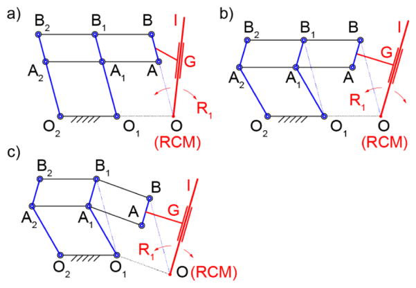
The 1-DoF mechanism of the original RCM [21] is schematically represented in Figure 1a. This is a 6-bar linkage with 8 joints. Here, several of the links and joints are redundant. For example, the kinematics of the mechanism is identical if either link A1A2, A1B1, or both A2B2 and B1B2 are missing. Therefore, the mechanism uses at least 2 parallelogram 4-bar structures to implement a virtual parallelogram OAA1O1, which makes link AB rotate about the remote point O, the RCM point. The remote axis of rotation is normal to the plane of the mechanism at the RCM point. The use of the redundant parallelogram requires precise manufacturing, but improves structural stiffness.
Figure 1.
1-DoF parallelogram RCM types: a) classic – collinearly aligned joints, b) non-collinear vertical links, c) non-collinear
The points A, B, and O are collinear. Since the instrument (I) must cross the point O, it should be angled relative to AB as shown in the figure, either in the mechanism plane or another. Therefore, the end-effector tool/instrument (I) is attached (G, guide) to the link AB and passes the point O, as shown in Figure 1a. An example of a robot with the instrument angled is the LARS robot [28] of the original RCM patent [21]. Another option is to place the instrument I in a parallel plane to clear the interfernece. An example of a robot with this arrangement is the previously mentioned RCM robot built for the MRI [26].
A variation of the parallelogram RCM mechanism is presented in Figure 1b. Here, the vertical links O1A1B1 and O2A2B2 have been “bent” so that their joints are non-collinear. As such, the virtual parallelogram is OBB1O1. This makes the RCM point O non-collinear with AB, allowing more flexibility in mounting the instrument. With this, the instrument may be mounted parallel to AB in the RCM plane (OI || AB).
Finally, the non-colinear joint arrangement can also be applied to links AA1A2 and BB1B2. As shown in Figure 1c, this helps to further displace the RCM point in the other direction. A variation of this with link O2A2B2 straight, O1A1B1 and AA1A2 bent and no redundant A1A2B2B1 parallelogram was constructed for the Steady-Hand Eye Robot [29].
For our application, high structural stiffness was desired to withstand inadvertent forces exerted on the needle-guide by the procedure needle/drill. Since force levels required for clinical use have not been quantified, the design goal was to create a structure as stiff as possible within the MR Safe and size constraints in the MR gantry. Our solution was to use short RCM links, a low OA/OB ratio (relatively short distance to the RCM point), and involve the redundant RCM parallelograms.
The kinematic diagram of the RCM mechanism devised for the robot is shown in Figure 2. This mechanism uses a vertically non-collinear joint arrangement, the redundant parallelogram, relatively short distance to the RCM point, and the needle-guide centered on the joint B. The non-collinear arrangement enabled the bottom joint A to be located aside of the needle-guide. The advantages of this unique arrangement will be presented in the design section and verified experimentally in the results.
Figure 2.
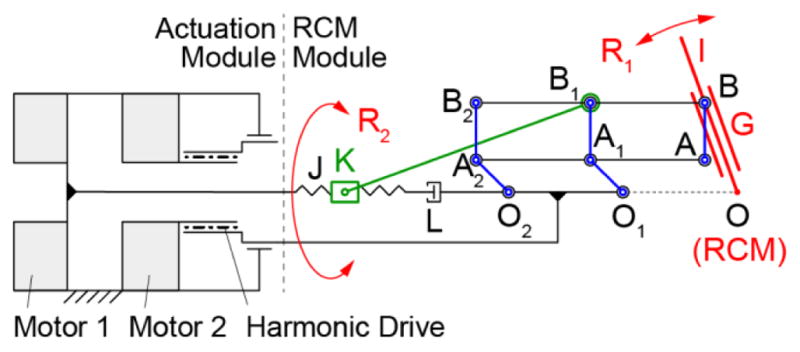
Robot RCM and actuation schematic
The parallelogram mechanism generates the primary RCM rotation R1. This is driven by a spinning-screw (J, revolute joint L) sliding-nut (K) drive, linked with revolute joints to B1. The other RCM rotation R2 is implemented by rotating the base of the parallelogram mechanism about an axis that passes the RCM point (coaxial with OO1O2 for design convenience), as shown in Figure 2. The 2-DoF are driven by motors located in the actuation module which includes a harmonic drive for R2.
III. The Robot Manipulator
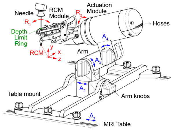
The manipulator design, analysis, and manufacturing codes were built in Creo (PTC, Inc., Needham, MA). The manipulator consists of the 2-DoF RCM module, an actuation module, a passive arm with 3 degrees of adjustment (DoA), and a mount that latches onto the channels of the MRI table, as shown in Figure 3. The arm and mount are made for a long bone biopsy procedure. Other procedures may require different mounts. The position of the robot and respectively its RCM point can be adjusted with 4-DoA, sliding the base on the table channels (A1) and adjusting the positions of the arm (A2–4). These are locked by tightening the respective knobs.
Figure 3.
Manipulator design
For versatility, the manipulator is constructed with a modular structure, so that the actuation module could be reused to drive other robots. This construction is similar to our previously developed robot for prostate biopsy [16]. It consists of two coaxially placed PneuStep motors (Ø70mm × 25mm, 4°/step, 2 encoder counts/step) [30] and a harmonic drive (49:1 transmission ratio) driven by one of the motors (Figure 2).
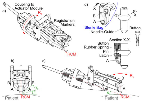
The RCM module detached from the actuation module is shown in Figure 4. The guide is centered on the top joint B by designing the RCM mechanism with a wide structure on both sides of the guide. Joint B is therefore implemented by two coaxial joints BB on the sides, as shown in Figure 4b. Here, if the classic collinear RCM mechanism were used instead, the bottom joints AA would have to be similarly spaced apart, and the angular clearance with respect to the patient would have been γ1 (Figure 4b). However, the non-collinear design, enabled the two joints A to be located closer together, increasing the clearance to γ2(40°)> γ1(20°). In the other direction, clearance with respect to the patient is increased by angling the entire device with angle α(20°), as shown in Figure 4c. The attached animation shows the R1 motion.
Figure 4.
RCM module detached from the actuation base: abc) isometric and orthogonal views, d) link AB, needle-guide, and latching mechanism
The range of the R1 rotation is −50° to +30° implemented with a custom ACME Ø10 × 2mm pitch screw. The step size varies between 0.029 – 0.044°/step, depending on the position of the RCM mechanism. The R2 rotation is unrestricted by the joint, but effectively bounded by the interference with the clinical site (±γ2 =±40° on a flat surface). Its resolution is 0.082°/step.
For sterilization purposes, the entire device can be covered with a sterile bag (Universal Medical EZ-3030). The only component to be sterilized is the needle-guide. The needle-guide can be easily detached by pressing a button (Figure 4d). It also includes a pin that pierces the bag and attaches to link AB, which has a concave structure that follows the outer geometry of the needle-guide to provide a secure and stiff attachment when the latch of the button engages the pin.
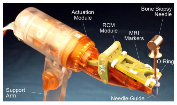
Needles or instruments with diameters up to 10 mm can be guided by the robot by constructing needle-guides with the corresponding bore. The needle used in the current design (Figure 3) is the Invivo 15100 (Schwerin, Germany) MRI bone biopsy set with a cannula diameter of 4.9 mm.
While the needle is manually inserted through the guide, the maximum depth of insertion may be preset by the robot before the insertion. A depth limiter consisting of a rubber O-ring is placed over the barrel of the needle (Figure 5, Figure 6). The needle is inserted through the guide until the ring bottoms on the top surface of the guide. A separate device (1 remote DoF) is used to adjust the location of the ring on the needle barrel prior to its insertion.
Figure 5.
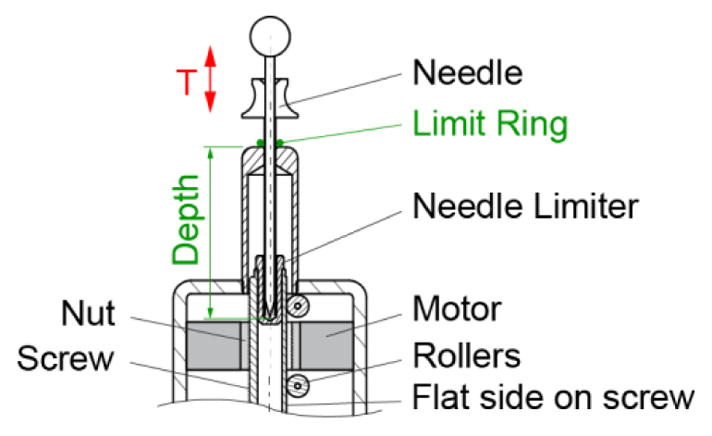
Depth driver to preset the depth of needle insertion
Figure 6.
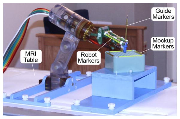
Photo of the robot shown with bone biopsy needle
The depth presetting device is schematically represented in Figure 5. This consists of a third identical PneuStep motor equipped with a central nut (ACME Ø19 × 4.5mm pitch). The nut drives a screw with 3 flat sides spaced at 120°. Six rollers placed in the casing support the screw to implement a prismatic joint. This axis (T) adjusts the location of a limit ring (O-Ring) on the barrel of the needle. The limit ring is initially placed on the barrel close to the point. The needle is then inserted in the device until its point bottoms on the needle limiter, while the limit ring slides on the barrel up to the desired preset depth. The maximum depth of adjustment is 100mm with a resolution pf 0.05mm/step. These should satisfy numerous clinical applications.
A set of 4 registration markers has been built into the BB2 link of the RCM module, as shown in Figure 4a and Figure 6. These are made of glass tubes, filled with Radiance® MRI imaging liquid (Beekley, Bristol, CT).
Two development prototypes of the RCM mechanism were assembeld of mostly 3D printed components. Even for an experienced design team, we found these prototypes to be helpful in the design refinement process along with the CAD models. Computer Numerically Controlled (CNC) manufacturing was then used for the final protoptype (except for 7 3D-printed small cover pieces). The manipulator (Figure 6) and depth presetting device including the motors and encoders are entirelly built of electrically nonconductive, nonmetallic, and nonmagnetic materials. These materilas are plastics (ABS, Acetal Copolymer, Delrin, Nylon 6, Peek 1000, Polycarbonate, Polyetherimide (Ultem 1000), Polyimide, Polyethersulfone (Radel), PTFE (Teflon)), rubber, composites (Garolite, Torlon Polyamide-imide), glass, and high-alumina ceramic. In additiun to mechanical property considerations, material selection included high electrical resistivity and dielectric strength considerations. The links of the RCM are built of Garolite and Ultem, the pins of the joints are made of Garolite rods, with tightly fitted (local interference H7/p6 tolerance classification) Delrin bushings. The needle-guide, which is the only part that comes in direct contact with the patient was built of material with ISO-10993 biocompatible certification (Radel BL033) and withstands steam sterilization at 135°C.
IV. The Robotic System
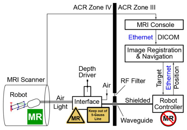
A schematic of the robotic system in the MR environment is presented in Figure 7. The control system is an updated version of our prostate biopsy robot [16]. The Robot Controller is a PC running Windows 10 (Microsoft Corp.) and equipped with a motion control card (MC4000, PMDI, Victoria, BC, Canada). The Controller is MR Unsafe and must remain outside the ACR (American College of Radiology) Zone IV (scanner room), in the ACR Zone III (control room or equipment room) [31].
Figure 7.
System diagram showing placement of MR Safe, Conditional, and Unsafe components
An electro-pneumatic and electro-optical Interface to the 3 PneuStep motors is located in the scanner room (ACR Zone IV), but outside the 0.5 mTesla (5 Gauss) line. The interface is nonmagnetic but uses electricity. For each of the 3 axes, it includes the a PneuStep driver, 3 piezoelectric valves (Hoerbiger PS10021-641A, Germany), and 2 fiber optic sensors (D10BFP, Banner Engineering, Minneapolis, MN). The R1 axis of the robot has no limit switch, and instead a hardware stop is used to home it. The Axis R2 has no limit and uses an arbitrary home. The needle depth Axis T uses an additional fiber optic sensor for homing. The interface also includes an emergency button and status LEDs.
The Depth Driver is conveniently mounted on top of the Interface box. The Interface is connected with 3m long hoses to the robot and with DB25 cables (through the access panel waveguide or its RF Shield) to the Controller. The air supply is typically taken from the medical air port in the MR room, but could be passed through the waveguide as well.
Motion control, safety, and robot kinematics are implemented on the Robot Controller PC under C++ (Visual Studio 2015, Microsoft Corp.) using libraries of the MCC. Safety features include a watchdog, emergency stop buttons, and visual alerts. The watchdog (built on hardware and software) checks the state of several components of the system at 6Hz, immediately disabling power to the pneumatic valves of the electro-pneumatic interface, should a faulty condition occur.
Images are transferred over the network in DICOM format (Digital Imaging and Communications in Medicine) to the Image Registration & Navigation controller implemented on another PC. Image-to-robot registration of the set of markers of the RCM is used to register the robot and MRI spaces. Our previous imaging programs [16, 18] were based on the Amira Visualization software (Visage Imaging, San Diego, CA). for this robot, C++ programs were developed using the open source VTK and ITK toolkits and the GDCM open library for DICOM processing. A custom image-to-model registration algorithm similar to the one that we presented for our transperineal biopsy MrBot [18] robot was used. In short, a CAD model of the markers in the robot coordinate system is superimposed over the MR image of the markers to derive the registration matrix. This then enables the conversion of points between the two coordinate systems, so that points selected in the image are converted to robot coordinates and then joint angles based on the inverse kinematics of the robot.
V. Robot Tests
Extensive bench, imaging, and targeting tests of the robot have been conducted. Errors were calculated as the vector difference between the actual (measured) and set point (target) datasets. Accuracy and precision results were calculated based on the mean and standard deviation of the error vectors. Tests in the MRI were performed in a Siemens Magnetom Aera.
A. Joins Space Set Point Testing
The first tests were performed to verify the positioning ability of the 3 axes of the robot one at a time. The axes were commanded to move over their entire range of motion with 5° increments for R1, R2 and 5 mm for the depth axis T. Measurements were acquired with a protractor (0.25° resolution) and a caliper (0.01 mm resolution). Each experiment was repeated 3 times.
B. RCM Check and Robot Space Set Point Testing
An optical tracker (Polaris, NDI, Canada) was used to measure the position of an optical marker on a slender rod placed through the needle-guide of the robot (at ~208 mm from the RCM point), as shown in Figure 8. The manufacturer stated RMS error of the Polaris is 0.35 mm. Measurements were performed close to the tracker, with the marker at rest, and 500 repeated measurements were averaged at each static location. For these measurement conditions, the accuracy of this optical tracker may be as low as 0.055 mm [32].
Figure 8.
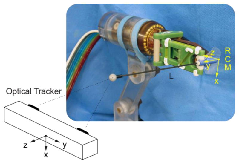
Robot tests with an optical tracker
The R1 axis was commanded to move to N1 =15 positions (−45° to 25° with 5° increments), and for each the R2 axis was moved to N2 =16 positions (0° to 180° with 12° increments). The actual position of the marker in tracker coordinates, Taij| i =1,2,…, N1 j = 1,2, …, N2, was measured at all these 240 positions. Since R1 and R2 are the axes of the RCM mechanism, the set of points Ta should lie on a sphere. As such, the set was fitted to a sphere using a Gauss-Newton least squares algorithm (in Matlab, MathWorks, Inc.). The center of the sphere is TO. The length of the rod from the RCM point to the center of the marker (L) was estimated as the radius of the sphere. Having L and the joint axes positions, allowed the calculation of the set point dataset in robot coordinates Rsij | i =1,2, …, N1, j =1,2, …, N2 through the direct kinematics. Then, a rigid point-cloud registration (F) between the robot and tracker spaces, was derived using Horn’s method [33]. The registration allowed transformations of the datasets between the robot and tracker spaces: and . Robot positioning errors were then calculated as the difference between the actual and set point datasets in the same frame Re = Ra − Rs. The error of the RCM location is the fitted sphere center in the robot coordinates . The angular error of the robot was calculated in degrees as ɛ =180 Re/(Lπ). For clinical purposes, the estimated targeting error that may be expected due to the robot is eR= Re/L for each mm of target depth.
C. Set Point Repeatability Testing
Using the same optical tracker setup, the robot was sent to 9 set positions at R1 = {−15°,0°,15°} and R2 ={−15°,0°,15°}. Each position was approached on each axis from ±5° of the position, as shown in Figure 9. The experiment was repeated 5 times for a total of 9×4×5=180 tests. Tracker measurements were acquired at the 9 set point positions. The angular errors were calculated as in the previous test. The repeatability was calculated as the standard deviation of the angular errors.
Figure 9.
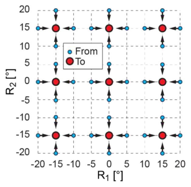
Repeatability test points in joint space
D. Stiffness Testing
The robot was mounted in the vise of a vertical milling machine as shown in Figure 10. A compression spring (McMaster Carr 9657K145, zinc-plated steel, 3.125″ L, 0.75″ OD, 0.091″ wire diameter, calibrated elastic constant 4.123 N/mm) was mounted in the spindle of the machine (stopped, no spin). A feed of the machine (0.01 mm resolution) compressed the spring against the needle-guide in a direction passing the RCM point, to generate the desired load. A micrometer (0.01 mm resolution) was placed on the opposite side to measure the deflection under the load. Experiments were performed in axial (-Y) and lateral (X) directions to the guide. Forces between 0 and 35N were applied in 20 values and the corresponding deflections were recorded. The force-deflection data was then fitted linearly.
Figure 10.
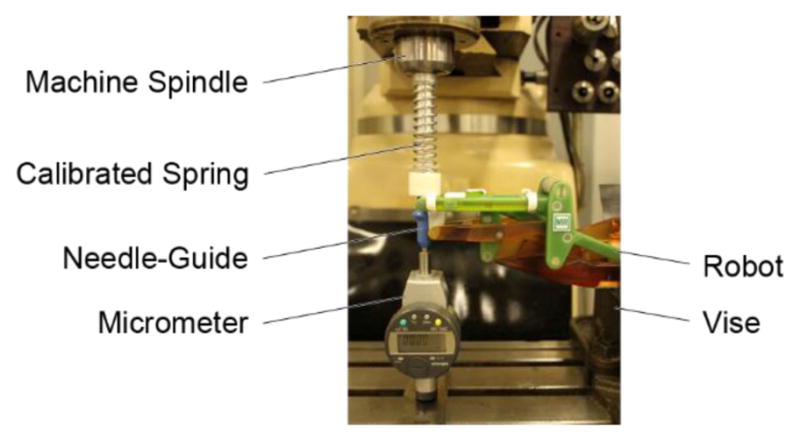
Stiffness test setup in a milling machine
E. MR Safe Testing
The robot was tested according to ASTM F2503-13 and its derived test standards (Table X1.1 of [8]). The scientific rational was first employed based on the component materials of the manipulator. The robot was then tested for the Static magnetic field-induced displacement force (ASTM F2052) and torque (ASTM F2213) by suspending the manipulator at the entrance of the MR system bore by its hoses and by a string and measuring the hose/string deflection angle and observing the torque. The sting supported device was moved with the table through the entire bore while inspecting the possible motion of the device due to induced effects. The RF field-induced heating (ASTM F2182, ISO TS 10974) and Gradient field-induced heating and vibration (ISO TS 10974) were performed by direct observation. The Gradient and RF field-induced voltage tests (ISO TS 10974) do not apply to dielectric materials. Similarly, malfunction of the device due to the static, gradient, or RF fields (ISO TS 10974) does not apply. However, it was explored during the EMC testing and DIGI targeting tests presented next. Evaluation of the MR images according to ASTM F2119 is designed for implants, and was not possible (it was not advisable to immerse the robot in a solution). Instead, alternative tests were used as shown in the following sections. The Interface controller is designed to remain outside the 0.5 mTesla (5 Gauss) line. This was carefully brought in the MR room while observing possible induced forces. The system components were labeled according to ASTM F2503-13 (Figure 6, Figure 7).
F. Electromagnetic Compatibility (EMC) Testing
Although the manipulator is immune to electromagnetic disturbances from the MR scanner due to its MR Safe materials, there is the potential for electromagnetic (EM) interference from the control components of the robot which are electric. The Interface is connected with a shielded DB25 cable to the Robot Controller (Figure 6) either directly through the waveguide or passing through the RF filter of the access panel. The waveguide connection is preferable because it is independent of the RF filter implementation, and is portable across imaging modalities. For EMC testing this connection provides the reasonably foreseeable maximum of the EM disturbances.
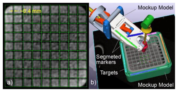
The same mockup was used in all tests involving the MR. This is a geometric mockup designed in the shape of a rectangular basin with square grids at the top and the bottom, and with linear MR markers that can be used for registration (Figure 11b). The mockup was 3D printed of plastic and filled with a solution of 0.5% Magnevist (Bayer HealthCare LLC) in water by volume. The markers were filled with the Radiance contrast, as used in the robot markers. The mockup was mounted with a support on the MR table and positioned at the bore isocenter.
Figure 11.
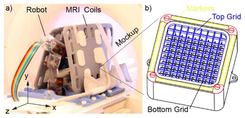
a) Robot and mockup within MRI coils, b) The mockup (grid slots 10mm, grid wall 1mm, top grid height 5mm, distance between top and bottom grids 30mm)
EMC testing followed the IEC 60601-1-2 [34] standard, which the FDA recognizes as a consensus standard [35]. Reasonably foreseeable RF emissions may be transmitted by the Interface controller to the MR environment and induced by the MR environment into the Interface and subsequently retransmitted into the RF antenna of the MRI. The white pixel or noise test is a test commonly performed at the installation of the MR scanner and its room shield, and then performed during service and maintenance of the MR to measure EM noise levels in the MR environment. Here, we used the test to measure the EM emissions augmented by the robotic system. The test is commonly available on MR scanners and consists of a series of MR sequences run with the RF transmitter of the MR turned off. Instead, the RF signals that the MR antennas capture are originating from external sources, from improper shielding of the MR room, or, in our case from the robotic system. To separate the causes, three test setups were used, as shown in Table 1.
Table 1.
Test configurations with and without the robot.
| Test with | Description |
|---|---|
| No Robot (N) | Mockup at MR isocenter with MR coils in place, manipulator and Interface controller outside of the MR shield and unpowered. |
| Robot Active (A) | Mockup and coils unchanged from N, manipulator in operative position about the MR isocenter, and the Interface controller outside the 5-Gauss line. All system components connected, powered, robot in ready to move state but at rest. |
| Robot in Motion (M) | Same as A-test, but with the robot in continuous motion. |
Note: We found that it is preferable to perform the tests in the reversed order, because it is easier to remove rather than placing components without changing the mockup and coils position.
Six noise tests were performed in each of the 3 test configurations. The base line test (N) establishes the normal level of noise in the MR environment. The other two are used to determine the additional noise caused by the presence of the robotic system (A) and its motion (M) relative to the no robot case (N).
G. Image Quality Testing
The tests are based on the methods presented in [5, 36], updated in [16], and are further refined herein. The N, A, and M test conditions described in Table 1 were used. Images were acquired over the entire mockup using a T1 (Short T1 Inversion Recovery) and a T2 sequence with coronal slices (ZX plane in Figure 11a). Their sequence parameters were maintained throughout all the tests. Coronal images were chosen as being normal to the typical direction of needle insertion for this robot/procedure. All images were acquired with two Body 18 coils, Siemens Healthcare (Figure 11a). For each sequence type, we acquired three N image sets, two A sets, and two M sets. For all tests it is essential that the MR coils are not moved. These should be placed so that they do not interfere with the robot and its motion, and that the robot may be placed or removed without moving the coils.
The tests were designed to establish quantitative image deterioration metrics due to the robot active (A) relative to the N case, and due to its motion (M) relative to the A case. Images were analyzed for: 1) Signal to noise ratio (SNR) changes, 2) Image change factors, and 3) Geometric artifacts.
G1. SNR Testing
The SNR is calculated based on the NEMA standard MS 1-2008 [37], Method 1. A region of interest (ROI) is defined within signal-containing images centered over the mockup. The same ROI is used in all tests. The SNR calculation requires two equivalent image sets {I, J}. For each slice s: 1 → nROI of the ROI, the signal S is calculated as the average pixel intensity values pIs in one of the sets. The noise N is calculated based on the standard deviation of the pixel-by-pixel difference image between the two sets:
| (Eq. 1) |
The SNR is calculated for each of the ROI slices, for the following pairs of sets: {N1, N3}, {N2, N3}, {A1, A2}, {M1, M2}. The relative changes in SNR are:
| (Eq. 2) |
Equation 2 gives the three ΔSNRs values for each slice of the ROI. These are plotted versus the image space coordinate of the slices, separately for the T1 and T2 sequences. The results are also averaged over the slices, for each sequence type, to determine the global metrics:
| (Eq. 3) |
As such ΔSNR{N–N} quantifies the normal change in SNR between consecutively acquired image sets, in the absence of the robot to be tested, and sets the non-interference goal. The ΔSNR{A–N} quantifies the SNR changes caused by the robot presence. Last, ΔSNR{M–A}quantifies the component of SNR changes caused by the robot motion.
G2. Image Change Factors
The SNR tests do not account for possible image artifacts induced by the presence and motion of the robot. Image change tests quantify the differences between the A–N and M-A sets. The N1, N2, N3, A1, and M1 sets from both the T1 and T2 sequences are used. There is no need to reacquire these, since they are available from the SNR tests. The ROI is the same one used in the SNR.
Image change (deterioration) metrics [36] are reciprocal to image similarity metrics commonly used in image-based registration [38]. Here, we use the image deterioration factors described in [5]. These are updated to reflect the combined test with the SNR and to increase the sensitivity.
For a pair of image sets {I,J}, where I and J are the tested respectively the reference images, an Image Change Factor (ICF) can be calculated for each pair of slices s: 1 → nROI within the ROI as:
| (Eq. 4) |
where the numerator is the average of the absolute values of the pixel-by-pixel difference between the pixel intensities form the 2 sets. The denominator is the average of the pixel intensities over the entire ROI. With this, quantifies the normal variability between consecutively acquired image sets, in the absence of the robot, and gives an estimate of the non-change goal. The ICF differences relative to it are:
| (Eq. 5) |
Equation 5 gives ΔICFs values for each slice of the ROI. These are plotted versus the image space coordinate of the slices, for T1 and T2. The results are averaged over the slices, for each sequence type, to determine the global metrics:
| (Eq. 6) |
Similar to the SNR tests, ΔICF{A–N} quantifies the changes caused by the robot presence, and ΔICF{M–A}quantifies the component of the image changes caused by the robot motion alone. As in the SNR tests, negative values represent a loss.
G3. Geometric Artifacts
The geometric accuracy of the images is critical for the accuracy of image-guided targeting using the robot. The ICF test above is sensitive to A–N geometric artifacts. However, it is unlikely but possible that a geometric artifact would not be detected by the ICF (i.e. a shift equal to the pattern increment of a checker pattern image). Moreover, the ICF does not depict artifacts of the N set, of the MRI itself. For this, an additional visual inspection of the imaged shape of the grid of the mockup is helpful.
The mockup (Figure 11b) was instrumented with a set of image-markers that are similar to those of the robot. One of the N image sets (that contains the mockup markers) is used. The mockup markers are used to register the CAD model of the mockup to the image. The mockup-to-image registration is performed similar to the robot-to-image registration described in Section IV. Based on the registered model, a grid of lines that corresponds to the grid of the mockup is overlaid over the images. Visual inspection is then used to observe if the lines overlap the imaged grid. If observable, the misalignment could be quantified as a measure of the geometric artifacts.
H. Image-Guided Targeting
The same mockup was used. A new set of images (T1) was acquired to include the robot markers as well as the mockup (Figure 12). The robot and the mockup were registered to the image space. An additional marker (similar construction) was initially placed through the needle guide to image the guide direction.
Figure 12.
The robot and mockup attached to the MRI table for the image-guided targeting tests
The clinical MRI bone biopsy needle Invivo 15100 is metallic. For the experiments, a needle with the same diameter was made of clear Acrylic plastic. Even though clinically the targeting errors will be more difficult to measure due to the metal artifacts from the needle, for this test the location can be more exactly measured without the artifacts. The plastic needle does not influence the accuracy results of the robot, because the artifact from the needle comes after aligning the guide on target, and inserting it. Then, no final adjustments were made. In the real case a marker may be placed through the guide for trajectory verification before inserting the actual needle, as shown in Figure 12.
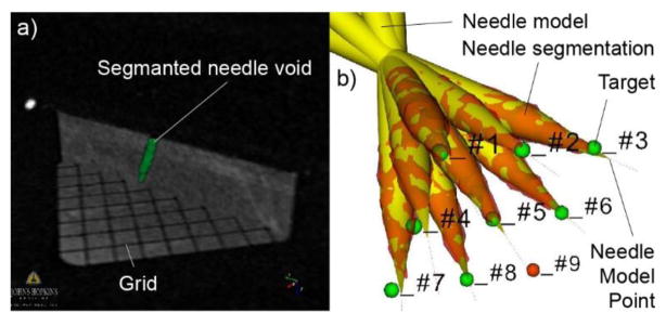
Nine taret points were defined at the centers of the bottom grid of the mockup. These were successively selected as targets in the image navigation software. The robot adjusted the orientation of the needle-guide and preset the depth of insertion. The plastic needle was manually inserted through the guide up to the indicated depth. No manual adjustments were made. The entire experiment was then repeated, for a total of 18 targets. Images were acquired for confirmation after each insertion with the needle in place. The images show the void of signal in the region displaced by the needle. This region was segmented based on a Marching Cube algorithm [39]. The direction of the needle was determined with a principal components analysis. The depth of the needle was adjusted along the direction so that the model of the needle overlapped its image. The distance between the point of the needle model and target point was measured as the 3D targeting error. The distance from the target to the needle direction was also measured as the 2D error. The average of the target depths (from the RCM point) is calculated and named dt. The accuracy (A(dt)) and precision are calculated as usual, as the average respectively the standard deviation of the errors.
Based on these and the bench test results (Section B2), the accuracy components that are due to factors other than the robot may be estimated as:
| (Eq. 7) |
Therefore, robot’s best expected accuracy at a depth of d under MRI guidance can be estimated as:
| (Eq. 8) |
Here, the coefficient eR depends on the robot itself, but A(0) depends on the imaging modality.
VI. Results
A. Join Space Positioning Testing
The accuracy and (precision) for the R1, R2, and T axes were 0.11° (0.14°), 0.0° (0.0°), respectively 0.01 mm (0.02 mm).
B1. RCM Mechanism Check
The radius of the sphere fitted to the measured dataset was L=208.574 [mm]. The center of the fitted sphere in robot coordinates was RO = (0.174, 0.061, 0.204) [mm] (Figure 13). The average distance from the measured dataset Tα to the surface of the fitted sphere was 0.136 mm (SD 0.175 mm).
Figure 13.
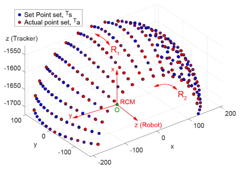
RCM mechanism and set point accuracy tests
B2. Robot Space Set Point Testing
The average errors between the actual and set point datasets was 0.645 mm (SD 0.279 mm). The angular accuracy and (precision) of the robot were 0.177° (0.077°). The estimated component of targeting errors due to the robot is eR(10) = 0.031 mm (SD 0.013 mm) per cm of target depth.
C. Set Point Repeatability Testing
The repeatability measured 0.136°. The manipulator has no perceivable play or backlash in any direction and appears stiff.
D. Stiffness Testing
The force/deflection diagrams of the robot at the needle-guide in the axial and lateral directions are presented in Figure 14. Based on the linear fit, the stiffness of the robot at the needle-guide is 33.38 N/mm axially and 25.53 N/mm laterally. Therefore, a displacement between 0.29–0.38 mm can be expected if the guide is inadvertently pushed with 1 Kgf. During the forcing experiments the needle-guide did not detach from the robot.
Figure 14.
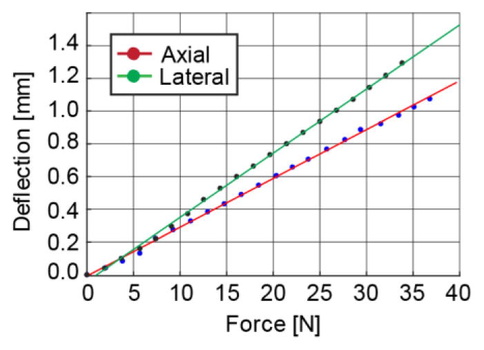
Robot stiffness in axial and lateral directions to the needle-guide.
E. MR Safe Testing
The manipulator is MR Safe according to ASTM F2503-13 because “An item composed entirely of electrically nonconductive, nonmetallic and nonmagnetic materials may be determined to be MR Safe by providing a scientifically based rationale rather than test data” [8]. Several tests were still performed for additional verification. Photos taken during the force and torque measurement experiments are shown in Figure 15. The induced force and torques were below a perceivable level. There was no observable induced heat or vibrations. There was no observable induced force on the Interface controller outside the 0.5 mTesla (5 Gauss) line.
Figure 15.
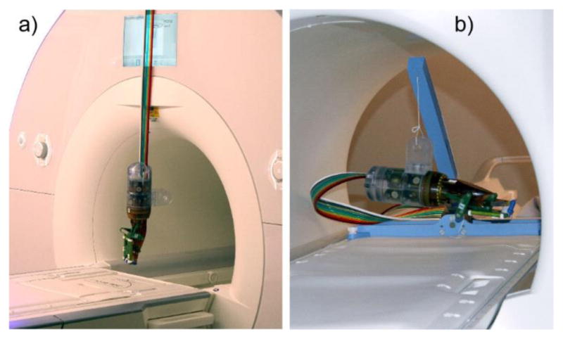
Induced force (ASTM F2052) and torque (F2213) tests with robot suspended by a) its hoses and b) a string.
F. EMC Testing
Six each of the N, A, M test results are overlaid in the Figure 16 graph. For all 18 tests the results were virtually identical, with somewhat different peaks around 13.5MHz. On the Siemens MR used, the noise was reported in arbitrary units [au]. However, the results show that the robotic system and its motion did not observably change the EM emissions on a wide spectrum of frequencies. This is a very sensitive test. For example, additional noise is observable if the test is run with the MR door open.
Figure 16.
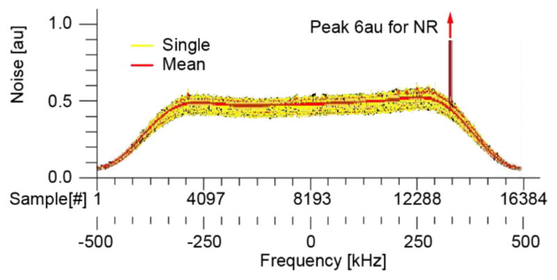
EMC test results. Spectrum of the noise in frequency domain (au = arbitrary units).
G1. SNR Testing
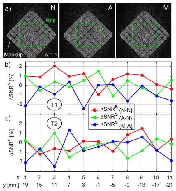
The results of the SNR tests are presented in Figure 17. A rectangular ROI, 140 × 140 [pixels], centered over the mockup, comprising coronal slices starting on bottom grid and ending on the top grid (11 slices, thickness = 4mm) was used. Corresponding images taken at the same location throughout the mockup from the N, A, and M sets are shown in Figure 17a, together with the ROI. The images show no observable relative differences.
Figure 17.
SNR change due to the presence and motion of the robot: a) Slice 1 images N, A, M from the T2 set and the ROI, b) SNR change for T1, and c) T2 sequences.
The results of the SNR changes for the T1 and T2 sequences are shown in Figure 17bc. The normal fluctuations in SNR of the scanner itself are approx. −1% to +2%, for both sequences. With the robot the SNR change was similar (−1.6% to +1.5%). Setting the robot in motion makes the range 0.5% wider (−2.5% to 1.35%). The changes were similar for the 2 sequence types. The global ΔSNR metrics are presented in Table 2.
Table 2.
Global SNR and ICF results (− is loss, + is gain)
| Sequence type: | T1 [%] | T2 [%] | ||
|---|---|---|---|---|
| ΔSNR | ΔICF | ΔSNR | ΔICF | |
| Normal: {N – N} | 0.728 | −0.045 | −0.105 | −0.128 |
| Due to robot: { A – N } | 0.144 | −1.601 | −0.352 | −1.425 |
| Due to motion: {M – A } | −0.855 | −0.039 | −0.638 | −0.419 |
G2. ICF Testing
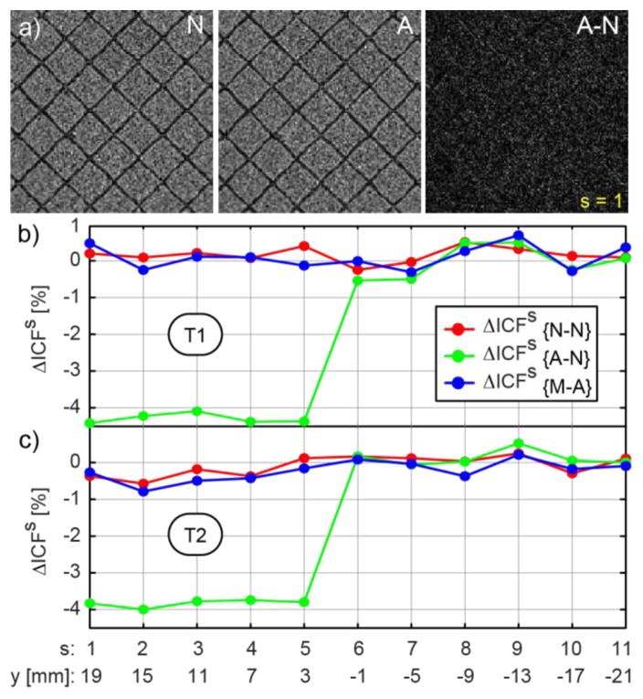
The results of the ICF tests are presented in Figure 18bc. An {R–N} change is observable in several slices. These correspond to the grid of the mockup. The difference image at one of these slices is shown in Figure 18a. Here, a very slight contour of the grid is visible, suggesting a relative shift of the N and A images. The cause is unknown. It could be due to slightly displacing the mockup at the time when the robot was removed before the N experiments (order: A, M, N). Comparatively, a simulated shift of the mockup in the T2 set with one pixel (pixel size 0.468mm) makes ΔIDFs ≅ 8%. The global ΔIDF metrics are presented in Table 2. Based on the original IDF definitions of [5], the passive and active image deterioration factors over the entire mockup are EP = −1.04 · 10−6 [%] and EA=−4.84 · 10−8 [%], which are typically unobservable to radiologists.
Figure 18.
ICF due to the presence and motion of the robot: a) Slice 1 ROI images N, A, and A–N from the T2 set, b) ICF for the T and c) T2 sequences
G3. Geometric Artifacts
An image of the bottom grid with the model grid overlapped is shown in Figure 19a. The images show a slight misalignments of the grid towards the perimeter on the order of 0.4mm.
Figure 19.
a) Model grid superimposed over image of grid, and b) Augmented reality displayed by the navigation software: Robot and mockup models registered to the image space. Nine targets defined at the centers of the bottom grid.
H. Image-Guided Targeting
The augmented reality display of the navigation software is shown in Figure 19b. This displays the robot and mockup registered to the segmented markers, together with the 9 targets. One of the 9 targets was excluded at the time of the experiment because at that orientation the needle touched the top grid. Images of 8 of the inserted needles are shown n Figure 20b. Average target depth was dt = 37.91 (SD 1.12). The accuracy and precision results of the 16 experiments are listed in Table 3, together with the estimated accuracy at a target depth A(d), and an example at 7cm, A(70).
Figure 20.
Imaged needle at targets: a) Segmented needle at one location together with 2 image slices showing the grid and a needle slice, and b) Needle model registered to the needle segmentation. Actual needle point from the model and target.
Table 3.
Image-guided targeting results
| 2D [mm] | 3D [mm] | |
|---|---|---|
| Max Error | 1.82 | 2.65 |
| Accuracy A(dt) | 1.19 | 1.71 |
| Precision | 0.45 | 0.51 |
| Accuracy A(d) | 1.07+0.0031 · d | 1.59+0.0031 · d |
| Accuracy A(70) | 1.29 | 1.81 |
VII. Discussion
We reported the development and preclinical testing of a new robot for image-guided interventions. This uses an innovative parallelogram type RCM structure with non-collinear links. This design results in increased lateral clearance with respect to the patient and high structural stiffness. The stiffness at the needle guide measured 33 N/mm, the RCM mechanism has no perceivable backlash, and the RCM mechanism describes a sphere within a tolerance of 0.136 mm. These results were achieved with relatively high-power motors, a stiff structure that included numerous Garolite (fiberglass) components, and tightly fitted joints. A relative comparison with similar robots is difficult because stiffness is not normally reported, but subjectively it appears very stiff. Numerically, a 1Kgf of inadvertent force exerted in either direction on the guide at the RCM point yields to a deflection smaller than 0.38mm.
The needle-guide is the only component that must be sterilized. Its latching mechanism and convex-concave mating profiles work through the sterile bag, mount precisely, and are extremely stiff (the force was exerted on the guide in the stiffness experiments, through the latch). The latch did not detach or break up to the 35N level exerted axially or laterally. Many other applications could use a similar design.
Most IGI robots orient a needle guide, but the depth of insertion is manually set. Setting the depth manually works well if real-time images are readily available from the specific imager, for example under ultrasound guidance. Under MRI guidance, however, the access to the needle in the scanner combined with the special sequences required for near-real-time imaging make it helpful to have the depth of insertion preset by the robot. Here, we use a remote DoF to preset the depth. This feature was derived from our driver for the transrectal biopsy robot [16] and is updated with the O-Ring type spacer and a new mechanism. This feature fits into the anticipated clinical workflow, and did not appear to contribute to errors (our 3D minus 2D accuracy is 0.52mm, which includes this as well as the registration errors of the needle model to its image). Of course the O-Ring mark can be moved if the operator pushes it excessively into guide, but we found that it was easy to operate properly during our mockup study. The O-Ring stopper could be used in many other applications.
The control system is similar to our previous design [16]. Piezoelectric valves are used and these are located in the MR room outside the 5 Gauss line. We found this to be a substantial advance over the voice-coil type valves that we used before [40]. Having the valves in the room makes the hoses shorter and eliminates the need for a connector on the hoses as well as the optical fibers. We feel that the system diagram in Figure 7 is highly appropriate for MR Safe robots, and this configuration could be used for other applications.
A comprehensive set of tests were performed. These were synthesized based on international standards, our experience of nearly 2 decades of building MRI robots, and with the FDA approval process of another MR robot [18]. These start with kinematic tests of the robot itself, which are essential to set the accuracy base and quantify error components. ASTM tests for the magnetic resonance environment are included. If a device requires FDA approval (SR), the ASTM MR Safety and EMC tests are required by the FDA. For the EMC testing, we describe here how the MRI itself can be used as an EM emission meter. Low EM test results are also supportive for multi-imager compatibility, since the MR tests it on a wide frequency spectrum.
The markers that we use in the mockup are similar to those of the robot, and so were the registration algorithms used for the robot-to-image and mockup-to-image registrations. As such, we believe that if the robot is MR Safe (test E), if the robot is accurate (test B2), and if the grid properly overlaps the mockup (test G3), then the robot should be accurate in DIGI targeting. Since MRI testing is expensive, one could initially use only tests E, B2, and G3 and refine the robot and software, before proceeding to the other tests. In corollary, if tests B2 or G3 are not acceptable, IGI targeting (test H) should probably not be undertaken.
If used with other imaging modalities, the glass tubes of the robot registration markers could be filled with an appropriate contrast, or with mixtures of the contrast solutions if used in cross-modality IGI. In this case, test G3 should use the same type of contrast.
The change in SNR tests described in [16] were updated here with a base level measurement {N–N}. We feel this is very useful to set the base level of the tested device. Then, the image deterioration factors of [5, 36] were updated here to integrate with the SNR tests and to increase their sensitivity. The measures are similar, but the magnitude is higher (i.e. −0.352% vs. −1.04 · 10−6).
The tests were devised to isolate the errors components as much as possible. This enabled the estimation of targeting accuracy at a given depth, A(d). Of course, additional errors such as soft tissue and needle deflection will be present in-vivo. But the in-vitro estimate should help to estimate if the device is inappropriate to a specific clinical case. If the target is smaller than A(d), the robot will probably not work under the tested imaging modality (In Equation 8, A(0) depends on the imaging modality). Additional tests with the specific imager are needed if another is used. This accuracy estimation is a new approach, which we believe could be useful for other researchers.
In summary, our research was built upon numerous previous technical achievements. The principal new developments include the RCM mechanism, stiff structure, and the detachable needle-guide. The paper also reports a very comprehensive set of preclinical tests. To the best of our knowledge this is the most comprehensive testing methodology reported to date for MR robots. It incorporates previous methods, regulatory tests, but also the new Image Change Factors and the new analysis of component errors in Image-Guided Targeting. This is also one of the few papers to report the stiffness of the manipulator, a critical element for IGI targeting. The paper also reports several of our know-how lessons that we have learned, for example how to setup the tests in order to reduce the expense with the MRI.
VIII. Conclusion
Preclinical tests show that the robot is MR Safe, no EM emissions were found, has no observable mutual interference with the MRI, has a stiff structure, suggest that the robot is multi-imager compatible, and may be applicable to direct MR-guided interventions that require more than 1.07+0.0031 · d [mm] accuracy in 2D or 1.59+0.0031 · d [mm] in 3D. At a target depth of 7cm for example, these are 1.29 mm respectively 1.81 mm. Since other imagers (i.e. the CT) are typically more accurate geometrically than the , the accuracy limits above appear safe to use for other imaging modalities. If more accuracy is needed, the error components related to the images (A(0)) could be further improved for the MR or other modalities.
In summary, we report a new MR Safe robot, that is relatively simple and accurate.
Acknowledgments
The project described was supported by awards 1R01CA172244 from the National Cancer Institute, and in part by RC1EB010936 from the National Institute of Biomedical Imaging and Bioengineering, and award W81XWH0810221 from the Department of Defense.
Biographies

Dan Stoianovici (ASME M’1994) received the Ph.D. degree from Southern Methodist University, Dallas, TX, in 1996. He is Professor of Urology, Mechanical Engineering, Neurosurgery, and Oncology at the Johns Hopkins University. He is also the Director of the Urology Robotics Program. His specialty is medical robotics in particular robotic hardware and image-guided robots. His bibliography includes numerous publications and 22 patents of invention. He serves on the editorial boards of the IEEE/ASME TRANSACTIONS on Mechatronics, Journal of Endourology, International Journal of Medical Robotics and Computer Aided Surgery and other cross disciplinary medical-engineering journals.

Changhan Jun received a B.S. degree from the Department of Mechanical, Materials and Aerospace Engineering, Illinois Institute of Technology, Chicago, IL, USA in 2010. He received a M.S. degree at the Department of Mechanical Engineering, Johns Hopkins University, Baltimore, MD, USA in 2013. Since 2012, he studies toward a Ph.D. degree at Urology Robotics Laboratory, Johns Hopkins University, Baltimore, MD, USA. His research interests include image-guided robots and medical devices.

Sunghwan Lim received the B.S. degree from the Department of Mechanical Engineering and Materials Science, Yokohama National University, and the M.S degree from the Department of Bioengineering, The University of Tokyo, Japan, in 2008 and 2010, respectively. From 2010 to 2012, he was an Instructor at the Gondar Polytechnic College, Ethiopia. From 2012 to 2014 he was Research Scientist at the Biomedical Research Institute, Korea Institute of Science and Technology, Seoul, Korea. He is currently working toward the Ph.D. degree at The Johns Hopkins University, Baltimore, MD, USA. His research interests include image-guided medical robots and medical imaging.

Pan Li received a B.S. degree from the Department of Mechanical Engineering, Wuhan Polytechnic University, China in 2012. She received a M.S. degree at the Department of Mechanical Engineering, Tianjin University, Tianjin, China in 2014. Since 2014, she studies toward a Ph.D. degree at the Department of Mechanical Engineering, Tianjin University. Currently, she in an exchange student at the Urology Robotics Laboratory, Johns Hopkins University, Baltimore, MD, USA. Her research interests are medical image processing and needle steering.
Doru Petrisor (ASME M’2003) received a MS degree in Mechanical Engineering from the University of Craiova, Romania in 1988, the PhD from the University of Petrosani, Romania in 2002, followed by a research fellowship in Urology at the Johns Hopkins University. Between 1991–1994 he was Assistant Professor at the University of Craiova and Lecturer since 1994. In 2002 he joined the Urology Robotics research group at Johns Hopkins and currently is Research Associate Professor. Dr. Petrisor’s specialty is design and manufacturing of medical devices. His bibliography includes numerous articles, presentations, and 4 patents of invention.

Stanley Fricke received his Nuclear Engineers degree from the Massachusettess Institute of Technology, Cambridge, MA. in 1991. He is Professor of Radiology, of Pediatrics and of Integrative Systems Biology at George Washington University and Adjunct Professor of Oncology at Georgetown University Medical Center. His speciality is Magnetic Resonance Imaging, safety and testing. His bibliography includes numerous publications and 3 patents of invention. He serves on several NIH and VA grant review study sections.

Karun Sharma received a BS degree in Biology from William and Mary in 1994, a MS degree in Anatomy from the Medical College of Virginia in 1994, followed by a MD/PhD from the Medical College of Virginia in 2001. He is an Assistant Professor of Radiology and Pediatrics at George Washington University. At Children’s National Medical Center, he is the Director of Interventional Radiology. His main research areas include MRI compatible robotics and high intensity focused ultrasound.

Kevin Cleary received a BS and MS degree in Mechanical Engineering from Duke University in 1982 and 1983, followed by a PhD from the University of Texas in 1990. He is a Professor of Radiology and Pediatrics at George Washington University. At Children’s National Medical Center, he is the director of the Bioengineering Initative, where he works with his clinical partners to bring technology to assist in pediatric care. His main interests include medical robotics, rehabilitation robotics, and biomedical devices.
References
- 1.Taylor RH, Stoianovici D. Medical robotics in computer-integrated surgery. IEEE Transactions on Robotics and Automation. 2003 Oct;19(5):765–781. [Google Scholar]
- 2.Mozer P, Partin AW, Stoianovici D. Robotic Image-Guided Needle Interventions of the Prostate. Reviews in Urology. 2009 Winter;11(1):7–15. [PMC free article] [PubMed] [Google Scholar]
- 3.Cleary K, Melzer A, Watson V, Kronreif G, Stoianovici D. Interventional Robotic Systems: Applications and Technology State-of-the-Art. Minimally Invasive Therapy & Allied Technologies. 2006;15(2):101–113. doi: 10.1080/13645700600674179. [DOI] [PMC free article] [PubMed] [Google Scholar]
- 4.Stoianovici D. Technology Advances for Prostate Biopsy and Needle Therapies. Editorial. Journal of Urology. 2012 Oct;188(4):1074–1075. doi: 10.1016/j.juro.2012.06.127. [DOI] [PubMed] [Google Scholar]
- 5.Stoianovici D. Multi-Imager Compatible Actuation Principles in Surgical Robotics. International Journal of Medical Robotics and Computer Assisted Surgery. 2005 Jan;1(2):86–100. doi: 10.1002/rcs.19. [DOI] [PMC free article] [PubMed] [Google Scholar]
- 6.Elhawary H, Tse ZT, Hamed A, Rea M, Davies BL, Lamperth MU. The case for MR-compatible robotics: a review of the state of the art. Int J Med Robot. 2008 Jun;4(2):105–113. doi: 10.1002/rcs.192. [DOI] [PubMed] [Google Scholar]
- 7.Fischer GS, Krieger A, Iordachita I, Csoma C, Whitcomb LL, Gabor F. MRI compatibility of robot actuation techniques--a comparative study. Med Image Comput Comput Assist Interv. 2008;11(Pt 2):509–517. doi: 10.1007/978-3-540-85990-1_61. [DOI] [PMC free article] [PubMed] [Google Scholar]
- 8.ASTM F2503–13: Standard Practice for Marking Medical Devices and Other Items for Safety in the Magnetic Resonance Environment. doi: 10.6009/jjrt.2018_JSRT_74.7.739. Available at: http://compass.astm.org/EDIT/html_annot.cgi?F2503+13. [DOI] [PubMed]
- 9.CFR - Code of Federal Regulations Title 21, Part 812 Investigational Device Exemptions. Available at: http://www.accessdata.fda.gov/SCRIPTs/cdrh/cfdocs/cfCFR/CFRSearch.cfm?CFRPart=812.
- 10.Tokuda J, Song SE, Fischer GS, Iordachita, Seifabadi R, Cho NB, Tuncali K, Fichtinger G, Tempany CM, Hata N. Preclinical evaluation of an MRI-compatible pneumatic robot for angulated needle placement in transperineal prostate interventions. Int J Comput Assist Radiol Surg. 2012 Nov;7(6):949–957. doi: 10.1007/s11548-012-0750-1. [DOI] [PMC free article] [PubMed] [Google Scholar]
- 11.Tse ZTH, Elhawary H, Zivanovic A, Rea M, Paley M, Bydder G, Davies BL, Young I, Lamperth MU. A 3-DOF MR-compatible device for magic angle related in vivo experiments. Ieee-Asme Transactions on Mechatronics. 2008 Jun;13(3):316–324. [Google Scholar]
- 12.Zangos S, Melzer A, Eichler K, Sadighi C, Thalhammer A, Bodelle B, Wolf R, Gruber-Rouh T, Proschek D, Hammerstingl R, Muller C, Mack MG, Vogl TJ. MR-compatible assistance system for biopsy in a high-field-strength system: initial results in patients with suspicious prostate lesions. Radiology. 2011 Jun;259(3):903–910. doi: 10.1148/radiol.11101559. [DOI] [PubMed] [Google Scholar]
- 13.Yakar D, Schouten MG, Bosboom DG, Barentsz JO, Scheenen TW, Futterer JJ. Feasibility of a pneumatically actuated MR-compatible robot for transrectal prostate biopsy guidance. Radiology. 2011 Jul;260(1):241–247. doi: 10.1148/radiol.11101106. [DOI] [PubMed] [Google Scholar]
- 14.Schouten MG, Ansems J, Renema WK, Bosboom D, Scheenen TW, Futterer JJ. The accuracy and safety aspects of a novel robotic needle guide manipulator to perform transrectal prostate biopsies. Med Phys. 2010 Sep;37(9):4744–4750. doi: 10.1118/1.3475945. [DOI] [PubMed] [Google Scholar]
- 15.Muntener M, Patriciu A, Petrisor D, Schar M, Ursu D, Song D, Stoianovici D. Transperineal prostate intervention: robot for fully automated MR imaging--system description and proof of principle in a canine model. Radiology. 2008 May;247(2):543–549. doi: 10.1148/radiol.2472070737. [DOI] [PMC free article] [PubMed] [Google Scholar]
- 16.Stoianovici D, Kim C, Srimathveeravalli G, Sebrecht P, Petrisor D, Coleman J, Solomon SB, Hricak H. MRI-Safe Robot for Endorectal Prostate Biopsy. Ieee-Asme Transactions on Mechatronics. 2014 Aug;19(4):1289–1299. doi: 10.1109/TMECH.2013.2279775. [DOI] [PMC free article] [PubMed] [Google Scholar]
- 17.Srimathveeravalli G, Kim C, Petrisor D, Ezell P, Coleman J, Hricak H, Solomon SB, Stoianovici D. MRI-Safe Robot for Targeted Transrectal Prostate Biopsy: Animal Experiments. British Journal of Urology International. 2013 Oct 10; doi: 10.1111/bju.12335. [DOI] [PubMed] [Google Scholar]
- 18.Stoianovici D, Kim C, Petrisor D, Jun C, Lim S, Ball MW, Ross AE, Macura K, Allaf ME. MR Safe Robot, FDA Clearance, Safety, and Feasibility of Prostate Biopsy Clinical Trial. Ieee-Asme Transactions on Mechatronics. 2017 Feb;22(1):115–126. doi: 10.1109/TMECH.2016.2618362. [DOI] [PMC free article] [PubMed] [Google Scholar]
- 19.Squires A, Xu S, Seifabadi R, Chen Y, Agarwal H, Bernardo M, Negussie A, Pinto P, Choyke P, Wood B, Tse ZTH. Robot for Magnetic Resonance Imaging Guided Focal Prostate Laser Ablation. Journal of Medical Devices-Transactions of the Asme. 2016 Sep;10(3) [Google Scholar]
- 20.Expert Panel on MRS. Kanal E, Barkovich AJ, Bell C, Borgstede JP, Bradley WG, Jr, Froelich JW, Gimbel JR, Gosbee JW, Kuhni-Kaminski E, Larson PA, Lester JW, Jr, Nyenhuis J, Schaefer DJ, Sebek EA, Weinreb J, Wilkoff BL, Woods TO, Lucey L, Hernandez D. ACR guidance document on MR safe practices: 2013. J Magn Reson Imaging. 2013 Mar;37(3):501–530. doi: 10.1002/jmri.24011. [DOI] [PubMed] [Google Scholar]
- 21.Taylor RH, Funda J, Grossman DD, Karidis JP, Larose DA. Remote Center-of-Motion Robot for Surgery. 5,397,323. United States Patent. 1995
- 22.Kuo CH, Dai JS, Dasgupta P. Kinematic design considerations for minimally invasive surgical robots: an overview. Int J Med Robot. 2012 Jun;8(2):127–145. doi: 10.1002/rcs.453. [DOI] [PubMed] [Google Scholar]
- 23.Salcudean SE, Zhu WH, Abolmaesumi P, Bachmann S, Lawrence PD. A robot system for medical ultrasound. Robotics Research. 2000:195–202. [Google Scholar]
- 24.Stoianovici D, Whitcomb LL, Anderson JH, Taylor RH, Kavoussi LR. A modular surgical robotic system for image guided percutaneous procedures. Lecture Notes in Computer Science. 1998;1496:404–410. [Google Scholar]
- 25.Stoianovici D, Cleary K, Patriciu A, Mazilu D, Stanimir A, Craciunoiu N, Watson V, Kavoussi LR. AcuBot: A Robot for Radiological Interventions. IEEE Transactions on Robotics and Automation. 2003 Oct;19(5):926–930. [Google Scholar]
- 26.Li G, Su H, Cole GA, Shang WJ, Harrington K, Camilo A, Pilitsis JG, Fischer GS. Robotic System for MRI-Guided Stereotactic Neurosurgery. IEEE Transactions on Biomedical Engineering. 2015 Apr;62(4):1077–1088. doi: 10.1109/TBME.2014.2367233. [DOI] [PMC free article] [PubMed] [Google Scholar]
- 27.Shokrollahi P, Drake JM, Goldenberg AA. Signal-to-noise ratio evaluation of magnetic resonance images in the presence of an ultrasonic motor. Biomed Eng Online. 2017 Apr 14;16(1):45. doi: 10.1186/s12938-017-0331-1. [DOI] [PMC free article] [PubMed] [Google Scholar]
- 28.Taylor RH, Funda J, Eldridge B, Gomory S, Gruben K, Larose D, Talamini M, Kavoussi L, Anderson J. A Telerobotic Assistant for Laparoscopic Surgery. Ieee Engineering in Medicine and Biology Magazine. 1995 May-Jun;14(3):279–288. [Google Scholar]
- 29.Uneri A, Balicki MA, Handa J, Gehlbach P, Taylor RH, Iordachita I. New Steady-Hand Eye Robot with Micro-Force Sensing for Vitreoretinal Surgery. Proc IEEE RAS EMBS Int Conf Biomed Robot Biomechatron. 2010 Sep 1;2010(26–29):814–819. doi: 10.1109/BIOROB.2010.5625991. [DOI] [PMC free article] [PubMed] [Google Scholar]
- 30.Stoianovici D, Patriciu A, Mazilu D, Petrisor D, Kavoussi L. A New Type of Motor: Pneumatic Step Motor. IEEE/ASME Transactions on Mechatronics. 2007 Feb 1;12(1):98–106. doi: 10.1109/TMECH.2006.886258. [DOI] [PMC free article] [PubMed] [Google Scholar]
- 31.Kanal E, Barkovich AJ, Bell C, Borgstede JP, Bradley WG, Jr, Froelich JW, Gilk T, Gimbel JR, Gosbee J, Kuhni-Kaminski E, Lester JW, Jr, Nyenhuis J, Parag Y, Schaefer DJ, Sebek-Scoumis EA, Weinreb J, Zaremba LA, Wilcox P, Lucey L, Sass N. ACR guidance document for safe MR practices: 2007. AJR Am J Roentgenol. 2007 Jun;188(6):1447–1474. doi: 10.2214/AJR.06.1616. [DOI] [PubMed] [Google Scholar]
- 32.Decker R, Jun C, Vacharat A, Taylor HR, Stoianovici D. How to use an Optical Tracker for more Accurate Measurements. Engineering and Urology Society, 27th Annual Meeting. 2012:35. http://engineering-urology.org/am/27EUS_2012.pdf.
- 33.Horn BKP. Closed-Form Solution of Absolute Orientation Using Unit Quaternions. Journal of the Optical Society of America a-Optics Image Science and Vision. 1987 Apr;4(4):629–642. [Google Scholar]
- 34.IEC 60601-1-2 Edition 4.0 2014-02, Medical electrical equipment. Part 1–2: General requirements for basic safety and essential performance - Collateral standard: Electromagnetic disturbances - Requirements and tests. (General II (ES/EMC)) 2014 http://webstore.ansi.org/RecordDetail.aspx?sku=IEC+60601-1-2+Ed.+4.0+b%3a2014.
- 35.Administration USFaD. Recognized Consensus Standards. Available at: http://www.accessdata.fda.gov/scripts/cdrh/cfdocs/cfStandards/detail.cfm?standard__identification_no=32630.
- 36.Yu N, Gassert R, Riener R. Mutual interferences and design principles for mechatronic devices in magnetic resonance imaging. Int J Comput Assist Radiol Surg. 2011 Jul;6(4):473–488. doi: 10.1007/s11548-010-0528-2. [DOI] [PubMed] [Google Scholar]
- 37.Determination of Signal-to-Noise Ratio (SNR) in Diagnostic Magnetic Resonance Imaging. Association NEM, editor. NEMA Standards Publication MS 1-2008. 2008 www.nema.org.
- 38.ITK: Insight Segmentation and Registration Toolkit - Image Similarity Metrics. Available at: https://itk.org/Doxygen/html/ImageSimilarityMetricsPage.html.
- 39.Lorensen WE, Cline HE. Marching cubes: A high resolution 3D surface construction algorithm. SIGGRAPH ‘87 Proceedings of the 14th annual conference on Computer graphics and interactive techniques. 1987;21:163–169. [Google Scholar]
- 40.Stoianovici D, Song D, Petrisor D, Ursu D, Mazilu D, Muntener M, Schar M, Patriciu A. “MRI Stealth” Robot for Prostate Interventions. Minimally Invasive Therapy & Allied Technologies. 2007;16(4):241–248. doi: 10.1080/13645700701520735. [DOI] [PMC free article] [PubMed] [Google Scholar]


