Abstract
The objectives of this project were to use finite element methods to determine how changes in the elastic modulus due to oral cancer therapeutic radiation alter the distribution of mechanical stresses in teeth and to determine if observed failures in irradiated teeth correlate with changes in mechanical stresses. A thin slice section finite element (FE) model was constructed from micro CT sections of a molar tooth using MIMICS and 3-Matic software. This model divides the tooth into three enamel regions, the dentin-enamel junction (DEJ) and dentin. The enamel elastic modulus was determined in each region using nano indentation for three experimental groups namely – control (non-radiated), in vitro irradiated (simulated radiotherapy following tooth extraction) and in vivo irradiated (extracted subsequent to oral cancer patient radiotherapy) teeth. Physiological loads were applied to the tooth models at the buccal and lingual cusp regions for all three groups (control, in vitro and in vivo). The principal tensile stress and the maximum shear stress were used to compare the results from different groups since it has been observed in previous studies that delamination of enamel from the underlying dentin was one of the major reasons for the failure of teeth following therapeutic radiation. From the FE data, we observed an increase in the principal tensile stress within the inner enamel region of in vivo irradiated teeth (9.97 ± 1.32 MPa) as compared to control/non-irradiated teeth (8.44 ± 1.57 MPa). Our model predicts that failure occurs at the inner enamel/DEJ interface due to extremely high tensile and maximum shear stresses in in vivo irradiated teeth which could be a cause of enamel delamination due to radiotherapy.
Keywords: Finite element analysis, radiotherapy, dentition breakdown, enamel delamination, tensile stress, maximum shear stress
Introduction
The quality of life of head and neck cancer survivors is negatively impacted by radiation-induced complications associated with radiotherapy (Walker et al. 2008). One of the complications is post-radiation tooth lesions. Radiotherapy may alter tooth enamel and increase the risk of long-term dental problems, because high dose radiation therapy to the head and neck area may change tooth development, cause gum disease, and lower saliva production leading to dry mouth. Within the first year after radiotherapy, dentition breakdown starts and becomes more severe with time. Irradiated dental lesions are most likely to occur at the dentin-enamel junction (DEJ) in cervical, incisal, and occlusal sites, which are typically more resistant to dental decay (Vissink et al. 2003). Post-radiation lesions also do not follow typical decay development; instead there is an initial loss of enamel near the DEJ leading to partial or total enamel delamination thereby exposing the dentin and making it more vulnerable to subsequent decay (Jongebloed et al. 1988; Jansma et al. 1993).
Clinical research has indicated that the severity of dentition breakdown is also linked to the individual tooth radiotherapy dose with three tiers of tooth-dose response (Walker et al. 2011). Below 30 Gy there is minimal tooth damage, between 30 and 60 Gy there is 2–3-fold more likelihood of tooth breakdown and at >60 Gy there is 10× increased risk of tooth breakdown. The mechanical properties of teeth, such as the elastic modulus, are likely to change with the radiation dose which in turn affects the way the tooth structure responds to the occlusal load from mastication. Thus, it is important to understand the mechanical properties of the radiated tooth, forces acting on the tooth, and the type of stresses and their values that are causing tooth breakdown.
Finite element analysis has become an increasingly useful tool for the prediction and analysis of stresses on teeth (Geng et al. 2001; Mackerle 2004; Gultekin et al. 2012). To predict the failure risk of a tooth, it is essential to assess the normal and shear stresses in various distinct anatomical regions of the tooth such as the enamel, dentin-enamel junction and dentin. The finite element (FE) method involves computational methodologies to calculate stresses and strains in each of these segments due to external forces. This method is extremely useful for determining mechanical aspects of biomaterials and human tissues that are very difficult to measure in vivo (Wakabayashi et al. 2008). Boundary conditions play a critical role in the prediction of stresses and strains using the finite element method and often it is a challenge to implement the actual conditions occurring in vivo, e.g. in the mouth, in a numerical model. Boundary conditions are often applied at locations where the movement of a tooth is assumed to be restrained, for example, the periphery of the root is often considered to be fixed (Rees 2001).
A tooth is a highly mineralized structure and its mechanical properties are based on its composition and micromorphology (Fuentes et al. 2004). Although enamel is one of the hardest tissues in the body, its brittle nature is due to its high elastic modulus and low tensile strength, especially in a direction transverse to its prismatic orientation (Giannini et al. 2004). Enamel is anisotropic and its mechanical response is based on the type and direction of stress applied (Giannini et al. 2004). He and Swain (2009) suggested that enamel is a functionally graded natural bio-composite whose elastic modulus varies from the outer to the inner region near dentin, and that this variation should be accounted for while performing any numerical analysis. Xu et al. (2012) have also reported that the modulus decreased in the inner enamel region compared to the outer enamel region.
The DEJ, which is the interface between enamel and dentin, is known to dissipate stresses inhibiting further crack propagation to the dentin substrate. Crack propagation analysis shows that enamel fractures occur preferentially along the weakest path, i.e. around or between prisms, which behave as integral units and are less likely to cleave under tension. Other studies confirm that enamel and dentin tensile properties are influenced by prismatic orientation and distance from the DEJ, for example, a significantly lower load in the direction perpendicular to the orientation of the prisms can fracture the enamel (Giannini et al. 2004).
While FE analysis of tooth structures and the associated mandible/maxilla have been performed previously (Mackerle 2004; Petrie et al. 2013), no report exists on the study of radiation induced stress and strain patterns on tooth structures such as enamel, DEJ and dentin. We have divided the enamel into three different regions by depth from the occlusal surface, namely, outer enamel, middle enamel and inner enamel, in order to study the variation of the elastic modulus due to radiation. Masticatory cycles are in general bilateral and masticatory forces on the molars change in magnitude, direction and the location at which they act (Rilo et al. 2001). In this study, only static loading acting at specified locations was considered. The aim of this study was twofold. First, to study the change in stresses and strains due to the variation of elastic modulus in the enamel due to radiation and the difference in stresses among the in vivo and in vitro irradiated and control (no radiation) teeth. In vivo radiated teeth were extracted from patients, who had previously undergone oral cancer radiotherapy. Briefly, the tooth-level radiation dose was >60 Gy during treatment for oral cancer and the teeth were extracted ≥2 yr post-radiotherapy. In vitro teeth were extracted from non-cancer patients with some of the extracted teeth subsequently radiated using an oral cancer radiotherapy model to simulate the therapeutic radiation dose (70 Gy), while an equal number of in vitro teeth were not radiated to serve as the controls (non-radiated). The second aim was to parametrically vary the elastic modulus of the three enamel regions and DEJ in a manner similar to that following radiation and to determine the variation in shear and tensile stress at the inner enamel and DEJ – two critical regions where failure occurs.
Materials and methods
Generation of FE model
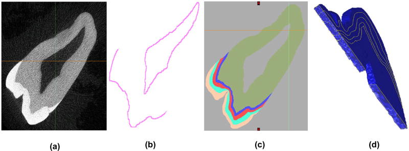
The model containing three layers of enamel, a DEJ layer and the dentin layer was first developed using a subset of 25 raw µCT Dicom images (Figure 1(a)) of a molar tooth, with the goal of segmenting each image of the set into three layers of enamel, namely the outer, middle and inner enamel (OE, ME and IE), a 100-µm thick DEJ and dentin (Figure 1(c)) region.
Figure 1.
(a) Raw black and white µCT Dicom image; (b) Obtaining the DEJ region via templating, dilation and subtraction; (c) Segmented 2D tooth image from multiple masking layers and image processing techniques; (d) Creation of a successful 3D volume-mesh.
The approximate size of each of the enamel regions were 0.25–0.4 mm for IE, 0.4–0.6 mm for ME and 0.4–0.5 mm for OE. The sizes of each of these regions were based on the indentation tests that we conducted to determine the elastic modulus of each region. Indentation tests were conducted at 30 µm from the outer edge (outer enamel), at 500 µm from the DEJ (middle enamel) and at 30 µm from the DEJ (inner enamel). Based on these locations and the resolution of the images in the modeling/segmentation software, we divided the enamel into these three regions. Figure 2 depicts the thickness of some of the regions of enamel and the DEJ. Using MIMICS®, each image was first segmented by histogram based on its value in Hounsfield Units (HU). The dentin area fell within a range of 5150–10,000 HU and the enamel from 10,001 to 12,297 (max) HU. The lower bound of 5150 was chosen with the aid of MIMICS to remove as much noise as possible while preserving much of the original signal. Following a series of complex and time consuming digital image processing operations, such as region-growing, gap-filling and 10-pixel closing, a nearly perfect set of images representing the dentin layer was obtained. Using a whole tooth mask as an outer boundary template, segmenting the DEJ (Figure 1(b)) proved to be a straightforward yet iterative process by dilating and subtracting the dentin layer, while paying close attention to the minimum width that would yield a working 3D model. This is due to the fact that as pixels are changed in one slice, they must be continuous with the next slice, otherwise discontinuity errors occur which affect 3D volume meshing.
Figure 2.
Thickness of the three different enamel regions (outer – brown, middle –bluish green and inner – red) along with the DEJ region (blue) depicted at two different locations.
A similar set of templating operations were performed for the enamel region of the tooth by increasing the dilation factor in order to segment the enamel into three regions – as seen in Figure 1(c). Finally, manual touchups were performed on the layers and masks as a tedious yet necessary detail. A final solid model STL file was generated that was imported to another software program – 3-Matic® – for meshing and finite element purposes.
The finite element model of the multi-region tooth segment was generated using 4 noded tetrahedral elements using 3-Matic. The STL files were imported from MIMICS to 3-Matic and using a seed length and some smoothing operations a volume mesh was generated as seen in Figure 1(d). The process of thresholding, model generation, smoothing and mesh generation between the two software had to be performed iteratively until a successful mesh was generated. The final mesh had 107,735 nodes and 580,604 four noded tetrahedral elements. Table 1 shows the number of nodes and elements in each region. It should be noted that due to nodes shared between each region the sum total of the number of nodes in each region is greater than the total number of nodes in the mesh.
Table 1.
Number of nodes and elements in each region.
| Region | Number of nodes | Number of elements |
|---|---|---|
| Outer enamel | 26,911 | 67,971 |
| Middle enamel | 15,447 | 69,416 |
| Inner enamel | 12,168 | 58,856 |
| Dentin enamel junction | 26,906 | 48,744 |
| Dentin | 62,869 | 335,613 |
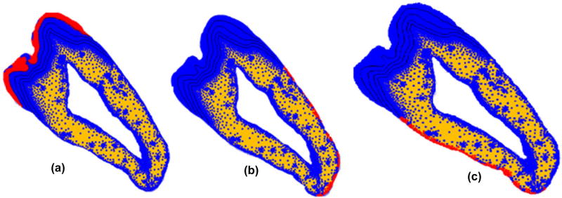
Three boundary conditions on different surfaces have been applied to the model to act as a support to the 2D tooth structure. In order to simulate the rigid support provided by the mandible to the tooth structure the nodes on the two dentin outer boundaries were constrained from moving as shown in Figure 3. In addition, the entire tooth model was restrained from moving out of plane by restraining motion of all the surface nodes in the transverse direction.
Figure 3.
Boundary conditions applied on outer enamel and dentine boundaries on both sides. (a) fixed transverse displacement applied on enamel; (b) and (c) fixed displacement on the outer surface of dentin.
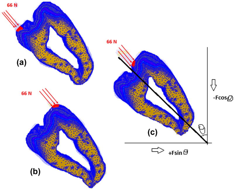
Loading of the model was based on published values (Dejak et al. 2003). The loads were applied on the surface of the outer enamel at three locations – lingual cusp, buccal cusp and buccal occlusal – as shown in Figure 4. The areas where these loads were applied were identified after the mesh building phase in 3-Matic and the set of nodes representing these areas were transferred to the finite element program FeBio (Maas et al. 2012) through an input file. Load was applied on these nodes at the three load locations. The load acts on approximately 145 nodes at each of these locations. The required equivalent static force F acting on the outer enamel surface is taken to be 66 N at each load location (Dejak et al. 2003), which is equally distributed among the 145 nodes. The forces on the tooth act perpendicular to the outer enamel surface. Hence, to simulate the perpendicular force, two forces Fcosθ and Fsinθ are applied along the coordinate axis that results in an equivalent force of F perpendicular to the surface of the tooth, where θ is the angle made by the perpendicular force with the coordinate axis. Figure 4 shows the directions of various forces and the resulting force F. Figure 4 also depicts the loading of the model at lingual cusp, buccal cusp and buccal occlusal positions, respectively, with a force of 66 N at each location. The angle between the tooth axis and the vertical θ = 45°. Hence the magnitude of forces are 46.6 N along the x and y axes in the positive and negative directions respectively at all the three locations.
Figure 4.
Static load locations (a) Lingual cusp, (b) buccal cusp, and (c) buccal occlusal. The resultant axes are the same for all the three loads.
Experimental data used for FE model simulation
The mechanical property data of individual teeth such as elastic modulus, density and Poisson’s ratio play an important role in defining the material to be used for each layer of the model in simulating the tooth structure. Each of the regions in the tooth model was defined in terms of their elastic mechanical properties. The values of elastic modulus are different for each layer while the Poisson’s ratio and density of the tooth were assumed to be constant for layers of teeth. The density of the tooth used to build the model was 2.8e-009 ton/mm3. The values for the elastic modulus were taken from a previous study determined using the nano indentation technique for an in vitro specimen (Reed et al. 2015) and an in vivo specimen. The values of the elastic modulus and the standard deviation of each layer are tabulated in Table 2. Since we did not measure the elastic modulus of the DEJ directly, we have assigned it a value higher than that of dentin based on studies by Marshall et al. (2001). The value of Poisson’s ratio used in this study is also shown in Table 2.
Table 2.
Mechanical properties of materials used in model.
| Elastic modulus of control/ non-radiated (GPa) |
Elastic modulus of in vitro (70 Gy) (GPa) |
Elastic modulus of in vivo (>60 Gy) (GPa) |
Poisson’s ratio | |
|---|---|---|---|---|
| Outer enamel | 107.75 ± 12.73 | 109.73 ± 14.03 | 99.68 ± 24.78 ↓ | 0.3 |
| Middle enamel | 84.82 ± 7.97 | 89.65 ± 9.9 | 90.22 ± 17.07 ↑ | 0.3 |
| Inner enamel | 76.39 ± 11.46 | 86.07 ± 9.71 | 87.76 ± 18.28 ↑ | 0.3 |
| Dentin | 24.35 ± 3.41 | 24.35 ± 3.14 | 24.35 ± 3.14 | 0.3 |
| Dentin Enamel Junction | 30 | 30 | 30 | 0.3 |
Note: The arrows indicate the decrease or increase in elastic modulus for in vivo teeth compared to control/non-radiated teeth.
We used a public domain finite element program FeBio (Maas and Weiss 2008; Maas et al. 2012), which is being used for various biological finite element simulations. PreView was used to generate the FE model details, FeBio was used for analysis and results were analyzed using PostView. Both PreView and PostView are a part of the FeBio suite.
FE model simulation cases
Two types of simulations were performed as follows:
First, we compared the FE analysis results between the control, in vivo, and in vitro models to observe changes in the stress contour patterns and magnitudes of principal tensile stress and maximum shear stress.
Second, we performed a parametric study by systematically changing the elastic modulus of each of the enamel layers. The changes were made to the in vivo model and comparisons were done between the original control model values (designated as the Control) and the modified values model (designated as the Modified in vivo). In each case we increased/decreased the elastic modulus, as indicated by the arrows in Table 2, until we observed clear changes in the stress values and patterns. The results are presented for the elastic modulus value at which changes in stress contour patterns were visually observed.
The following cases were studied for the parametric study:
Case A: Decrease in elastic modulus of outer enamel of in vivo model at intervals of 4 GPa. This study was done as we had observed a decrease in the modulus value between the control and in vivo specimen.
Case B: Increase in elastic modulus of the middle enamel at intervals of 5 GPa due to the observed increase in the elastic modulus value between the control and in vivo specimen.
Case C: Increase in elastic modulus of the inner enamel at intervals of 5 GPa due to the observed increase in the elastic modulus value from control to in vivo specimen.
Case D: Decrease in elastic modulus of the DEJ at intervals of 5 GPa.
In all the simulations we have quantified the stress by considering an identical region of interest (ROI) in the two models being compared and calculating the average stress in all the elements in the ROI using the Trackview tool of PostView.
Results
Control vs. in vivo vs. in vitro
By visually observing the stress contours in Postview, critical regions in each of the layers were identified and the shear stress and principal tensile stress were quantified. Table 3 shows a comparison of stresses and their locations. In each case the values in bold letters represent an increase in the stress values that were observed in the respective regions as compared to the non-radiated control.
Table 3.
Table showing the average ± standard deviation in each ROI among the three groups according to the location of highest stress.
| Principal tensile stress (MPa)* |
Maximum shear stress (MPa) |
Location | |
|---|---|---|---|
| No radiation (Control) | 2.40 ± 0.82 | 46.04 ± 10.63 | Outer enamel–buccal occlusal |
| In vivo radiation | 2.56 ± 1.27 | 45.32 ± 10.34 | |
| In vitro radiation | 2.35 ± 0.83 | 44.92 ± 10.81 | |
| No radiation (Control) | 10.75 ± 2.14 | 58.57 ± 1.60 | Middle enamel |
| In vivo radiation | 12.49 ± 2.45 | 59.33 ± 1.62 | |
| In vitro radiation | 10.09 ± 1.91 | 58.27 ± 1.83 | |
| No Radiation (Control) | 8.44 ± 1.57 | 57.83 ± 2.07 | Inner enamel cervical |
| In vivo radiation | 9.97 ± 1.32 | 58.18 ± 1.53 | |
| In vitro radiation | 8.15 ± 0.97 | 57.81 ± 1.82 | |
| No radiation (Control) | 7.98 ± 1.46 | 50.39 ± 1.59 | Dentin-enamel junction |
| In vivo radiation | 8.29 ± 1.19 | 49.24 ± 2.11 | |
| In vitro radiation | 9.72 ± 2.01 | 52.66 ± 2.54 |
Observed increases bolded as compared to the no radiation (control) group.; The location of the region of interest where the highest stresses were observed is shown in the last column for each group.
Simulation results
Outer enamel
There were no observed differences in the either the maximum shear or tensile stress between the three experimental groups for outer enamel region.
Middle enamel
For the middle enamel region, there was an increase in the principal tensile stress between the control (10.75 ± 2.14 MPa) and the in vivo model (12.49 ± 2.45 MPa). No significant changes in shear stress magnitude was observed.
Inner enamel
An increase was also observed for the inner enamel cervical region on the lingual side of in vivo radiated teeth (9.97 ± 1.32 MPa) as compared to control non-radiated teeth (8.44 ± 1.57 MPa). Once again no changes in shear stress magnitude was observed.
DEJ
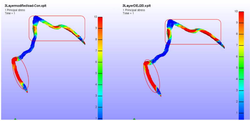
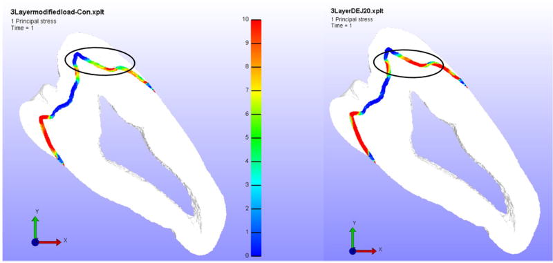
Similarly, the DEJ showed an increase in principal tensile stress of less than ten percent between the control and in vivo radiated teeth with no variation in shear stress. However, the area of red intensity was higher. Figure 5 shows the first principal stress contour in the DEJ for the control and in vivo radiated tooth models and the differences in the intensity and the extent of the red areas (which represent the highest stress values) can be observed in the figure.
Figure 5.
Left – Control Model Principal Stress in DEJ, Right – In vivo model Principal Stress in DEJ.
Simulation results based on a parametric study
In this section the results of the parametric study are presented. It was assumed that radiation of teeth would result in modulus change patterns as observed in the experimental study and indicated by the arrows in Table 2.
Case A (Reducing outer enamel modulus)
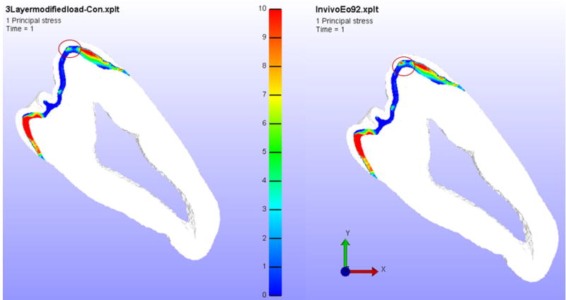
The models were run using the in vivo model values of the elastic modulus and changing only the original outer enamel elastic modulus value (99.68 GPa) to 96 GPa and 92 GPa. The stress patterns in every layer were compared with the respective layer of the base control model. The results for the 96 GPa model were not much different from the default control model. However, for the 92 GPa value, the results were found to be different. For example, the stress patterns on middle enamel at the buccal cusp area where the load is applied increased when compared to the control model values. The quantified value of tensile stresses for the control model in this area are 9.22 ± 3.02 MPa, whereas for the 92 GPa model it was 10.27 ± 4.38 MPa. Figure 6 shows the first principal stress contour of the two models highlighting the differences in the stress patterns. Hence, it could be observed that the principal tensile stress near the buccal cusp region of the middle enamel increases as the elastic modulus of the outer enamel goes down after radiation.
Figure 6.
Principal tensile stress in middle enamel when elastic modulus of the outer enamel is reduced to 92 GPa.
Left – Control Model Principal Stress, Right – In vivo model Principal Stress. The circle shows the region of interest used for comparison of stress values.
Case B (Increasing middle enamel elastic modulus)
For the second case the elastic modulus of the middle enamel was increased at intervals of 5 GPa starting from 90 GPa. The in vivo model had an elastic modulus value of 90.22 GPa for middle enamel. The first observed clear changes in stress patterns were found at a middle enamel elastic modulus of 105 GPa at the edges of dentin-enamel junction near inner enamel. The first principal tensile stress in the inner enamel layer of this model is 2.2 times more than that of control model. There is also an increase in maximum shear stress of 7.0 MPa compared to the control model in the middle enamel region.
Case C (Increasing inner enamel elastic modulus)
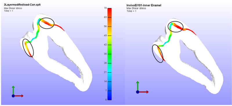
In third case, the elastic modulus of inner enamel was increased in increments from an initial value of 90 GPa. Figure 7 shows the comparison of shear stresses in inner enamel between the control and modified elastic modulus model. The maximum shear/tensile stress in the control model was 53.05 ± 1.01/19.45 ± 5.95 MPa while the model with inner enamel elastic modulus of 101 GPa was 50.16 ± 0.68/20.52 ± 11.7 MPa. No major change was observed in this case.
Figure 7.
Maximum shear stress in inner enamel when elastic modulus of inner enamel is increased to 101 GPa.
Left – Control Model Shear Stress, Right – In vivo model Shear Stress. The circle shows the region of interest used for comparison of stress values.
Case D (Reducing DEJ elastic modulus)
In the last case, the differences in stress patterns between the control and in vivo model by reducing elastic modulus of the DEJ are compared. The parametric study was conducted with a DEJ elastic modulus of 20 GPa. The differences were observed in principal stress of dentin enamel junction and outer enamel. The first principal tensile stresses in DEJ of control model were (6.37 ± 3.70) MPa and for the decreased DEJ elastic modulus case, it was found to increase to (10.14 ± 4.58) MPa. Figure 8 shows the comparison of the first principal stress in the DEJ. Here, a difference of 3.2 MPa in the principal tensile stress between the control and the reduced elastic modulus model was observed.
Figure 8.
Principal stress in DEJ when elastic modulus of DEJ is reduced to 20 GPa from 30 GPa.
Left – Control Model Principal Stress, Right – In vivo model Principal Stress. The circle shows the region of interest used for comparison of stress values.
Discussion
The present study has explored the mechanical response of irradiated molar teeth subjected to loading in order to study the delamination of enamel from the teeth of patients following oral cancer radiotherapy. Specifically, our finite element analysis has explored the effects of radiation-induced changes in the elastic modulus of enamel on the magnitude of stress response of a molar tooth subjected to occlusal loading. Difficulties in obtaining whole in vivo radiated teeth for this analysis were due to the small number available extracted teeth from oral cancer patients post-radiotherapy and to the damaging effects of radiation, e.g. delamination. As a result, a group of extracted non-carious whole third molar teeth were subjected to simulated oral cancer therapeutic radiation in vitro. Specifically, teeth extracted from non-radiated patients were split into two groups; namely the control (non-irradiated) and in vitro irradiated groups. The in vitro irradiated teeth were subjected to a radiation dosage equivalent to that given to an oral cancer patient, but under controlled laboratory conditions. One of the limitations of the in vitro radiation method was that – at best it is a simulated mouth environment.
Since, to the best of our knowledge, there have been no studies on the strength of teeth following actual or simulated oral cancer radiotherapy, we have limited our studies to the elastic behavior of the tissue. Future studies will involve the determination of the strength of various regions of the tooth described in this paper both in tension and shear. Our first comparison of both the principal tensile and maximum shear stress of the control, in vivo and in vitro groups had interesting findings. There were no apparent differences in either the tensile and shear stress between the control and in vitro radiation group maybe due to the observation that in vitro radiation increased the elastic modulus of all regions of enamel. However, in contrast to the in vitro radiation, the in vivo radiated teeth had a decreased elastic modulus of the outer enamel region, while the middle and inner enamel region had a modulus value higher than those of in vitro radiated teeth. In comparing the stress values of control and in vivo radiated teeth, it was observed that the principal tensile stresses in the inner cervical region of the lingual side (9.97 MPa) were higher than the control (8.44 MPa) teeth. There are limited studies on the strength of different regions of non-irradiated teeth. Gianinni et al. (2004) reported that the ultimate tensile strength of healthy molar teeth to be 42.2 ± 11.9 MPa for the enamel parallel to the prismatic orientation and 11.5 ± 4.7 MPa for the enamel perpendicular to the prismatic orientation. It is interesting to note that the higher principal stress values observed in the in vivo model were approaching the reported ultimate tensile strength values of enamel perpendicular to prismatic orientation indicating a higher propensity of failure for the in vivo radiated teeth.
For the parametric study conducted by either increasing or decreasing the elastic modulus of the different regions, the principal tensile stress in the enamel near the buccal occlusal region was found to increase as the elastic modulus of the outer enamel decreased. In a similar manner, as the elastic modulus of the inner enamel is increased, a considerable change in the principal tensile stress (2.2-fold increase) was observed near the DEJ of the inner enamel. An increase in the principal stress in the DEJ was also observed as the elastic modulus of the DEJ was decreased. However, the increase in the tensile stress value from 6.37 to 10.14 MPa was not considered to be significant as it has been reported in Giannini et al. (2004) that the ultimate tensile strength of the DEJ is of the order of 46.9 ± 13.7 MPa, which is considerably higher than the observed stress values. Hence, this numerical study does not predict the failure at the DEJ. This observation also supports the observations of post-radiotherapy patient dentition failure that appears to be in the inner enamel region near the DEJ, but not specifically at the DEJ.
We acknowledge that building a full 3-D model would be beneficial. However, our reasons for the semi 2-D study (a thin section has been considered) and not a full 3-D study were twofold. The model is very difficult to build at the resolution of a few micrometers per element in a full 3-D form. We have presented here a novel micro-macro model that resolves the enamel into three layers in order to assign separate properties to each layer. Building such a 3-D model would be difficult considering that the enamel layer changes in dimension throughout the tooth.
Conclusions
A novel unexpected aspect of this experimental study, reported in our earlier publication (Reed et al. 2015), is that the elastic modulus of the outer region of enamel decreased in vivo while the middle and inner enamel moduli increased. In studying the property changes on the stresses in teeth it was found that the increased tensile stress associated with radiation-induced property changes within the inner enamel cervical region of in vivo radiated teeth may destabilize the enamel-dentin interface resulting in delamination of enamel near the DEJ. The DEJ also experienced higher stresses but these values were found to be within the ultimate tensile strength of the DEJ indicating the failure is predicted to start in the inner enamel region adjacent to the DEJ. Enamel is a brittle material and brittle materials tend to fail in tension prior to failing in shear which could be the reason there were no noticeable differences in the maximum shear stress in each of those layers.
Acknowledgments
We acknowledge the contributions of Steven Howard (Kansas City Cancer Centers; Kansas City, KS) for his assistance with simulated radiotherapy treatment of the tooth specimens.
Funding
This work was supported by the National Institute of Health – National Institute of Dental and Craniofacial Research [grant number R01DE21462].
Footnotes
Disclosure statement
No potential conflict of interest was reported by the authors.
References
- Dejak B, Młotkowski A, Romanowicz M. Finite element analysis of stresses in molars during clenching and mastication. J Prosthetic Dent. 2003;90:591–597. doi: 10.1016/j.prosdent.2003.08.009. [DOI] [PubMed] [Google Scholar]
- Fuentes V, Ceballos L, Osorio R, Toledano M, Carvalho RM, Pashley DH. Tensile strength and microhardness of treated human dentin. Dent Mater. 2004;20:522–529. doi: 10.1016/j.dental.2003.05.005. [DOI] [PubMed] [Google Scholar]
- Geng J-P, Tan KB, Liu G-R. Application of finite element analysis in implant dentistry: a review of the literature. J Prosthetic Dent. 2001;85:585–598. doi: 10.1067/mpr.2001.115251. [DOI] [PubMed] [Google Scholar]
- Giannini M, Soares CJ, de Carvalho RM. Ultimate tensile strength of tooth structures. Dent Mater. 2004;20:322–329. doi: 10.1016/S0109-5641(03)00110-6. [DOI] [PubMed] [Google Scholar]
- Gultekin BA, Gultekin P, Yalcin S. Application of Finite Element Analysis in Implant Dentistry. In: Farzad Ebrahimi., Dr, editor. Finite Element Analysis – New Trends and Developments. InTech; 2012. Available from: https://www.intechopen.com/books/finite-element-analysis-new-trends-and-developments/application-of-finite-element-analysis-in-implant-dentistry. [DOI] [Google Scholar]
- He L-H, Swain MV. Enamel – a functionally graded natural coating. J Dent. 2009;37:596–603. doi: 10.1016/j.jdent.2009.03.019. [DOI] [PubMed] [Google Scholar]
- Jansma J, Vissink A, Jongebloed W, Retief D. Johannes’s-Gravenmade E. Natural and induced radiation caries: a SEM study. Am J Dent. 1993;6:130–136. [PubMed] [Google Scholar]
- Jongebloed W, Gravenmade E, Retief D. Radiation caries. A review and SEM study. Am J Dent. 1988;1:139–146. [PubMed] [Google Scholar]
- Maas S, Weiss J. FEBio: finite elements for biomechanics. User’s manual, version 10. 2008 doi: 10.1115/1.4005694. Online publication. [DOI] [PMC free article] [PubMed] [Google Scholar]
- Maas SA, Ellis BJ, Ateshian GA, Weiss JA. FEBio: finite elements for biomechanics. J Biomech Eng. 2012;134:011005. doi: 10.1115/1.4005694. [DOI] [PMC free article] [PubMed] [Google Scholar]
- Mackerle J. Finite element modelling and simulations in dentistry: a bibliography 1990–2003. Comput Methods Biomech Biomed Eng. 2004;7:277–303. doi: 10.1080/10255840412331309243. [DOI] [PubMed] [Google Scholar]
- Marshall G, Balooch M, Gallagher R, Gansky S, Marshall S. Mechanical properties of the dentinoenamel junction: AFM studies of nanohardness, elastic modulus, and fracture. J Biomed Mater Res. 2001;54:87–95. doi: 10.1002/1097-4636(200101)54:1<87::aid-jbm10>3.0.co;2-z. [DOI] [PubMed] [Google Scholar]
- Petrie CS, Walker MP, Lu Y, Thiagarajan G. A preliminary three-dimensional finite element analysis of mandibular implant overdentures. Int J Prosthodont. 2013;27:70–72. doi: 10.11607/ijp.3425. [DOI] [PubMed] [Google Scholar]
- Reed R, Xu C, Liu Y, Gorski J, Wang Y, Walker M. Radiotherapy effect on nano-mechanical properties and chemical composition of enamel and dentine. Arch Oral Biol. 2015;60:690–697. doi: 10.1016/j.archoralbio.2015.02.020. [DOI] [PMC free article] [PubMed] [Google Scholar]
- Rees J. An investigation into the importance of the periodontal ligament and alveolar bone as supporting structures in finite element studies. J Oral Rehabil. 2001;28:425–432. doi: 10.1046/j.1365-2842.2001.00686.x. [DOI] [PubMed] [Google Scholar]
- Rilo B, Fernandez J, Da Silva L, Martinez Insua A, Santana U. Frontal-plane lateral border movements and chewing cycle characteristics. J Oral Rehabil. 2001;28:930–936. doi: 10.1046/j.1365-2842.2001.00723.x. [DOI] [PubMed] [Google Scholar]
- Vissink A, Jansma J, Spijkervet F, Burlage F, Coppes R. Oral sequelae of head and neck radiotherapy. Crit Rev Oral Biol Med. 2003;14:199–212. doi: 10.1177/154411130301400305. [DOI] [PubMed] [Google Scholar]
- Wakabayashi N, Ona M, Suzuki T, Igarashi Y. Nonlinear finite element analyses: advances and challenges in dental applications. J Dent. 2008;36:463–471. doi: 10.1016/j.jdent.2008.03.010. [DOI] [PubMed] [Google Scholar]
- Walker MP, Williams KB, Wichman B. Post-radiation dental index: development and reliability. Support Care Cancer. 2008;16:525–530. doi: 10.1007/s00520-007-0393-x. DOI: https://doi.org/10.1007/s00520-007-0393-x. [DOI] [PMC free article] [PubMed] [Google Scholar]
- Walker MP, Wichman B, Cheng A-L, Coster J, Williams KB. Impact of radiotherapy dose on dentition breakdown in head and neck cancer patients. Pract Radiat Oncol. 2011;1:142–148. doi: 10.1016/j.prro.2011.03.003. [DOI] [PMC free article] [PubMed] [Google Scholar]
- Xu C, Reed R, Gorski JP, Wang Y, Walker MP. The distribution of carbonate in enamel and its correlation with structure and mechanical properties. J Mater Sci. 2012;47:8035–8043. doi: 10.1007/s10853-012-6693-7. [DOI] [PMC free article] [PubMed] [Google Scholar]


