Abstract
This paper presents a novel miniature robotic endoscope that is small enough to pass through the Eustachian tube and provide visualization of the middle ear (ME). The device features a miniature bending tip previously conceived of as a small-scale robotic wrist that has been adapted to carry and aim a small chip-tip camera and fiber optic light sources. The motivation for trans-Eustachian tube ME inspection is to provide a natural-orifice-based route to the ME that does not require cutting or lifting the eardrum, as is currently required. In this paper, we first perform an analysis of the ME anatomy and use a computational design optimization platform to derive the kinematic requirements for endoscopic inspection of the ME through the Eustachian tube. Based on these requirements, we fabricate the proposed device and use it to demonstrate the feasibility of ME inspection in an anthropomorphic model, i.e. a 3D-printed ME phantom generated from patient image data. We show that our prototype provides > 74% visibility coverage of the sinus tympani, a region of the ME crucial for diagnosis, compared to an average of only 6.9% using a straight, non-articulated endoscope through the Eustachian Tube.
Index Terms: Medical Robots and Systems, Surgical Robotics, Steerable Catheters/Needles
I. INTRODUCTION
OVER the last decade, many robotic systems have been designed for minimally invasive medical applications [1]. These devices are typically deployed within the human body through small incisions or natural orifices, and are used in a variety of applications, e.g. to deliver treatment or conduct visual diagnosis. The natural orifice paradigm in particular is beneficial because it does not require damage to healthy tissue that might be in the way for the surgeon between the body entry point and the diagnostic/interventional site. One natural orifice that has not previously been used for a robotic natural orifice procedure is the Eustachian tube, which connects the nasopharynx to the middle ear (see path labeled ET in Fig. 1).
Fig. 1.
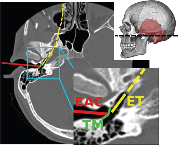
An axial Computed Tomography (CT) scan illustrating the traditional surgical approach to the middle ear through the External Auditory Canal (EAC), in which the eardrum (commonly referred to as Tympanic Membrane or TM in the medical literature) must be surgically incised. Also illustrated is the Eustachian Tube (ET) approach. Adapted from [2]. The dashed line through the skull indicates the position of the axial CT slice.
The motivation for inspection and therapy delivery in the middle ear (ME) comes from the high incidence of ME disease. ME disease is made up of a number of medical conditions that affect the internal structures of the ear, and are estimated to affect approximately 1 in 20 adults worldwide [3], [4], [5]. One condition of particular interest is cholesteatoma, a benign tumor that erodes hearing structures and causes hearing loss and recurrent infections. Treatment requires surgical removal, but cholesteatoma is challenging to diagnose since it occurs behind the eardrum and externally visible symptoms are non-specific [6]. As a result, cholesteatoma is often missed in primary care and diagnosed only later in the disease progress, typically after permanent damage to the internal hearing structures has occurred [6]. This condition is diagnosed in 7-12 per 100,000 people every year [7], [6], [8], [9].
To accurately diagnose cholesteatoma and other ME diseases, direct visualization is often necesary, which currently requires surgery. The eardrum is cut or lifted and either an endoscope or microscope is used to visualize internal ear structures [10] through the external auditory canal (path labeled EAC in Fig. 1). Importantly, many cholesteatoma patients (nearly 60% according to a recent study [11]) undergo a follow-up surgery approximately one year after the initial tumor removal. This surgery is required to inspect the ME and determine whether the cholesteatoma has recurred. Recurrence happens only about 25% of the time, meaning that many patients have a second surgery, but do not have recurrence [11], [12], [13]. The non-invasive approach through the Eustachian tube that we propose in this paper could save these patients a second surgery, and more broadly help physicians diagnose and treat a variety of ME diseases less invasively.
The feasibility of passing an endoscope through the Eustachian tube has been previously established by physicians [14], [15], [16], [17], but inspection usefulness has been limited by (1) lack of a bending tip on the small endoscopes used, and (2) the relatively low resolution provided by the flexible fiberscopes employed. Fortunately, two advancements have recently been made that address both these limitations. First, the latest generation of digital chip-based cameras provide approximately an order of magnitude higher resolution than similarly sized fiberscopes, i.e. over 100,000 pixels as in [18]. Next, an asymmetric flexure wrist design has recently been proposed in the robotics literature that enables a bendable tip to be created in a small diameter, with a large open lumen [19], [20]. Small diameter is required, because it has been established that devices must be smaller than 2 mm (and ideally as small as possible) to pass through the Eustachian tube [21]. In this paper, we combine the bending tip design of [19], [20] with a miniature chip-tip camera to create an endoscope suitable for ME inspection. This is the first report of an endoscope with controllable tip articulation designed to pass through the Eustachian tube.
Our study is structured as follows: we first derive general kinematic requirements for endoscope operation inside the ME. This analysis is performed by simulating the endoscopic inspection on three-dimensional models of the ME extracted from the CT scans of real patients. Using these models, we determine appropriate ranges for the endoscope diameter, length and required curvature. Later in the paper, we use these requirements to guide the design of the proposed device. Finally, we fabricate a prototype of the ME endoscope and demonstrate the feasibility of endoscopic ME inspection in an anthropomorphic phantom, matching the geometry of the human middle ear. Results of this study are discussed in the light of recent studies that have theorized the feasibility of ME endoscopy through the ET [2], [22].
II. KINEMATIC REQUIREMENTS
The anatomy of the ME is illustrated in Fig. 2. It consists of a main chamber, whose average volume in adults is 6.5 cm3 [25], and a number of smaller peripheral cavities. The main chamber contains the ossicles, i.e. a chain of bony structures responsible for the transmission of sound from the eardrum to the internal hearing organs (cochlea). The procedure we wish to enable consists of performing a visual inspection of the ME using an endoscope that is passed through the ET. We are particularly interested in enabling the inspection of the regions where disease is more likely to develop. Cholesteatoma, particularly recurrent cholesteatoma, is frequently found in the sinus tympani [26], a cavity that branches out of the main ME chamber (highlighted in Fig. 2). Because of its anatomic location, the sinus tympani (ST) cannot be reached from the ET via a straight-line path [2]. This is especially evident in Fig. 3(a), which shows the endoscope direction of insertion into the ME and the location of the ST. We hypothesize that an endoscope equipped with a steerable tip will enable a level of visual coverage that exceeds the performance of traditional straight scopes.
Fig. 2.
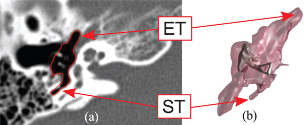
Anatomy of the middle ear: (a) Computed Tomography scan (axial view) where the ME volume has been segmented (red line) through the algorithm described in [23]; (b) 3D geometric model of the same ME generated with the marching cubes algorithm [24]. The external surface of the volume is semi-transparent to show the location of the ossicles, i.e. the chain of bony structures responsible for the transmission of sound to the internal hearing organs. The eustachian tube (ET) and sinus tympani (ST) are visible in the CT scan and the 3D model.
Fig. 3.
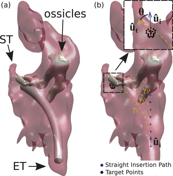
Simulated endoscopy of the Middle Ear. Figure (a) shows an example of endoscope insertion: the device shown here has a diameter of 1.40 mm and has been bent in such a way to point towards the sinus tympani (ST). Figure (b) illustrates how insertion paths γi are generated. The endoscope enters the ME following a straight path which coincides with the orientation of the Eustachian Tube (measured in the CT scan). After an initial straight motion of arbitrary length, the endoscope is bent along a constant curvature arc towards a target point. Target points are generated using a spherical grid in the proximity of the target anatomy. Insertion paths found to collide with the ossicles (like γ2 and γ3 in this example) are automatically detected and discarded. The endoscope final orientation defines the overall bending θ.
To determine the general kinematic requirements for endoscope inspection in the ME, we developed a software platform to simulate this procedure. The software uses 3D anatomical models of the ME generated from CT scans of real patients, and implements the ray-casting algorithm described in [2] to calculate the visible surface area of the ST during each simulated inspection. Repeated endoscope inspections were simulated to determine a suitable range for the endoscope length and curvature.
A. Geometric Computer Model of the Middle Ear
Models of ME geometry were created according to the methods described in [2]. These methods involve the use of statistical atlases, generated from high-resolution micro CT scans, to assist in the segmentation of ME structures from individual patient standard CT scans. For the following analyses, a total of six ME models were generated from patient CT scans.
B. Simulated Endoscope Insertion in the Middle Ear
Repeated insertion paths were generated as follows: a path γi consists of a straight section (represented by blue dots in Fig. 3b) when it is initially inserted into the ME, and a constant curvature section when it is bent towards the target point (dashed line in Fig. 3b). In all the simulation trials, the endoscope was navigated from the ET to the entrance of the ST cavity (selected manually in CT scan), as illustrated in Fig. 3a. To simulate different lengths and curvatures for the endoscope steerable section, we generated a high number of insertion paths – each time incrementing the length of the straight section by 0.10 mm – and leaving the length and curvature of the curved section free to vary (Fig. 3). Note that in these simulations we assumed an outside diameter of 1.4 mm for the endoscope. In Section III we will discuss the feasibility of creating a prototype at this diameter. We note that the optimal diameter to be used clinically is still an open question, but that non-steerable endoscopes with diameters as large as 2 mm have been passed through the Eustachian tube in patients previously [14], [15], [16], [17].
C. Calculation of Kinematic Requirements
1) Endoscope Curvature
For each of the six ME models, we determined the insertion path that maximizes visual coverage of the ST and calculated the associated bending angle (i.e. θ, as shown in the call-out in Fig. 3b) and length of the curved section. Results are summarized in Table I. This calculation was performed using the ray-casting technique described in [2], and assuming an endoscope field of view (FoV) of 90° (i.e. the same FoV available in many commercially-available endoscopic imaging systems, e.g. [17], [18]). Bending angles range between 47.8° and 74.8°, therefore any design offering at least 74.8° of angular deflection will be suitable for all the ME specimens considered here.
TABLE I.
Endoscope Curvature Requirements and Corresponding Percent Visualization of the Sinus Tympani
| Patient No. | Curved Section Length (mm) | Bending Angle θ (°) | Visualization (%) |
|---|---|---|---|
| 1 | 15.57 | 52.0 | 71.6 |
| 2 | 11.33 | 47.8 | 85.7 |
| 3 | 13.48 | 54.0 | 72.1 |
| 4 | 13.47 | 59.8 | 72.9 |
| 5 | 12.90 | 52.8 | 62.5 |
| 6 | 13.17 | 74.8 | 59.1 |
2) Endoscope Tip Length
The curved section lengths reported in Table I provide an indication on the overall length of the endoscope steerable tip. We conducted another round of simulated insertion trials, this time limiting the maximum length of the endoscope curved section to 13.45 mm. This value was determined as the mean between the upper and lower values observed earlier (i.e. 15.57 and 11.33 mm). Table II reports the ST visualization that was achieved under this condition. These results present negligible differences with respect to the optimal visualization values calculated earlier, therefore suggesting that 13.45 mm is an adequate length for the endoscope steerable tip.
TABLE II.
Percent Visualization of the Sinus Tympani with a 13.45 mm curved section
| Patient No. | Visualization (%) |
|---|---|
| 1 | 67.8 |
| 2 | 85.7 |
| 3 | 72.0 |
| 4 | 72.9 |
| 5 | 62.5 |
| 6 | 59.1 |
III. ENDOSCOPE DESIGN AND FABRICATION
Based on the requirements derived in the previous section, here we present the design of the proposed ME endoscope. The device concept is shown in Fig. 4: it consists of a flexible Nitinol sheath with a chip-tip camera mounted at its tip. The asymmetric notches on the body of the device enable unidirectional bending (θ), which combined with translation (z) and rotation (φ) enable the device to reach virtually any point in 3D. In the following, we first describe the components of the device, and then report on its fabrication.
Fig. 4.
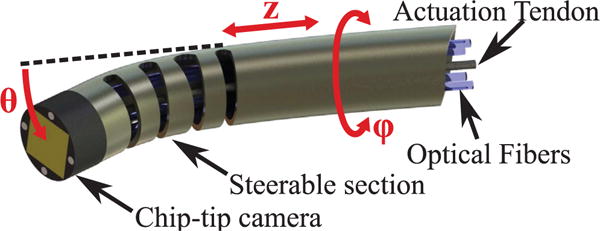
CAD rendering of the proposed miniature robotic endoscope concept. A chip-tip camera is placed on the distal tip of the steerable section. The robotic endoscope has three DoFs. The steerable section is a Nitinol tube containing cut-outs that cause it to bend (θ) as a single tendon attached to the tip is pulled. It can also translate (z) and rotate (ϕ) along its axis. The actuation tendon and camera wiring pass through the interior of the tube.
A. Chip-Tip Camera
The chip-tip camera is the minnieScope™-XS (Enable Inc., Redwood City, CA), which has a diameter of 1.4 mm and a length of 2 mm. This CMOS-based videoscope offers a resolution of 400×400, a field of view of 90°, and a frame rate of 30 frames per second. Four optical fibers are integrated on the tip to provide illumination. The camera is connected to an external video processing unit through a flexible cable (diameter: 1.32 mm) that contains both electrical connections and the optical fibers used for illumination.
B. Bending Mechanism
The distal tip of the Nitinol tube is notched, creating a steerable section that can be controllably curved using a thin tendon. This mechanism was originally described in [19], and is particularly suited for our current purposes since (1) it provides a large open lumen for the camera and optical fibers used for illumination, (2) it can be easiliy miniaturized below 2 mm (as small as 0.46 mm was demonstrated in [20]), and (3) it has been shown to enable tighter radii of curvature than other similar designs, e.g. [27], [28], [29].
Bending control is enabled by a model that maps the tendon displacement, Δl, to the resulting bending angle. This model is described in [19], [20], but is briefly reviewed here for completeness. For a single cutout, such a mapping can be found using the tube inner radius ri and the chord function (refer to Fig. 5),
| (1) |
| (2) |
where Δl varies with the actuated length of the tendon within the cutout, t. θ is the bending angle of a single section and κ is the curvature about the wrist center axis (red dashed line in Fig. 5) and is given by
| (3) |
Here, represents the position of the neutral bending plane, i.e. the region of the tube that experiences no longitudinal strain during bending. Such a location depends on the depth of the cut w, as wells as the inner and outer radii of the tube ri and ro. It can be straightforwardly calculated using the equations given in [20]. Control of wrist bending requires the inversion of (2), however this has no analytic inverse. A simple linear approximation can be derived assuming a small bending angle:
| (4) |
Note that the spacing between the cutouts, x, does not affect the bending angle but impacts the overall length of the steerable section.
Fig. 5.
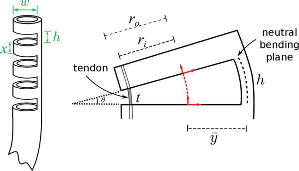
Flexure wrist concept: a number of cutouts are made in the body of a Nitinol tube, creating a compliant region that can be bent using a single tendon. Parameters w and h represent the cutout width and height, while x is the distance between two consecutive cutouts. These parameters plus the total number of cutouts n, determine the maximum bending angle of the wrist. The right figure illustrates the deflection of a single cutout element when the tendon is pulled. The variables ro and ri are the outer and inner diameter of the Nitinol tube, respectively. The angular deflection of a single section, θ, is determined by the height, h, the tendon length within the cutout, t, and the distance between the center of the tube and the neutral bending plane, .
C. Endoscope fabrication
We fabricated the prototype shown in Fig. 6, which was made from a Nitinol tube with an OD of 1.8 mm and an inside diameter (ID) of 1.6 mm. This was the closest available stock size to the the 1.4 mm diameter minnieScope™ at the time of purchase. Note that in a clinical version of this design, we would remove the outer rubber cladding from the minnieScope™ and replace it with Nitinol. Thus, in principle the OD of the nitinol bending section could be as small as the current OD of the minnieScope™, i.e. 1.4 mm in diameter. However, custom sized nitinol tubing is expensive for initial lab prototyping, so we proceeded with the closest available stock size, and also did not remove the minnieScope cladding so as not to damage the scope accidentally during first proof of concept experiments. Also, since the endoscope was slightly larger than what we anticipate the final clinical version to be, we scaled up the middle ear phantom used for the validation of the device, as we shall see in the next section. The scaling factor was 1.25, which is approximately the same factor with which the endoscope was scaled due to use of stock nitinol tube sizes.
Fig. 6.

Endoscope Prototype. There are eight cutouts in a segment of Nitinol Tube having inner diameter (ID) of 1.60 mm and outer diameter (OD) of 1.80 mm. The cutouts have a height of 1 mm and a width of 1.60 mm. In this picture, the chip-tip camera is located at the leftmost end of the tube. A Nitinol wire (diameter = 0.22 mm) is looped around the most distal cutout to provide actuation.
Cutouts were created in the Nitinol tube using the CNC fabrication process described in [20]. The height h and distance between cutouts x were set to 1 mm (refer to Fig. 5), while the width w was set to 1.60 mm. These parameters were determined using the mechanics model presented in [20], and in such a way to limit the maximum strain during bending below 8% and avoid plastic deformation of the device (Nitinol is typically quoted at 8–10% recoverable strain). We created a total of 8 cutouts, resulting in a steerable section of 15 mm, and an overall tip length of 17 mm (a 2 mm section was left at the beginning of the tube to accomodate the chip-tip camera). The number of cutouts was selected based on the ideal tip length derived earlier in section II (13.45 mm), the scaling factor of the prototype (1.25x), and the closest approximation to that value that could be created with x + h = 2 mm increments.
A 0.22 mm Nitinol tendon was used for wrist actuation. While in principle this tendon could be welded in place, to simplify fabrication it was looped around the distal cutout so that two lengths of wire run through the tube to its base. Given the tolerance between the camera and Nitinol outer sheath, the wire thickness creates a tight fit, so that the camera is held in place with a simple press fit.
We calibrated our device by applying tendon displacements in increments of Δl = 1 mm and measuring the corresponding bending angle. Results are shown in Fig. 7. A linear regression was found to model the behavior of the wrist between 0° and 160°, with a root-mean-square error (RMSE) of 3.71°. Our prototype thereby satisfies and exceeds the bending requirements previously derived in simulation (74.8°).
Fig. 7.
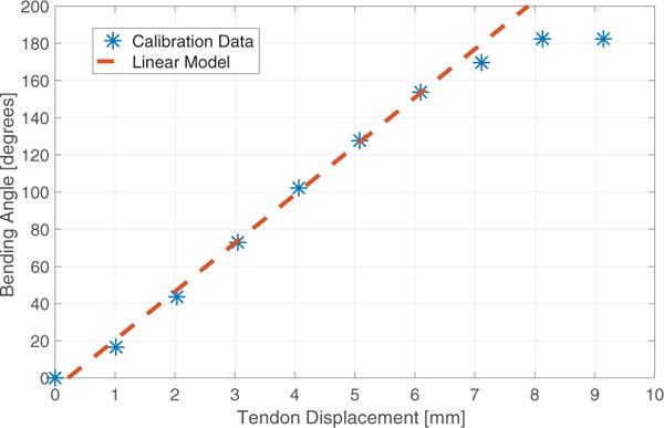
Experimental calibration of the prototype.
IV. PHANTOM EXPERIMENT
The endoscope prototype was tested using a custom manufactured ME phantom. The phantom was made in plastic via stereolithography 3D printing (Proto Labs, Inc., Maple Plain, MN, USA; material: Accura 60, high resolution build). The phantom shape was based on a 3D mesh reproducing real human anatomy and was generated from Computed Tomography (CT) images [2], [22], as illustrated in Fig. 8. The size was scaled up 1.25× to compensate for the increased size of the endoscope prototype. The phantom was made with fiducial points (see reference divots in Fig. 8) that enable the location of the robot to be registered to both the phantom and the CT scan space.
Fig. 8.
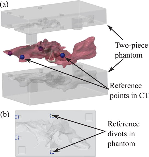
3D printed phantom used in the experiment. (a) Exploded view of two-piece phantom and mesh of ME used to generate the phantom geometry. Reference points (shown as blue spheres) were selected around ME in the CT scan to be used for registration with the phantom. (b) Planar view of bottom side of phantom. Divots corresponding to the reference points in the CT scan are outlined in blue dashed lines. These divots can be localized in the video of the experimental insertion to align the video with the CT scan.
We conducted an experiment that consisted of deploying the robot into the ME phantom via the Eustachian tube and then maneuvering it via both insertion and bending of the tip. The robot was registered to the fiducial markers using camera images (as those shown in Fig. 9), which measured both the position and orientation of the endoscope tip. These photographs are then registered to the CT scan from which the phantom was generated and used to calculate the surface area viewable by the robot, During insertion, the robot was steered towards the sinus tympani (ST), to assess the attainability of the visualization rates achieved in simulation (Table I).
Fig. 9.
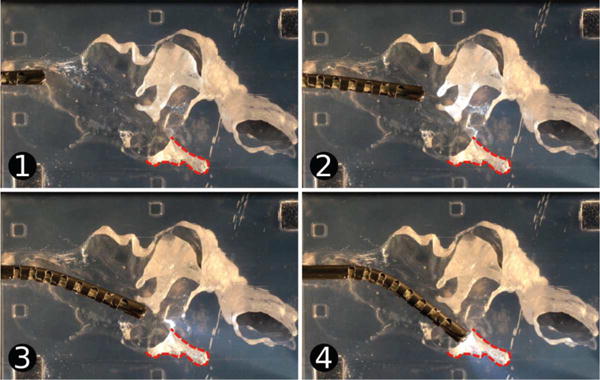
Testing of the endoscope tip. The device was inserted into the ME phantom and pointed towards the sinus tympani (ST), which is outlined on the images. Images (1) through (4) show the endoscope position over time.
A Computer Numeric Control (CNC) machine was used to align the endoscope with the phantom and the endoscope was positioned initially at the Eustachian tube entrance to the ME. The endoscope was then advanced into the ME phantom towards the ST using a single axis of the CNC machine and the steerable tip was curved by pulling the actuation tendon using a manually-operated positioning slider (Unislide, Velmex Inc., Bloomfield, NY) with 0.025 mm resolution. A video of the insertion was recorded and several frames were extracted for analysis (Fig. 9). The centroids of the fiducial points in the video image were localized and the image was registered to the CT scan using them. The position and orientation of the endoscope tip were also determined in the image and then transformed to the CT scan coordinate system using the reference fiducial locations.
The position and orientation of the endoscope tip in the CT scan throughout the trajectory were used to calculate the visualization coverage of the ME. Using the same ray-casting technique described in [2], [22], we calculated which elements of the ME mesh could be viewed without obstruction by the chip-tip camera at each point along the insertion trajectory, and then aggregated this data to determine the overall coverage. A camera Field of View (FoV) of 90° was used in the calculation, since this is the FoV of the chip-tip camera used in the prototype.
Fig. 10 illustrates the estimated visualization coverage of the ST realized during the experiment. The device was able to visualize the ST entrance and some parts of the inner cavity, with the exception of the deepest areas. The percent visualized surface was 74.1%.
Fig. 10.
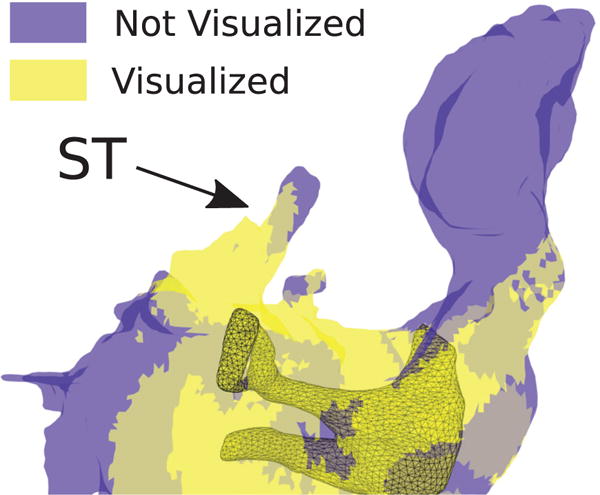
Estimation of ME areas which were visible (yellow) and not visible (blue) during the phantom experiment. We estimated an 74.1% visual coverage of the ST during the experiment.
V. DISCUSSION
The visualization coverage achieved in the phantom experiment represents a substantial increase over what is possible with current instrumentation. In a recent study, Zhang et al. have determined that only 6.9% of the ST would be visibile with a straight scope positioned at the entrance of the ET [2]. The availability of tip articulation enables the exploration of difficult-to-reach cavities like the ST, facilitating the surveillance of cholesteatoma and other ME diseases. The results presented here demonstrate for the first time the feasibility of ME endoscopy through the ET.
The results of the kinematic requirements study presented in section II indicate that the maximum visual coverage that can be achieved in the ST varies by patient and depends on the specific ST anatomy. Further qualitative review of the simulation results along with the CT scans revealed that two important factors are the depth and morphology of the ST cavity. Most cavities can be simply inspected with a 1-DoF steerable design, especially if the endoscope can achieve a good visual alignment with the bottom of the ST, as in the case of Fig. 9. On the other hand, some patients might present a particularly deep ST, or a complex morphology that makes visualization difficult. A recent study by Marchioni et al. [30] reviewed the anatomical variations of the ST in a total of 296 ears, and found that only a limited number of cases (4.4%) present deep/complex ST shapes. These results suggest that the design presented in this paper will be suitable for use in the vast majority of the patient population. Further work will be required to identify an appropriate endoscope design for those patients who present a deep/complex ST anatomy. One option we will explore is the use of additional DoFs, i.e. the creation of additional compliant sections in the body of the robot, each presenting a different orientation and separate actuation. In principle, this would permit the creation of more complex curvilinear shapes, thereby enhancing the overall dexterity of the device. We hypothesize that having an additional DoF at the robot’s tip will enable a better alignment between the device and the ST orientation, resulting in a more comprehensive visual coverage.
Future work will focus on the automatic control of the endoscope movements and the development of a human-robot interface. It is also worth noting that this device might be possible to deploy as a non-robotic hand-held tool, as well. We envision the creation of a robotic system that incorporates image guidance and position tracking to implement automatic exploration of the ME internal volume. Such a system will integrate preoperative medical imaging (CT scans), and automatically conduct an exploration of the ME, focusing on the region of interests indicated by the surgeon in a preoperative plan. Our hypothesis is that this approach will facilitate comprehensive visual coverage of the ME, as opposed to simple manual teleoperation.
To validate the proposed device and procedure in a more realistic clinical setting, we plan to conduct cadaver studies. One important aspect that will have to be investigated is the quality of the endoscopic images provided by the chip-tip camera. The camera included in the current version of our endoscope offers a resolution of 160,000 pixels [18], which exceeds the resolution of prior endoscopes that have been used for middle ear procedures, e.g. the 1.6 mm endoscope used in [17] which offered 6,000 pixels. It seems intuitive that higher resolution will enable better image quality, although further studies will be needed to assess the diagnostic value of the images returned in a clinical study.
VI. CONCLUSIONS
The miniature robotic endoscope proposed in this paper is small enough to be passed through the Eustachian tube, and its steerable tip enables it to achieve a significantly higher visual coverage of the middle ear than what would be achievable with current instrumentation. In the future, this device is expected to significantly simplify the diagnosis and treatment of patients with ME disease.
The same device can in principle be used in other medical applications where the target anatomy cannot be reached by a simple straight path, and the size of the endoscope must be as small as possible due to anatomic constraints. Potential applications include constrained anatomical environments like the brain, biliary ducts, and urinary system.
Future work will be directed towards clinical validation of the proposed device. This will require the creation of a control interface for the physician, as well as cadaver studies to further assess the diagnostic capabilities of the device. Furthermore, we will use computational simulation to further explore the design parameter space. The dexterity of the device can be further enhanced through additional DoFs, i.e. by creating a cutouts at various angles about the shaft centerline. This will enable the device to achieve more complex shapes, e.g. S shapes, which may be beneficial in increasing visualization further in the middle ear and/or facilitating applications in other areas of the body.
Acknowledgments
The authors are grateful to Trevor L. Bruns and Dr. Philip J. Swaney, who supported the fabrication of the endoscope prototype.
This paper was recommended for publication by Editor K. Masamune upon evaluation of the Associate Editor and Reviewers’ comments. This work was funded in part by award number IIS-1054331 from the National Science Foundation (NSF), and in part award numbers R01 DC012593 and R01 DC008408 from the National Institutes of Health (NIH). The content is solely the responsibility of the authors and does not necessarily represent the official views of the NSF or the NIH.
Contributor Information
Loris Fichera, Department of Mechanical Engineering, Vanderbilt University, Nashville, TN 37235 USA.
Neal P. Dillon, Department of Mechanical Engineering, Vanderbilt University, Nashville, TN 37235 USA
Dongqing Zhang, Department of Electrical Engineering and Computer Science, Vanderbilt University, Nashville, TN 37235 USA.
Isuru S. Godage, Department of Mechanical Engineering, Vanderbilt University, Nashville, TN 37235 USA
Michael A. Siebold, Department of Electrical Engineering and Computer Science, Vanderbilt University, Nashville, TN 37235 USA
Bryan I. Hartley, Department of Radiology, Vanderbilt University Medical Center, Nashville, TN 37232 USA
Jack H. Noble, Department of Electrical Engineering and Computer Science, Vanderbilt University, Nashville, TN 37235 USA
Paul T. Russell, III, Department of Otolaryngology, Vanderbilt University Medical Center, Nashville, TN 37232 USA.
Robert F. Labadie, Department of Otolaryngology, Vanderbilt University Medical Center, Nashville, TN 37232 USA
Robert J. Webster, III, Department of Mechanical Engineering, Vanderbilt University, Nashville, TN 37235 USA.
References
- 1.Burgner-Kahrs J, Rucker DC, Choset H. Continuum robots for medical applications: A survey. IEEE Transactions on Robotics. 2015;31(6):1261–1280. [Google Scholar]
- 2.Zhang D, Bennett ML, Labadie RF, Noble JH. Simulation of trans-nasal endoscopy of the middle ear for visualization of cholesteatoma. 2015 IEEE 12th International Symposium on Biomedical Imaging (ISBI) 2015 Apr;:1415–1418. [Google Scholar]
- 3.Wallis S, Atkinson H, Coatesworth AP. Chronic otitis media. Postgraduate Medicine. 2015;127(4):391–395. doi: 10.1080/00325481.2015.1027133. [DOI] [PubMed] [Google Scholar]
- 4.Browning GG, Gatehouse S. The prevalence of middle ear disease in the adult british population. Clinical Otolaryngology & Allied Sciences. 1992;17(4):317–321. doi: 10.1111/j.1365-2273.1992.tb01004.x. [DOI] [PubMed] [Google Scholar]
- 5.Hannula S, Bloigu R, Majamaa K, Sorri M, Mki-Torkko E. Ear diseases and other risk factors for hearing impairment among adults: an epidemiological study. International Journal of Audiology. 2012;51(11):833–840. doi: 10.3109/14992027.2012.707334. [DOI] [PubMed] [Google Scholar]
- 6.Bhutta MF, Williamson IG, Sudhoff HH. Cholesteatoma. BMJ. 2011;342 doi: 10.1136/bmj.d1088. [DOI] [PubMed] [Google Scholar]
- 7.Kemppainen HO, Puhakka HJ, Laippala PJ, Sipilä MM, Manninen MP, Karma PH. Epidemiology and aetiology of middle ear cholesteatoma. Acta oto-laryngologica. 1999;119(5):568–572. doi: 10.1080/00016489950180801. [DOI] [PubMed] [Google Scholar]
- 8.Djurhuus BD, Faber CE, Skytthe A, et al. Decreasing incidence rate for surgically treated middle ear cholesteatoma in Denmark 1977–2007. Danish Medical Bulletin. 2010;57(10):A4186. [PubMed] [Google Scholar]
- 9.Aquino JEAP, Filho NAC, Aquino JNP. Epidemiology of middle ear and mastoid cholesteatomas: study of 1146 cases. Brazilian Journal of Otorhinolaryngology. 2011;77(3):341–347. doi: 10.1590/S1808-86942011000300012. [DOI] [PMC free article] [PubMed] [Google Scholar]
- 10.Poe DS, Rebeiz EE, Pankratov MM, Shapshay SM. Transtympanic endoscopy of the middle ear. The Laryngoscope. 1992;102(9):993–996. doi: 10.1288/00005537-199209000-00007. [DOI] [PubMed] [Google Scholar]
- 11.Crowson MG, Ramprasad VH, Chapurin N, Cunningham CD, Kaylie DM. Cost analysis and outcomes of a second-look tympanoplasty-mastoidectomy strategy for cholesteatoma. The Laryn-goscope. 2016;126(11):2574–2579. doi: 10.1002/lary.25941. [DOI] [PubMed] [Google Scholar]
- 12.Syms MJ, Luxford WM. Management of cholesteatoma: status of the canal wall. The Laryngoscope. 2003;113(3):443–448. doi: 10.1097/00005537-200303000-00010. [DOI] [PubMed] [Google Scholar]
- 13.Neudert M, Lailach S, Lasurashvili N, Kemper M, Beleites T, Zahnert T. Cholesteatoma recidivism: comparison of three different surgical techniques. Otology & Neurotology. 2014;35(10):1801–1808. doi: 10.1097/MAO.0000000000000484. [DOI] [PubMed] [Google Scholar]
- 14.Di Martino E, Walther LE, Westhofen M. Endoscopic examination of the eustachian tube: a step-by-step approach. Otology & Neurotology. 2005;26(6):1112–1117. doi: 10.1097/01.mao.0000176175.71894.98. [DOI] [PubMed] [Google Scholar]
- 15.Klug C, Fabinyi B, Tschabitscher M. Endoscopy of the middle ear through the eustachian tube: anatomic possibilities and limitations. Otology & Neurotology. 1999;20(3):299–303. [PubMed] [Google Scholar]
- 16.Linstrom CJ, Silverman CA, Rosen A, Meiteles LZ. Eustachian tube endoscopy in patients with chronic ear disease. The Laryngoscope. 2000;110(11):1884–1889. doi: 10.1097/00005537-200011000-00022. [DOI] [PubMed] [Google Scholar]
- 17.Todt I, Seidl R, Ernst A. A new minimally invasive method for the transtubal, microendoscopic application of fluids to the middle ear. Minimally Invasive Therapy & Allied Technologies. 2008;17(5):300–302. doi: 10.1080/13645700802274786. [DOI] [PubMed] [Google Scholar]
- 18.Enable Inc. http://www.enableimaging.com/technology.html, Accessed: Jan 21, 2017.
- 19.York PA, Swaney PJ, Gilbert HB, Webster RJ. A wrist for needle-sized surgical robots. 2015 IEEE International Conference on Robotics and Automation (ICRA) 2015 May;:1776–1781. doi: 10.1109/ICRA.2015.7139428. [DOI] [PMC free article] [PubMed] [Google Scholar]
- 20.Swaney PJ, York PA, Gilbert HB, Burgner-Kahrs J, Webster RJ. Design, fabrication, and testing of a needle-sized wrist for surgical instruments. Journal of Medical Devices. 2017;11(1):014 501–014. 501–9. doi: 10.1115/1.4034575. [DOI] [PMC free article] [PubMed] [Google Scholar]
- 21.Manes RP, Kutz JW, Isaacson B, Batra PS. Technical feasibility of endoscopic eustachian tube catheter placement: A cadaveric analysis. American Journal of Rhinology and Allergy. 2013;27(4):314–316. doi: 10.2500/ajra.2013.27.3914. [DOI] [PubMed] [Google Scholar]
- 22.Bennett ML, Zhang D, Labadie RF, Noble JH. Comparison of middle ear visualization with endoscopy and microscopy. Otology & Neurotology. 2016;37(4):362–366. doi: 10.1097/MAO.0000000000000988. [DOI] [PubMed] [Google Scholar]
- 23.Noble JH, Dawant BM, Warren FM, Labadie RF. Automatic identification and 3-d rendering of temporal bone anatomy. Otology & Neurotology. 2009;30(4):436. doi: 10.1097/MAO.0b013e31819e61ed. [DOI] [PMC free article] [PubMed] [Google Scholar]
- 24.Lorensen WE, Cline HE. ACM Siggraph Computer Graphics. 4. Vol. 21. ACM; 1987. Marching cubes: A high resolution 3d surface construction algorithm; pp. 163–169. [Google Scholar]
- 25.Molvaer O, Vallersnes F, Kringlebotn M. The size of the middle ear and the mastoid air cell: System measured by an acoustic method. Acta oto-laryngologica. 1978;85(1–6):24–32. doi: 10.3109/00016487809121419. [DOI] [PubMed] [Google Scholar]
- 26.McRackan TR, Abdellatif WM, Wanna GB, Rivas A, Gupta N, Dietrich MS, Haynes DS. Evaluation of second look procedures for pediatric cholesteatomas. Otolaryngology–Head and Neck Surgery. 2011;145(1):154–160. doi: 10.1177/0194599810396624. [DOI] [PubMed] [Google Scholar]
- 27.Kutzer MDM, Segreti SM, Brown CY, Armand M, Taylor RH, Mears SC. Design of a new cable-driven manipulator with a large open lumen: Preliminary applications in the minimally-invasive removal of osteolysis. 2011 IEEE International Conference on Robotics and Automation. 2011 May;:2913–2920. [Google Scholar]
- 28.Fischer H, Vogel B, Pfleging W, Besser H. Flexible distal tip made of nitinol (NiTi) for a steerable endoscopic camera system. Materials Science and Engineering: A. 1999;273:780–783. [Google Scholar]
- 29.Liu J, Hall B, Frecker M, Reutzel EW. Compliant articulation structure using superelastic nitinol. Smart Materials and Structures. 2013;22(9):094018. [Google Scholar]
- 30.Marchioni D, Valerini S, Mattioli F, Alicandri-Ciufelli M, Pre-sutti L. Radiological assessment of the sinus tympani: temporal bone hrct analyses and surgically related findings. Surgical and Radiologic Anatomy. 2015;37(4):385–392. doi: 10.1007/s00276-014-1366-7. [DOI] [PubMed] [Google Scholar]


