Abstract
Wireless Power Transfer (WPT) and wireless data communication are both important problems of research with various applications, especially in medicine. However, these two problems are usually studied separately. In this work, we present a joint study of both problems. Most medical electronic devices, such as smart implants, must have both a power supply to allow continuous operation and a communication link to pass information. Traditionally, separate wireless channels for power transfer and communication are utilized, which complicate the system structure, increase power consumption and make device miniaturization difficult. A more effective approach is to use a single wireless link with both functions of delivering power and passing information. We present a design of such a wireless link in which power and data travel in opposite directions. In order to aggressively miniaturize the implant and reduce power consumption, we eliminate the traditional multi-bit Analog-to-Digital Converter (ADC), digital memory and data transmission circuits all together. Instead, we use a pulse stream, which is obtained from the original biological signal, by a sigma-delta converter and an edge detector, to alter the load properties of the WPT channel. The resulting WPT signal is synchronized with the load changes therefore requiring no memory elements to record inter-pulse intervals. We take advantage of the high sensitivity of the resonant WPT to the load change, and the system dynamic response is used to transfer each pulse. The transient time of the WPT system is analyzed using the coupling mode theory (CMT). Our experimental results show that the memoryless approach works well for both power delivery and data transmission, providing a new wireless platform for the design of future miniaturized medical implants.
Keywords: Wireless power transfer, data communication, load modulation, transient process, coupling mode theory
Introduction
The Wireless Power Transfer (WPT) technology can extend the lifetime of the battery operated device and eliminate the complications due to cable connection. With an advanced concept of strongly coupled magnetic resonances, which was proposed in 2007[1, 2], the WPT has become a promising method to address the problem of power delivery in highly constrained environment. One of the most popular application areas of WPT is wirelessly powering biosensors or implants within the bodies of humans or animals [3–5]. The non-invasive solution has attracted a great deal of attention in diverse applications, such as electric stimulators for muscles and neural tissues, endoscopic capsules, cardiac pacemakers, and cochlear implants [6–14].
One additional challenge associated with medical implants is the transmission of data acquired by these devices to the outside of the biological body[4, 5]. The methods of data transmission usually involve an independent wireless data link. A typical data link consists of an extra coil operated using inductive coupling [15–19]. Such a system must deal with the problem of the cross-coupling between the data and power links. Another method uses a pair of radio frequency (RF) antenna to transmit data and an inductive link for WPT [20–23]. Such a hybrid system reduces cross-interferences but is more complicated and size/weight demanding.
Unifying the WPT and communication channels into a single channel would be a desirable approach because it simplifies the hardware structure. Previous studies use an on-off switch to change the load of an inductive power link for data transmission [9, 19, 24, 25], and it can be considered as a load shift keying (LSK) technique where the modulation is achieved by shifting the switch based on the data stream [24]. In addition, each switching state (on or off) must be held for a relatively long period of time to ensure the system to reach a steady state. This approach has serious drawbacks that the data rate is low, and the on/off states affect the power transfer efficiency due to frequent mistuning. Beside the problem in the RF transmitter, many systems rely on the use of digitally sampled signals to perform data communication [14, 19, 20, 23, 26]. In order to digitize biological signals, a multi-bit analog-to-digital converter (ADC), a digital memory to hold the samples, and a digital control circuit (e.g., a microcontroller) to manage data flow are required. These basic hardware components demand both space and power supply. An alternative approach to the transmission of both data and power is to use frequency modulation topology with an oscillation circuit [9]. Such an approach was successfully applied to a class of biological signals, such as the signals produced by impedance and pH sensors. However, this approach may be unsuitable in measuring and transmitting the signal with sharp variations, such as the electromyogram (EMG) and with electrocardiogram (ECG).
In this work, we propose a unified wireless power and data communication strategy. Instead of converting the analog biological signal to digital samples with a fixed number of bits per value, we convert the analog signal to a series of pulses with varying inter-pulse intervals using a sigma-delta (Σ-Δ) convertor. To shorten the pulse width, we use a smart delay and an exclusive OR (XOR) operator to extract the edge of the signal to form a new stream of pulses. These pulses are used to modify a capacitive load of the power link, and no storage is required for the pulse series. Moreover, the transient response of the WPT system is employed to implement pulses transmission. The advantages of this novel approach are three-fold. Firstly, the sensor no longer needs a multi-bit ADC, a data buffer/memory, a digital control, and even a digital clock. As a result, the circuit for signal acquisition is simplified greatly. Secondly, the width of each pulse can be minimized and the detuning time can be reduced by the transient process in the WPT, rather than the steady-state process. Consequently, the loss of the power transfer is decreased and the data rate is increased since denser pulses can be utilized. Thirdly, as the results of reduction in power consumption and elimination of separate communication circuits, the adverse effects of heat generation within tissue are reduced.
The remainder of this paper is organized as follows: the system architecture and function are described in Section II; the method for analyzing the unified power/data system is explained in Section III with an analysis using the coupled mode theory (CMT); an experimental set-up with load capacitive modulation of the pulses is demonstrated in Section IV; and conclusions are drawn in Section V.
1 Methods and system architecture
1.1 Wireless power and communication with pulse modulation
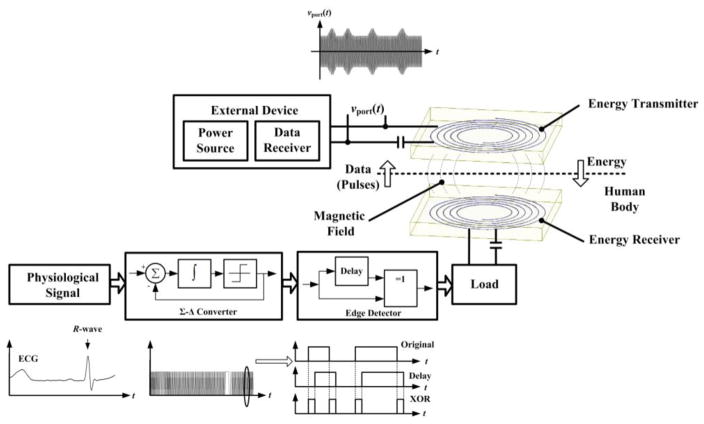
Our design of the unified wireless power and data link is conceptually shown in Fig. 1. Energy is delivered from the outside of the human body to a receiver within the implant by magnetic induction. The data acquired by the sensor is transmitted in the backward direction (from the inside to the outside of the body) by modulating the load on the energy receiver. The biological signal (here we assume, without loss of generality, to be an ECG or EEG signal) is converted to a stream of pulses by a sigma-delta (Σ-Δ) converter and an edge detector. The Σ-Δ converter, which is composed of an integrator and a one-bit quantize. It has been shown that this type of converter has the ability to acquire a wide range of biomedical signals and is well suited for biotelemetry systems [27, 28].
Fig. 1.
Unified wireless data transmission and WPT link based on Σ-Δ conversion and load modulation.
Both the signal’s bandwidth and the post-processing method govern the sampling frequency and the sampling period of the Σ-Δ converter. For the ECG and EEG, the frequency components of interest are usually bellow 150 Hz [29] [30]. Without loss of generality, let us assume that the highest frequency of interest is 30 Hz and the oversampling ratio (OSR) for the Σ-Δ converter is 256. Then, the sampling period is approximately 10−4 s and the pulse-width of the Σ-Δ must be integer multiples of the sampling period. This pulse-width could be adjusted (shortened) by increasing the OSR; however, the pulse-width may still be too wide to accurately resolve sharp changes in the signal, such as the change that takes place around the R-wave in the ECG, as shown in Fig. 1. If the load is modulated directly by pulses from the Σ-Δ converter, the efficiency of WPT system will be reduced because the resonant system for power transfer will be detuned during the switching-on period.
In order to obtain a shorter pulse-width without losing information, we propose an edge detection operation in which the output signal of the Σ-Δ converter is delayed by a small amount. The delayed output is then operated upon by an XOR logic with respect to the original signal to extract the edges and form a new stream of pulses. These pulses with a uniform pulse-width accurately mark the positions of the original pulses, and the stream is then utilized to modulate the load. For the magnetic resonant based WPT system, there is a high-sensitivity of the power transfer performance to load variation and mistuning. This was previously considered as a negative phenomenon to be avoided in WPT system design [2]. In our case, however, we take advantage of this sensitivity and use it to pass information. More details will be provided in Section III.
Using our strategy, the complete information of the analog signal is now contained within the distances between adjacent pulses (intervals) rather than the values of the pulses. Instead of storing these distances, we use the pulses to alter the load of the wireless power transfer (WPT) channel directly. These pulses can be considered as ‘flags’ to mark the distances and detected at the power transmitter side (or outside of the human body) where power and space are much less constrained. As a result, the alteration signals at both transmitter and receiver sides are time-synchronized (with a constant delay).
1.2 Circuit structure of WPT system
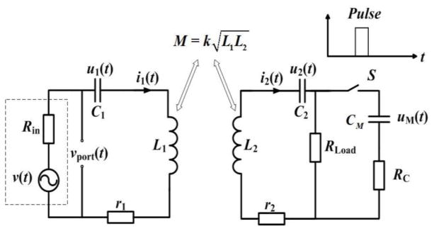
The equivalent circuit of the WPT system in Fig. 1 is shown in Fig. 2.
Fig. 2.
Equivalent circuit of the WPT system (depicted in Fig. 1) with a modulation switch.
In this circuit, two LC tanks linked magnetically by a mutual inductance M which is related to the coupling factor k and the inductors (L1, L2) in the coils of the transmitter and receiver. L1 and L2, with parasitic resistances (r1, r2), are tuned by capacitors (C1, C2). The system is excited by a source on the power transmitter side. This source is composed of a sinusoidal voltage v(t) operating at an angular frequency ω. Ideally, the output impedance Rin matches the total impedance of the power transfer system. On the power receiver side, switch S controls the parallel connection of CM and RC with load RLoad, where RC represents the parasitic resistance of CM, and the switch is controlled by the arriving pulses from the edge detector.
Both LC tanks at the transmitter and receiver sides are tuned to the same frequency. This enabled the WPT system to operate at the resonant mode in which the optimal power transmission is achieved [1, 2]. In this case:
| (1) |
Under the impedance matching condition, an application of the Kirchhoff’s voltage law (KVL) at the steady-state yields:
| (2) |
Moreover, the voltage of the source output port vport(t) is considered to be the output variable of the data transmission system and is used to detect the activity of the switch within the implant. The disturbances at the receiver reflect this variable.
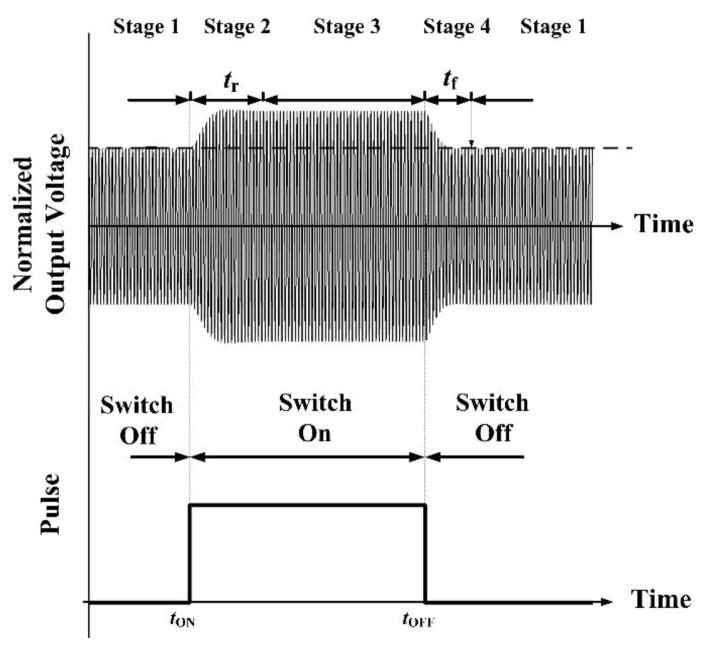
Fig. 3 shows a typical response at the power transmitter side of the WPT system. The amplitude modulation of vport(t) is the result of capacitive load modulation within the implant. This dynamic process can be divided into four stages: two steady states at switch-on and switch-off (stages 1 and 3), and two transient states at tON and tOFF (stages 2 and 4). Stage 1 is a normal state for the WPT system with a resonant LC circuit, and the maximum efficiency is obtained at this state. Stage 3 is affected by the capacitive load which inevitably causes a certain loss because the power receiver is detuned. In this research we aim to shorten or eliminate this stage with a short pulse-width.
Fig. 3.
Transient and steady states in the power transmission signal vport(t) (upper panel) as the result of load modulation pulse within the implant (lower panel).
The rising time tr of stage 2 and the falling time tf of stage 4 are significant when stage 3 is shortened aggressively a. Thus, tr constrains the achievable width of the pulse, and tf affects the intervals between adjacent pulses. Therefore, a thorough analysis of these times is important.
2 Transient Time Analysis
The phasor theory and the impedance analysis are widely used to investigate the magnetically coupled circuits (as the one shown in Fig. 2), and they are useful tools to describe the steady state response to the sinusoidal excitation. However, in our case, the dynamic process is of our interest. Using classic circuit theory, like KVL, to analyze the system will establish a higher order equations and the solutions, but they will be too complicated to study the transient time. Therefore, we use the coupled mode theory (CMT) to analyze our system within the time domain. For simplicity, we assume the parameters of the coils are identical, i.e., L1=L2=L, C1=C2=C and r1=r2=r.
2.1 Transient time at the switch shifting
According to CMT, the modes of the resonant system are defined as [31]:
| (3) |
The voltages u1(t), u2(t) and the currents i1(t), i2(t) are all defined in Fig. 2. The energy in the LC circuit is |a|2=W, so that the physical meaning of the modes are justified. Using the CMT, the system can be described by the following differential equations:
| (4) |
where the coupling coefficient κ is defined as κ= ω0M/2[L1L2]0.5=ω0k/2, and Γ1 and Γ2, respectively, are decay factors representing the losses in transmission and receiver (to be discussed in the next subsection). The coupling equations (4) well describes the energy exchanging between the two resonant coils [32, 33]. In our case, we focus on the dynamic process of WPT system. Therefore, the driving item (F(t), 0)T for the steady analysis is not taken into account in (4). In order to obtain the transient time during the modulation, the eigenvalues of the state matrix in (4) are calculated as:
| (5) |
According to the standard form of solution to (4) based on eigenvalues in (5), the mode is decaying with a rate of exp(−(Γ1+Γ2)t/2). Therefore the time constant of the exponential decay of the system is obtained:
| (6) |
Generally speaking, when the amplitude is decayed by e−4 (in terms of the amplitude ratio), the system can be considered to have reached the steady state, namely:
| (7) |
Therefore, the transient time induced by the switching activity can be approximated by:
| (8) |
The transient time determines the possible width of the pulse and interval. Eq.(8) indicates that the transient time is inversely proportional to the sum of Γ1 and Γ2. The loss Γ1 at the transmitter side is kept constant (r/2L) in the modulation process. However, the loss Γ2 at the receiver side varies when the modulation capacitor CM is connected to the circuit. In order to study the rising time, we use the equivalent circuit to obtain the loss Γ2 when the switch is on.
2.2 Equivalent resistance on the receiver side during modulation
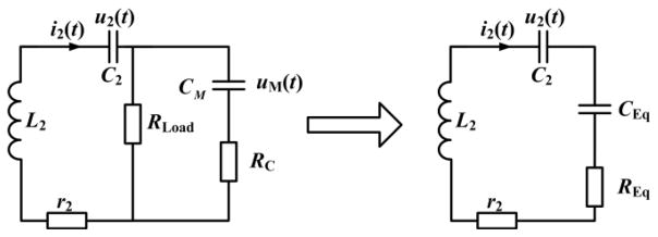
To simplify the analysis of Γ2, we use an approximate approach. When CM is connected due to the pulse arrival, the load RLoad with CM and RC can be equivalent to an impedance with CEq and REq, as shown in Fig. 4.
Fig. 4.
The equivalent network when the switch is on.
| (9) |
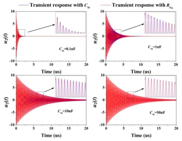
The resistive part REq determines the loss since Γ2= (REq +r2)/2L2. On the other hand, the capacitive part CEq specifies a frequency shift at the receiver, which is undesirable in terms of power transmission. Generally speaking, a large CEq can be obtained when CM is sufficiently small, and the circuit model can thus be simplified without considering CEq. To examine the effect of the equivalent approach, we perform a computer simulation model corresponding to Fig. 4 and CEq is eliminated. The results are shown in Fig. 5 with CM= [0.1, 1, 10, 50] nF, and the RLoad is set as 50 ohm. The almost completely overlap between the red curve (original model) and blue curve (simplified model) indicates the validity of the simplification.
Fig. 5.
Comparison of transient responses between original and simplified model. The initial values of i2 and u2 were set to 0 A and 10 V respectively.
Then, REq, along with r and L, can closely characterized the loss on the power receiver side. Therefore, the load modulation process by the switch can be considered as a change of loss, namely:
| (10) |
and the rising and falling time are:
| (11) |
The widths of pulse and interval are constrained by the falling and rising times. In other words, the system needs at leaset tr+tf to transfer a single pulse. Therefore, the maximal achievable data speed is also determined by (11). There are two major factors influencing the data speed. Firstly, the transient time is limited by Γ1 and Γ2:
| (12) |
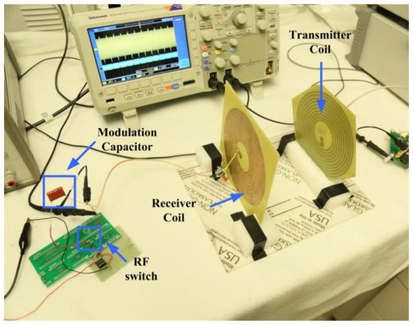
which are inversely proportional to the quality factors. It has been found that high Q factors on both transmitter and receiver are desired, because they can improve the power transfer efficiency[1]. However, as demonstrated in (11) and (12), high Q factors will increase the transient time, and thus limit the data speed. Secondly, a larger value of modulation capacitor CM will cause a longer transient time, as shown in Fig. 6, because the equivalent resistance REq is directly influenced by CM, namely:
| (13) |
Fig. 6.
The prototype of a WPT system with load modulation.
The rising time tr can be reduced by choosing a smaller CM, and thus the data speed can be improved.
3 Experiment and Analysis
3.1 Experimental set-up
Based on the analysis presented previously, a prototype of MR-WPT system with a load modulation was constructed. Our system setup is shown in Fig. 6, which implements the circuit block diagram in Fig. 1.
The coils were fabricated on a printed circuit board (PCB). The parameters of the coils are listed in TABLE I. These parameters were measured using a network analyser (VNA 2180, Array Solutions). The resonant frequency of the resonant system was tuned to 6.78 MHz which was one of the ISM frequency bands designated for unlicensed operations. A 50 Ω resistor was used to simulate the load of the WPT system. The distance between the transmission and reception coils was 145 mm, and the coupling factor k was approximately 0.08.
TABLE I.
Coil parameters of the experimental system (at 6.78MHz)
| Transmitter coil | Receiver coil | |
|---|---|---|
| Inductance L | 9.88 uH | 9.85 uH |
| Tuning capacitor C | 53.9 pF | 56.1 pF |
| Parasitic resistance r | 5.02Ω | 5.33Ω |
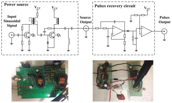
At the transmitter side, a two-stage RF amplifier was used to supply power to the WPT system. The structure is shown in in the left side of Fig. 7. The input signal came from a function generator, and the DC source VCC was set to 15V. A T-type network with two capacitors and an inductor was used as a matching network. Meanwhile, the voltage at the output port was the equivalent voltage vport for subsequent pulse detection, as shown in the previous analysis, to provide data communication from the inside to the outside of the human body. A circuit which is shown in the right side of Fig. 7 was built to recover the pulses from vport and it was set up with a 2nd-order low-pass active filter, an envelope detector and a voltage comparator.
Fig. 7.
Top Row: schematics of the RF amplifier (left) and pulses recovery circuit (right); Bottom Row: Implementations of the RF amplifier (left) and pulses recovery circuit (right).
On the power receiver side, a commercial RF switch (rf2436, RF Micro Devices, Inc.) was controlled by the pulses from the output of the edge detector. This switching enabled CM, which is a 1.58nF film capacitor, to modulate the load, as shown in Fig. 2. The parasitic resistance of CM was measured to be 0.17 Ω at 6.78MHz.
3.2 Pulses transmission
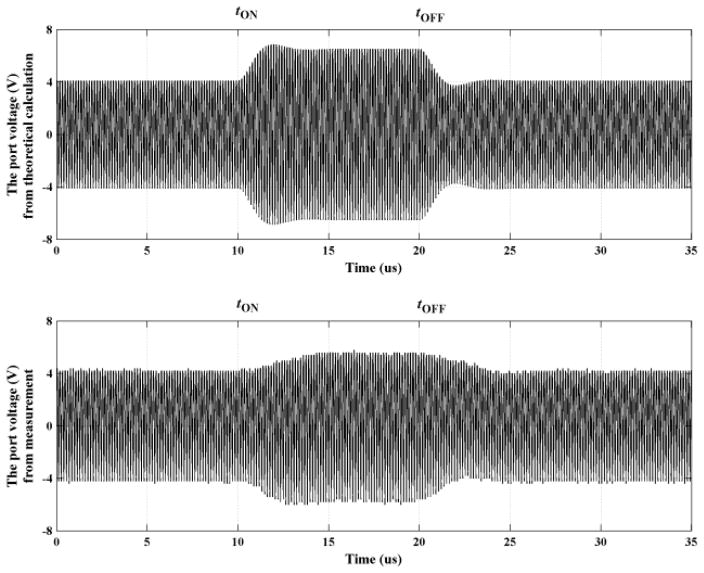
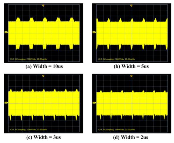
In order to investigate the effect of the pulse width on the signal transmission of the system, various pulse widths were chosen to test the modulation performance, as shown in Fig. 9. We measured vport (see the left side of Fig. 2) using a Tektronix MSO2012B oscilloscope which clearly showed the transient responses (pulses) as the data communication signal transmitted from the power receiver side. Although the waveform was not perfectly matched with the theoretical value due to the non-linear parasitic elements in the switch, as shown in Fig. 9, its effect on data communication is minimal. The transient time from switch-off to switch-on was about 3.93 us, according to Eq.(8).
Fig. 9.
A single response (pulse-width 10us) obtained by theoretical calculation (top) and experiment (bottom).
When the pulse width was 10us, the system had a sufficient time to reach a steady state, as shown in Fig. 9(a). In contrast, when the pulse width was 3us, there was not enough time for the transient process to complete. Nonetheless, the waveform variation was still evident to allow data communication by recovering the transmitted pulse. As the pulse width decreased further to 2us, the variation in waveform became less distinct, as shown in Fig. 9(d). The pulse width was set as 3us in the following section.
3.3 ECG signal transmission
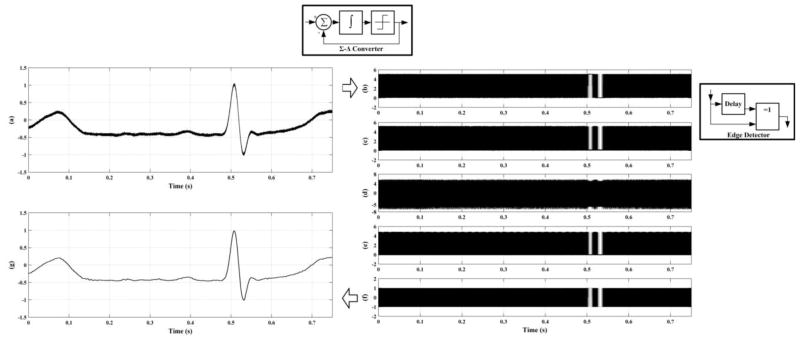
A typical ECG signal was used to test the function of data communication, as shown in Fig. 10(a). The signal was converted to a sequence of pulses using the sigma-delta converter in our experimental system. Then, the edges of the pulses were extracted at the power receiver side. The processes of sigma-delta conversion and edges extraction were preformed by National Instrument (NI, USB-6251). Considering the main frequency component was 30Hz, we sampled the signal with 512 × 30Hz = 15.36kHz sampling rate, and the data rate of sigma-delta output was also 15.36kbps due to the synchronous transmission. The pulses were recovered from vport with the circuit shown in Fig. 7.
Fig. 10.
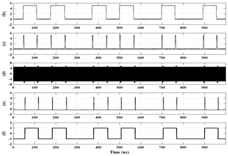
Experimental results of signal transmission and recovery. A typical ECG signal (a) was converted to a series of pulses (b) and (e), sent through the WPT channel, and reconstructed (g). Trace (d) shows the responses to vport. Trace (e) shows pulses recovered at the external side using the circuit shown in Fig. 7. Trace (f) shows the recovered sigma-delta signal.
The responses shown in Fig. 10(d) kept the positions of the pulses which recorded the information of the original ECG signal. These responses are sufficient to recover the pulses with the circuit shown in Fig. 7. Note that the recovered pulses in Fig. 10(e) had several microseconds of delay with respect to the original signal. These pulses were further converted to the sigma-delta signal as shown in Fig. 10(f) using an edge triggered flip-flop. With a Cascaded Integrator-Comb (CIC) filter, the ECG signal was reconstructed at the power transmitter site (external to the human body for the case of medical implants).
In order to investigate the impact of signal transmission on the power channel, the evaluation of the power transfer efficiency is needed. Due to the dynamic process in the modulation, the efficiency cannot be calculated using general method, which uses the voltage amplitudes of both power source at power transmitter side and load at the power receiver side. One method of measuring the efficiency is acquiring all the data of the entire signal period, but it requires extremely large data storage and loss accuracy in sampling the sinusoid carrier voltages.
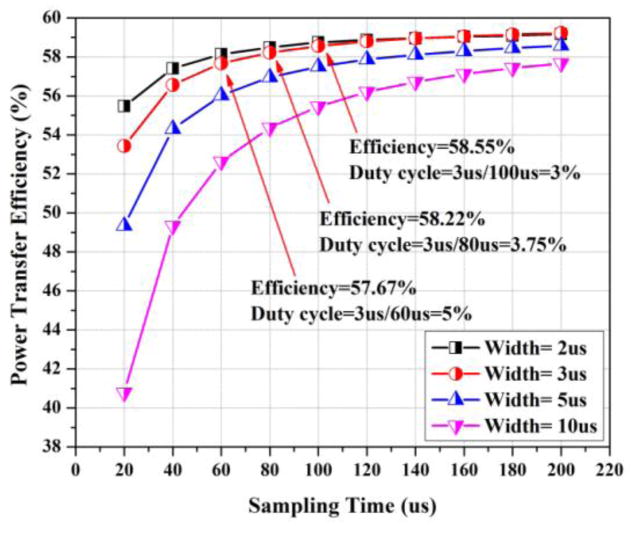
In practice, we selected a single pulse in certain sampling times to represent features of pulse stream and measure the corresponding efficiency to estimate the efficiency of the modulated waveform. We conducted a comparison from different pulse-widths and duty cycles, and the results are shown in Fig. 12. The pulse-width was set as 2us, 3us, 5us, and 10us. In Fig. 12, the duty cycles corresponding to the pulse-width=3us are also marked.
Fig. 12.
The power transfer efficiency is affected by different pulse-widths and duty cycles, which are calculated by (Width)/(Sampling Time).
In Fig. 10(b), the sampling period of sigma-delta convertor was 1/15.36kHz=65.10us. Because the pulse-width was set as 3us, the maximum duty cycle in transmitting the ECG signal is 3us/65.10us=4.61%. Meanwhile, in the entire ECG period, the averaging duty cycle of pulse stream was 3.06%. According to the results shown in Fig. 12, we can estimate that the overall power transfer efficiency should be more than 57.67% and slightly lower than 58.55%. The power transfer efficiency without any modulation (stage 1 in Fig. 3) was 59.54%, therefore, the efficiency would drop less than 2% with signal transmission. Our study indicates that the disturbances of modulation to the power transfer are relatively small due to the advantage of the transient process in WPT system.
4 Conclusion
In this study, a new strategy for both wireless power and data delivery has been presented for sensor or control systems that use Magnetic Resonance based Wireless Power Transfer (MR-WPT). We have conducted a sigma-delta converter and an edge detector to convert the input biomedical signal into pulses with the same pulse width. These pulses are then used to control a capacitive load modulation. Using these constructs, the circuit structure at the power receiver side (for the medical implant case, it is inside the human body) is simplified significantly. Our system has another new feature in that the transient process of the dynamic system is used to transmit pulses with minimal disturbances to the power transfer performance. Theoretically, we have used the coupling mode theory (CMT) to analyze the transients of the pulses and found that they are proportional to the quality factor which plays a significant role in determining the energy transfer performance. Moreover, an experimental system has been developed to transfer both power in the forward direction and physiological data in the backward direction using the proposed system. Our results have shown a success of our design and verified the results of theoretical analysis. The results of our study can be used to design various practical sensor or control systems that require both wireless power and data link in highly restrictive environments, such as medical implantable systems.
Fig. 8.
Waveforms at vport with various pulse widths.
Fig. 11.
A close-up section of the signal in Fig. 10
Highlights.
A method for both wireless power transfer and data communication is proposed aiming at applications to medical implants.
At the site of implant, the biomedical signal is converted to a pulse stream by a sigma-delta converter and an edge detector.
A pulse-controlled load modulation is used for signal transmission.
The transient response of power carrier is utilized for signal transmitter design which minimizes the disturbance to power transfer.
Acknowledgments
This research was supported in part by U.S. National Institutes of Health (Grant No. R01EB013174) and National Natural Science Foundation of China (Grant No.51577034). The authors wish to thank Dr. Wanhui Wen in Southwest University of China for providing the ECG signal in the testing work, and the anonymous reviewers.
Footnotes
Publisher's Disclaimer: This is a PDF file of an unedited manuscript that has been accepted for publication. As a service to our customers we are providing this early version of the manuscript. The manuscript will undergo copyediting, typesetting, and review of the resulting proof before it is published in its final citable form. Please note that during the production process errors may be discovered which could affect the content, and all legal disclaimers that apply to the journal pertain.
References
- 1.Kurs A, Karalis A, Moffatt R, Joannopoulos JD, Fisher P, Soljačić M. Wireless Power Transfer via Strongly Coupled Magnetic Resonances. Science. 2007;317:83–86. doi: 10.1126/science.1143254. [DOI] [PubMed] [Google Scholar]
- 2.Sample AP, Meyer DA, Smith JR. Analysis, Experimental Results, and Range Adaptation of Magnetically Coupled Resonators for Wireless Power Transfer. Industrial Electronics, IEEE Transactions on. 2011;58:544–554. [Google Scholar]
- 3.Rao S, Chiao JC. Body Electric: Wireless Power Transfer for Implant Applications. Microwave Magazine, IEEE. 2015;16:54–64. [Google Scholar]
- 4.Bocan K, Sejdić E. Adaptive Transcutaneous Power Transfer to Implantable Devices: A State of the Art Review. Sensors. 2016;16:393. doi: 10.3390/s16030393. [DOI] [PMC free article] [PubMed] [Google Scholar]
- 5.Amar A, Kouki A, Cao H. Power Approaches for Implantable Medical Devices. Sensors. 2015;15:28889–28914. doi: 10.3390/s151128889. [DOI] [PMC free article] [PubMed] [Google Scholar]
- 6.Xu Q, Hu D, Duan B, He J. A Fully Implantable Stimulator With Wireless Power and Data Transmission for Experimental Investigation of Epidural Spinal Cord Stimulation. Neural Systems and Rehabilitation Engineering, IEEE Transactions on. 2015;23:1–1. doi: 10.1109/TNSRE.2015.2396574. [DOI] [PubMed] [Google Scholar]
- 7.Ho JS, Yeh AJ, Neofytou E, Kim S, Tanabe Y, Patlolla B, et al. Wireless power transfer to deep-tissue microimplants. Proceedings of the National Academy of Sciences. 2014;111:7974–7979. doi: 10.1073/pnas.1403002111. [DOI] [PMC free article] [PubMed] [Google Scholar]
- 8.Kyungmin N, Heedon J, Hyunggun M, Bien F. Tracking Optimal Efficiency of Magnetic Resonance Wireless Power Transfer System for Biomedical Capsule Endoscopy. Microwave Theory and Techniques, IEEE Transactions on. 2015;63:295–304. [Google Scholar]
- 9.Hung C, Landge V, Tata U, Young-Sik S, Rao S, Shou-Jiang T, et al. An Implantable, Batteryless, and Wireless Capsule With Integrated Impedance and pH Sensors for Gastroesophageal Reflux Monitoring. Biomedical Engineering, IEEE Transactions on. 2012;59:3131–3139. doi: 10.1109/TBME.2012.2214773. [DOI] [PubMed] [Google Scholar]
- 10.Kim S, Ho JS, Chen LY, Poon ASY. Wireless power transfer to a cardiac implant. Applied Physics Letters. 2012;101:073701. [Google Scholar]
- 11.Baker MW, Sarpeshkar R. Feedback Analysis and Design of RF Power Links for Low-Power Bionic Systems. Biomedical Circuits and Systems, IEEE Transactions on. 2007;1:28–38. doi: 10.1109/TBCAS.2007.893180. [DOI] [PubMed] [Google Scholar]
- 12.Seo Y-S, Hughes Z, Isom D, Nguyen MQ, Deb S, Rao S, et al. Wireless Power Transfer for a Miniature Gastrostimulator. 2012:229–232. [Google Scholar]
- 13.Bito J, Jeong S, Tentzeris MM. A Real-Time Electrically Controlled Active Matching Circuit Utilizing Genetic Algorithms for Wireless Power Transfer to Biomedical Implants. IEEE Transactions on Microwave Theory and Techniques. 2016;64:365–374. [Google Scholar]
- 14.Li X, Li YP, Tsui CY, Ki WH. Wireless Power Transfer System with ΣΔ Modulated Transmission Power and Fast Load Response for Implantable Medical Devices. IEEE Transactions on Circuits and Systems II: Express Briefs. 2016;PP:1–1. [Google Scholar]
- 15.Ghovanloo M, Atluri S. A Wide-Band Power-Efficient Inductive Wireless Link for Implantable Microelectronic Devices Using Multiple Carriers, Circuits and Systems I: Regular Papers. IEEE Transactions on. 2007;54:2211–2221. [Google Scholar]
- 16.Carta R, Puers R. Wireless power and data transmission for robotic capsule endoscopes, in Communications and Vehicular Technology in the Benelux (SCVT). 2011 18th IEEE Symposium on; 2011. pp. 1–6. [Google Scholar]
- 17.Rush AD, Troyk PR. A power and data link for a wireless-implanted neural recording system, Biomedical Engineering. IEEE Transactions on. 2012;59:3255–3262. doi: 10.1109/TBME.2012.2214385. [DOI] [PubMed] [Google Scholar]
- 18.Simard G, Sawan M, Massicotte D. High-speed OQPSK and efficient power transfer through inductive link for biomedical implants, Biomedical Circuits and Systems. IEEE Transactions on. 2010;4:192–200. doi: 10.1109/TBCAS.2009.2039212. [DOI] [PubMed] [Google Scholar]
- 19.Guoxing W, Wentai L, Sivaprakasam M, Kendir GA. Design and analysis of an adaptive transcutaneous power telemetry for biomedical implants, Circuits and Systems I: Regular Papers. IEEE Transactions on. 2005;52:2109–2117. [Google Scholar]
- 20.David AB, Ming Y, Juan A, Arto N. An implantable wireless neural interface for recording cortical circuit dynamics in moving primates. Journal of Neural Engineering. 2013;10:026010. doi: 10.1088/1741-2560/10/2/026010. [DOI] [PMC free article] [PubMed] [Google Scholar]
- 21.Ping S, Hu AP, Malpas S, Budgett D. A Frequency Control Method for Regulating Wireless Power to Implantable Devices, Biomedical Circuits and Systems. IEEE Transactions on. 2008;2:22–29. doi: 10.1109/TBCAS.2008.918284. [DOI] [PubMed] [Google Scholar]
- 22.Silay KM, Dehollain C, Declercq M. A Closed-Loop Remote Powering Link for Wireless Cortical Implants, Sensors Journal. IEEE. 2013;13:3226–3235. [Google Scholar]
- 23.Badr BM, Somogyi-Csizmazia R, Leslie P, Delaney KR, Dechev N. Design of a wireless measurement system for use in wireless power transfer applications for implants. Wireless Power Transfer. 2017;4:21–32. [Google Scholar]
- 24.Zhengnian T, Smith B, Schild JH, Peckham PH. Data transmission from an implantable biotelemeter by load-shift keying using circuit configuration modulator, Biomedical Engineering. IEEE Transactions on. 1995;42:524–528. [Google Scholar]
- 25.Mandal S, Sarpeshkar R. Power-efficient impedance-modulation wireless data links for biomedical implants, Biomedical Circuits and Systems. IEEE Transactions on. 2008;2:301–315. doi: 10.1109/TBCAS.2008.2005295. [DOI] [PubMed] [Google Scholar]
- 26.Lu L, Yan G, Zhao K, Xu F. An Implantable Telemetry Platform System with ASIC for in Vivo Monitoring of Gastrointestinal Physiological Information. 2015 [Google Scholar]
- 27.Norsworthy SR, Schreier R, Temes GC. Delta-sigma data converters: theory, design, and simulation. Vol. 97. IEEE press; New York: 1997. [Google Scholar]
- 28.Aziz PM, Sorensen HV. An overview of sigma-delta converters, Signal Processing Magazine. IEEE. 1996;13:61–84. [Google Scholar]
- 29.Golden DP, Wolthuis RA, Hoffler G. A spectral analysis of the normal resting electrocardiogram. Biomedical Engineering, IEEE Transactions on. 1973:366–372. doi: 10.1109/TBME.1973.324231. [DOI] [PubMed] [Google Scholar]
- 30.Pfurtscheller G, Da Silva FL. Event-related EEG/MEG synchronization and desynchronization: basic principles. Clinical neurophysiology. 1999;110:1842–1857. doi: 10.1016/s1388-2457(99)00141-8. [DOI] [PubMed] [Google Scholar]
- 31.Haus HA. Waves and fields in optoelectronics. Vol. 464. Prentice-Hall; Englewood Cliffs, NJ: 1984. [Google Scholar]
- 32.Fei Z, Hackworth SA, Weinong F, Chengliu L, Zhihong M, Mingui S. Relay Effect of Wireless Power Transfer Using Strongly Coupled Magnetic Resonances, Magnetics. IEEE Transactions on. 2011;47:1478–1481. [Google Scholar]
- 33.Kiani M, Ghovanloo M. The Circuit Theory Behind Coupled-Mode Magnetic Resonance-Based Wireless Power Transmission, Circuits and Systems I: Regular Papers. IEEE Transactions on. 2012;59:2065–2074. doi: 10.1109/TCSI.2011.2180446. [DOI] [PMC free article] [PubMed] [Google Scholar]


