Abstract
We show that, for any given dimension d ≥ 2, the range of distinct possible designs for periodic frameworks with auxetic capabilities is infinite. We rely on a purely geometric approach to auxetic trajectories developed within our general theory of deformations of periodic frameworks.
Keywords: periodic framework, auxetic deformation, mechanism design
AMS 2010 Subject Classification: 52C25, 74N10
1 Introduction
New digital manufacturing techniques have vastly expanded the possibilities of generating complex three-dimensional structures, across length scales, and have opened up new opportunities for kinematic and geometric design to address functional desiderata. This paper is concerned with periodic structures and metamaterials with auxetic capabilities, a challenging and fast evolving topic at the intersection of mathematics, mechanical design and materials science [6, 8, 14, 18]. Our contribution is to derive new principles for auxetic design from the geometric theory of auxetic deformations recently introduced in [6].
Auxetic behavior
When stretched, most materials will shrink laterally. Auxetic behavior is the rather counter-intuitive property exhibited by some materials that widen laterally upon stretching. In elasticity theory, such materials are said to have negative Poisson’s ratios [10]. The promise of various applications and increased interest in obtaining synthetic structures or metamaterials with this type of response to tensile loading has led to a sequence of studies, with emphasis on cellular and periodic structures [1, 7, 9, 11, 12, 13, 15, 16, 17, 19, 20]. However, the repertory of auxetic designs proposed in the literature remained confined to a few dozen examples in dimension two and much less in dimension three [8]. The authors of [14] remark on p.4792 that “it has been a challenge to design 3D auxetic micro-/nano-structured materials”.
New foundations for periodic auxetics
In [6], we introduced a purely geometric approach to auxetic deformations for crystalline materials and man-made mechanical structures modeled as periodic bar-and-joint frameworks. This approach, reviewed in Section 2 below, presents a number of distinct advantages over the conventional route through Poisson’s ratios. First of all, as a rigorous mathematical theory, the model can be applied to a wide range of structures, across length scales, provided that a periodic bar-and-joint framework organization is the dominant feature. There is no need for experimental or simulated determinations of Poisson’s ratios, since auxetic capabilities can be recognized by strictly geometric criteria. In fact, our mathematical theory works in arbitrary dimension. Moreover, the geometric approach clarifies the analysis of flexible structures with several degrees of freedom. In this case, certain deformation trajectories may be auxetic, while many other trajectories would not be auxetic. Thus, the notion of auxetic behavior must refer only to a certain type of one-parameter deformations of a periodic structure.
Auxetic design
The ascendancy of the geometric approach is probably most conspicuous in matters of design. We have shown in [3, 5] that the stronger notion of expansive behavior, when all distances between joints increase or stay the same, can be completely elucidated in dimension two in terms of a class of periodic structures called periodic pseudo-triangulations (and kinematic equivalence classes of refinements to pseudo-triangulations). An example is presented in Figure 1.
Figure 1.
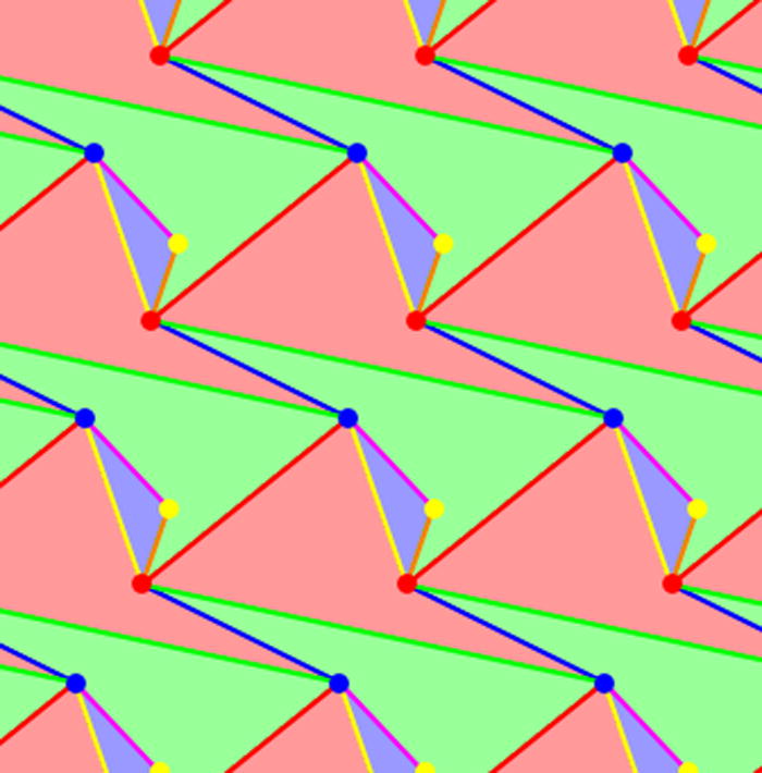
A planar periodic pseudo-triangulation.
We have also shown that expansive implies auxetic, hence this leads to an infinite gallery of planar auxetic periodic mechanisms, by virtue of the fact that all periodic pseudo-triangulations have exactly one degree of freedom to deform. While periodic pseudo-triangulations are easy to generate (see [6] section 5(i) for a description and illustration of the procedure), proving their stated properties is not so elementary. Interested readers can find the full treatment in [5].
The expansive implies auxetic principle is valid in arbitrary dimension, but the structure of expansive periodic frameworks in three or higher dimensions is only partially understood [4]. In [6], we have relied on the suggestive value of necessary conditions for expansiveness for a couple of new designs of three dimensional periodic frameworks with auxetic capabilities.
Main contribution
In the present work, we formulate and prove, in arbitrary dimension d ≥ 2, a general principle for converting a finite linkage with adequate prerequisites on d pairs of unconnected joints into a periodic framework with auxetic capabilities. From the standpoint of geometric auxetics [6] these prerequisites are natural, elementary and easily satisfied. This implies endless possibilities for auxetic design in arbitrary dimension.
Overview
In order to control the number of degrees of freedom, we start with a finite linkage in ℝd without self-stress, that is, with infinitesimally independent edge constraints. If the linkage has d pairs of vertices which provide, as free vectors, a basis of ℝd, we adopt the lattice generated by these vectors as periodicity lattice and obtain an associated periodic framework by replicating the finite piece via all translations in the periodicity lattice. This basic construction converts the finite linkage into a periodic framework with the same number of (periodic) degrees of freedom, or, more precisely, with the same smooth local deformation space. Thus, in order to obtain auxetic capabilities for the periodic framework we have to require adequate deformations for the finite linkage. It will be seen, as we unfold this scenario, that the resulting requirement is simply an expression of the defining property of auxetic trajectories and can be satisfied by an infinite gallery of finite linkage designs. We emphasize the fact that both the simplicity of the principle and the unlimited variety of possible examples have their roots in our geometric theory of auxetic deformations [6].
After reviewing in Section 2 the essential ingredients of this geometric approach, we describe the passage from finite linkages to periodic frameworks in Section 3. The design requirement for obtaining periodic frameworks with auxetic capabilities is stated in Section 4 and then construction techniques for finite linkages with appropriate features are developed in Section 5. Procedures for reducing the number of degrees of freedom to one and obtaining auxetic periodic mechanisms are described next. In Section 7 we show that affine transformations of a periodic framework preserve the infinitesimal auxetic cone. This result is relevant for classification criteria. A gallery of examples in Section 8 presents an infinite series of auxetic periodic mechanisms in dimension three. We mention some topics worthy of further investigation in our concluding Section 9.
2 The geometric theory of periodic auxetics
In this section, we review the essential notions of our geometric theory of auxetic one-parameter deformations of periodic frameworks. For more background and full details, we refer to [2, 6].
Periodic graph
A d-periodic graph is a pair (G, Γ), where G = (V, E) is a simple infinite graph with vertices V, edges E and finite degree at every vertex, and Γ ⊂ Aut(G) is a free Abelian group of automorphisms which has rank d, acts without fixed points on vertices and edges and has a finite number of vertex and orbits. The group Γ is isomorphic to Zd and is called the periodicity group of the periodic graph G. Its elements γ ∈ Γ ≃ Zd are referred to as periods of G.
Periodic placement of a periodic graph
A periodic placement of a d-periodic graph (G, Γ) in ℝd is defined by two functions:
where p assigns points in ℝd to the vertices V of G and π is an injective homomorphism of Γ into the group T(ℝd) of translations in the Euclidean space ℝd, with π(Γ) being a lattice of rank d. These two functions must satisfy the natural compatibility condition: p(γv) = π(γ)(p(v)).
Periodic framework
A placement which does not allow the end-points of any edge to have the same image defines a d-periodic bar-and-joint framework in ℝd, with edges (u, v) ∈ E corresponding to bars (segments of fixed length) [p(u), p(v)] and vertices corresponding to (spherical) joints. Two frameworks are considered equivalent when one is obtained from the other by a Euclidean isometry.
Periodic deformation
A one-parameter deformation of the periodic framework (G, Γ, p, π) is a (smooth) family of placements pτ : V → ℝd parametrized by time τ ∈ (−ε, ε) in a small neighborhood of the initial placement p0 = p, which satisfies two conditions: (a) it maintains the lengths of all the edges e ∈ E, and (b) it maintains periodicity under Γ, via faithful representations πτ : Γ → T(ℝd) which may change with τ and give an associated variation of the periodicity lattice of translations πτ(Γ).
After choosing an independent set of generators for the periodicity lattice Γ, the image πτ(Γ) is completely described via the d × d matrix Λτ with column vectors given by the images of the generators under πτ. The associated Gram matrix is given by:
Auxetic path
A deformation path (G, Γ, pτ, πτ), τ ∈ (−ε, ε) is called auxetic when the curve of Gram matrices ω(τ) defined above has all its tangents in the cone of positive semidefinite symmetric d × d matrices. When all tangents are in the positive definite cone, the deformation is called strictly auxetic.
This form of the auxeticity criterion, established in [6], Thm. 3.1, will be convenient for our present purposes. We note that the auxetic character of a one-parameter deformation is determined by the curve of Gram matrices of a basis of periods and strict auxeticity at one instance implies strict auxeticity in a neighborhood.
3 From finite to periodic
We assume a given dimension d ≥ 2. A linkage in ℝd is a pair L = (G, p), where G = (V, E) is a simple connected graph with n = |V| vertices and m = |E| edges and p : V → ℝd is a placement of the vertices in ℝd. Edges are then conceived as rigid straight bars between the corresponding vertices, which serve as spherical joints for the linkage. It is assumed here that all edges correspond to non-zero segments. Linkages which differ by an isometry of ℝd are considered equivalent, that is T ○ p and p are equivalent placements for any Euclidean isometry T. Simply put, equivalent linkages are identified.
The kinematics of linkages is a classical topic and we mention here only aspects and results directly relevant for our constructions. In particular, we use only linkages with infinitesimally independent edge constraints. In other words, the rows of the rigidity matrix are linearly independent. By the implicit function theorem, the local deformation space will be smooth, of dimension
| (1) |
where is the dimension of the Euclidean isometry group E(d). We will need f ≥ 1, when f is also called the number of degrees of freedom of the linkage.
For the construction we are about to describe, we assume that d pairs of vertices {vi(k), vj(k)} ⊂ V, k = 1, …, d, have been given, with the property that the vectors
| (2) |
form a basis of ℝd. Note that, while in each pair vi ≠ vj, different pairs may share one vertex.
Let , be the rank d lattice generated by this basis. This lattice will play the role of periodicity lattice for the periodic framework associated to our linkage with marked pairs.
We observe first that when we identify in G all vertices which appear in one of the given pairs, that is, if we put vi(k) ≡ vj(k), k = 1, …, d and maintain all edges (some possibly converted into loops), we obtain a quotient multigraph with exactly ñ = n − d vertices and edges.
Let be a complete set of representatives for the n − d vertices of the quotient multigraph. Then, the vertices of the periodic graph will be recorded as symbols v + λ, , λ ∈ Λ and placed by at . The edge set of the periodic graph is made of all (formal) Λ translates of E (with V seen as included in ). For periodicity group Γ we have Λ itself, with the natural action on . The resulting periodic framework , where π is the identification Γ = Λ, does not depend on the choice of representatives .
Figure 2 illustrates the procedure for d = 2. The planar linkage is a four-bar mechanism configured as a pseudo-triangle. The chosen pairs of vertices correspond to the diagonals. The associated periodic framework is a periodic pseudo-triangulation described as a “double arrowhead” pattern.
Figure 2.
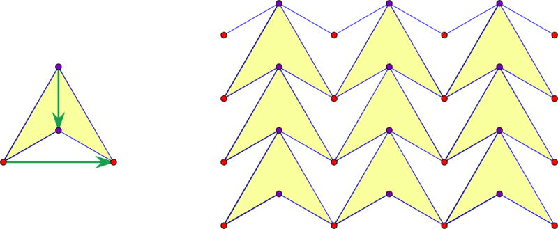
A planar four-bar mechanism with two marked pairs of vertices and the associated “double arrowhead” periodic framework.
We summarize the general procedure as follows.
Theorem 1
Let L = (G, p) be a connected linkage in ℝd, with n vertices and edges, such that:
the m edges impose infinitesimally independent constraints,
there are d marked pairs of vertices, with the corresponding vectors (2) providing a basis of ℝd.
Then, there is a unique periodic framework , with the following four properties:
the periodicity group Γ is identified with the lattice generated by the given basis,
the linkage L is contained in the framework ,
the edges of L provide a complete set of representatives for the edge orbits of under periodicity,
every vertex orbit of has at least one representative in L and the quotient is the finite multigraph described above.
This unique associated periodic framework has ñ = n − d vertex orbits and edge orbits and the local deformation spaces of L and can be identified. Their common dimension is
| (3) |
The claim on preservation of degrees of freedom follows immediately from [2], p.2641. In particular, the last term in (3) is the dimension formula for periodic deformations when edge constraints are infinitesimally (and hence locally) independent.
The reader may observe that the planar framework in Figure 1 can also be obtained (in two ways) by a passage from finite to periodic.
4 The main auxetic design principle
The correspondence described in Theorem 1 turns a finite linkage L = (G, p) into a periodic framework with the same local deformation space. Thus, a one-parameter local deformation (G, pτ) for L turns into a (periodic) one-parameter local deformation for . If we want the latter to be an auxetic path, the criterion of [6], Thm. 3.1, recalled above at the end of Section 2, requires the generators of the periodicity lattice to give a curve of Gram matrices ω(τ) with tangent directions in the positive semidefinite cone. Obviously, this curve is determined by the effect of the linkage deformation pτ on the d pairs of vertices marked on the linkage at the outset.
The essence of our auxetic design principle can be stated already.
Theorem 2
The periodic framework has a non-trivial auxetic deformation path if and only if the finite linkage L has a local one-parameter deformation with the following property: the Gram matrix of the basis given by the d marked pairs of vertices evolves (in the space of d × d symmetric matrices) as a non-constant curve with all its tangents in the positive semidefinite cone.
An important case, which involves only infinitesimal considerations, is when the tangent direction at the initial moment τ = 0 is actually in the positive definite cone. By continuity, this is enough to guarantee an interval τ ∈ (− ε, ε) where the tangent remains in the positive definite cone and the periodic deformation is strictly auxetic.
For explicitness, we unfold the more formal details. With notations introduced above in (2), the variation with τ of the marked basis is given by
| (4) |
The d × d matrix with these column vectors is denoted Λ(τ), hence the Gram matrix of the marked basis is
| (5) |
The velocity vector at moment τ for this parametrized curve is
| (6) |
The auxeticity requirement is that all velocity vectors (6) for τ in a small neighborhood of 0 belong to the positive semidefinite cone. At moment τ = 0, we have Λ(0) = Λ and
| (7) |
with the derivative depending only on the infinitesimal deformation corresponding to pτ. As noticed above, when (7) is in the interior of the positive semidefinite cone, that is is positive definite, strict auxeticity follows for small enough τ. We state explicitly this corollary, since this form of the principle implicates only infinitesimal deformations of L and is most useful for constructing examples.
Corollary 3
If, for some infinitesimal deformation of L, the corresponding infinitesimal variation of the Gram matrix is positive definite, the periodic framework has a strictly auxetic deformation path.
For a simple illustration, we revisit the example given in Figure 2. The quadrilateral has one degree of freedom and the obvious local deformation for our symmetric configuration, shown in Figure 3, increases the lengths of the two diagonals, while maintaining their orthogonality. This means that is a diagonal 2 × 2 matrix with positive diagonal entries. Hence, the double arrowhead periodic framework is a strictly auxetic one degree of freedom periodic mechanism (as long as the quadrilateral remains concave i.e. remains a pseudo-triangle).
Figure 3.

Deforming the quadrilateral in Figure 2.
5 Construction techniques
In this section we discuss construction techniques for obtaining finite linkages L which satisfy the auxetic requirement formulated in Theorem 2, or rather the strict auxetic criterion of Corollary 3. It will soon become apparent that examples can be constructed ad libitum in any dimension d ≥ 2. The general construction ideas surveyed here offer wide opportunities for applications, since additional specifications can be met by ingenuity and refinement in the finite linkage design.
We begin with an examination of the case when all d pairs of vertices marked on the linkage L = (G, p) have a common vertex v0. Convenient labeling will have our basis expressed as
| (8) |
with the Gram matrix ω = (〈λi, λj〉)ij, 1 ≤ i, j ≤ d. Thus, we aim at designing L, so that it has an infinitesimal deformation making the corresponding infinitesimal variation of the Gram matrix positive definite.
We may assume, without violating the condition on infinitesimally independent edge constraints, that L contains a rigid part (e.g. a d-dimensional simplex) and we shall refer to it as the “scaffold”. Then, we can attach to this scaffold, without any redundancy of new bars, other elements of the linkage, with adequate control on the possible motion of certain “vertices of interest”. In our case, the vertices of interest are those labeled v0, …, vd, and we may connect them to the scaffolding as follows: v0 is rigidly connected, while each vk, k = 1, …, d is attached via a “hinge connection”, to be described in the next lemma, which allows only one degree of freedom relative to the scaffold, namely the rotation of vk around that hinge.
Lemma 4
Suppose we have a (spanning and minimally) rigid linkage in ℝd, referred to as a “scaffold”. Suppose we have a new vertex v and we want to connect it to the scaffold in such a way that it has only one degree of freedom with prescribed direction for its infinitesimal motion relative to the scaffold. Then, we choose a (d − 2)-simplex, referred to as a “hinge” and position it in the hyperplane through v with normal direction prescribed by the infinitesimal motion allowed for v (but away from v). We connect this hinge rigidly (and without redundancy) to the scaffold and connect v to the (d − 1) vertices of the simplex. The resulting linkage allows only a rotation of v around the hinge as relative motion and the infinitesimal direction of motion is the one prescribed.
Remark
In more suggestive terms, this lemma may be called “the trapdoor principle”, since v and the hinge form a panel (codimension one “trapdoor”) and this panel can only rotate around its fixed hinge. In Figure 4 we show the result of applying this principle to obtain a linkage in R3 with controlled motion for three vertices relative to a (fixed) tetrahedral scaffold. The three marked arrows would be λk, k = 1, 2, 3 and this shows that their infinitesimal variation can be arranged to yield a positive definite , as argued in the next lemma.
Figure 4.
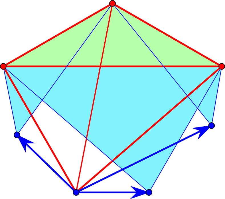
Paneled simplex
Lemma 5
Suppose p0, p1, …, pd are points in ℝd with
a basis of ℝd. The point p0 is assumed fixed and may be taken as the origin. The points pk are subject to infinitesimal displacements μk ≠ 0 which have the direction of the corresponding altitude from pk in the simplex [p0…pd] and are all pointing outwards. Then, the resulting infinitesimal variation of the Gram matrix ω = (〈λi, λj〉)ij is positive definite.
Proof
Let us assume that only one point, say pk, moves infinitesimally by μk ≠ 0, with the other points fixed. Then is positive semidefinite of rank one, with the only non-zero entry at (k, k). The lemma follows by linear combination (with all coefficients one).
In summary, the trapdoor principle (Lemma 4) shows how to design a linkage with prescribed infinitesimal motions for marked vertices v0, …vd. When these prescriptions are as in Lemma 5 (with pi = p(vi)) we obtain a positive definite infinitesimal variation of the Gram matrix of periods, hence strictly auxetic capabilities for the associated periodic framework. Figure 5 illustrates this type of construction for d = 2.
Figure 5.
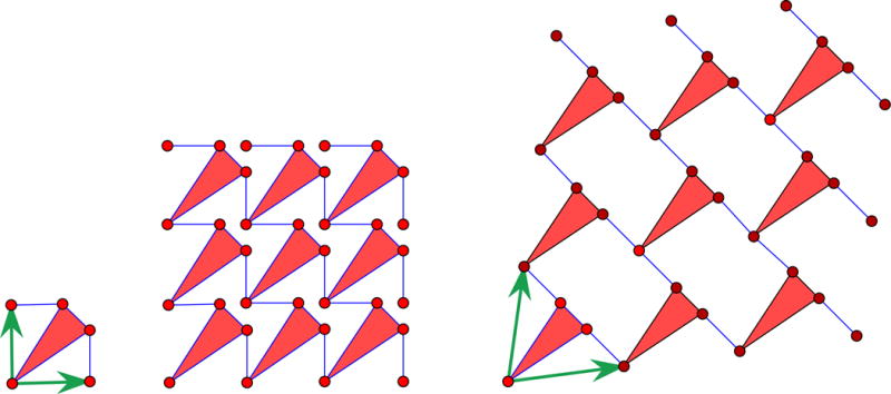
A finite linkage with two degrees of freedom with auxetic capabilities for the associated periodic framework. The deployed configuration on the right can be reached via an auxetic path.
Figure 6 shows the three-dimensional version of the same scheme.
Figure 6.
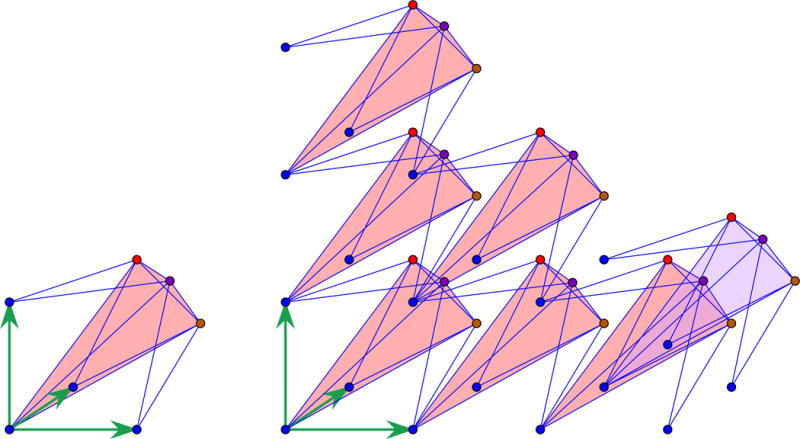
The d = 3 version of the planar scenario in Figure 5. The finite linkage is a paneled tetrahedron, as in Figure 4. Only one ‘in depth’ translate is shown.
Note that these constructions lead to linkages with d degrees of freedom. In Section 6 we describe a simple reduction procedure to one degree of freedom and strictly auxetic motion for the associated periodic framework.
It is fairly transparent by now that similar scenarios apply for other patterns of d pairs of vertices in the finite linkage L. If we consider, for instance, the case of no common vertex for any two pairs, we may label the pairs (vk, wk), with basis
We may design L with all vk, k = 1, …, d fixed to the scaffold and λk mutually orthogonal and each wk constrained by hinge connections to move infinitesimally along λk. Again, we obtain associated periodic frameworks with strictly auxetic capabilities.
For other patterns of d marked pairs one may use orthogonal splittings of ℝd and maintain orthogonality for adequate partitions of the d pairs. We dispense with further inventory pursuits here and consider instead a type of structure which will be useful for deriving an explicit infinite series of non-isomorphic d-periodic graphs underlying auxetic periodic mechanisms for d ≥ 3.
Let d ≥ 3 and consider the finite linkage in ℝd with n = d + 2 vertices and m = 2d edges which corresponds to the case shown in Figure 7 for d = 3. For a more suggestive description, we adopt the following language. There is a hyperplane, to be called ‘floor’, which contains d of the placed vertices, configured as a regular (d − 1)-simplex, but not connected by edges. The two remaining vertices lie above the center of the (d − 1)-simplex and both are connected by edges to all d points on the floor. As a result, all bars from one or the other of the two points are of equal length and the line through the two points is orthogonal to the floor (and will be called ‘vertical’). The vectors given by d marked pairs of vertices are: the vertical vector between the two points above the floor and the (d − 1) ‘horizontal’ vectors from one point on the floor to the remaining (d − 1) points on the floor.
Figure 7.
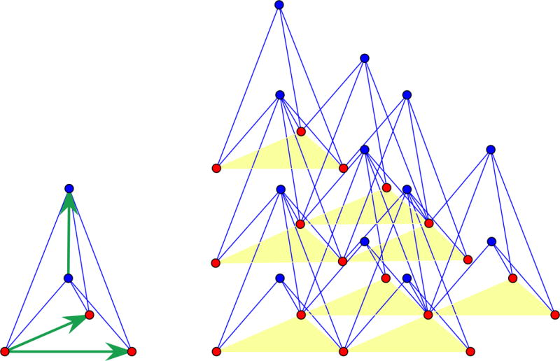
A finite linkage in R3, with 5 vertices, 6 edges and 3 pairs of vertices marked by arrows. A fragment of the associated periodic framework is shown nearby. It has 2 orbits of vertices and 6 orbits of edges modulo periodicity.
The indicated vectors become periods and generate the periodicity lattice for the associated periodic framework. We see that, when using horizontal periods, the floor hyperplane goes to itself and gives a floor for the periodic framework. Repeated translations by the vertical period will generate an infinite array of such floors. Floors do not contain edges. In Figure 7, replicas of the floor (d − 1)-simplex are highlighted.
There are degrees of freedom and a natural set of parameters for the deformations of the finite linkage would be the (squared) distances between the vertices of the floor simplex. A strictly auxetic deformation trajectory for the periodic framework can be immediately proposed based on a dilation motion for the floor simplex. The vertical vector remains orthogonal to the floor since the two end-points project to the circumcenter of the floor simplex. The end-point closer to the floor approaches faster than the remote one, resulting in a (squared) length increase for the vertical period vector. Thus, is clearly positive definite for this kind of local deformation trajectory. Other auxetic trajectories (with semipositive definite of rank two) will be described in the next section, in connection with ways of reducing from degrees of freedom to one.
6 Reduction to one degree of freedom
In this section we show first that the periodic frameworks with d degrees of freedom obtained when using our auxetic design principle in the manner described in Section 5 can be turned into periodic frameworks with a single degree of freedom which are locally strictly auxetic.
More precisely, let us assume that we have constructed a finite linkage L = (G, p) in ℝd, with d pairs of vertices marked as (v0, vk), k = 1, …, d. We assume at the same time, that the rigid part of L called scaffold is fixed and includes v0, which is placed at the origin. The linkage has d degrees of freedom due to the hinge connections of the d vertices vk, k = 1, …, d, to the scaffold.
We let pk = p(vk), k = 1, …, d denote the initial positions and consider a deformation path with infinitesimal displacements for the vertices vk, as needed when satisfying a strictly auxetic prerequisite. In particular, this is the setting illustrated above in connection with Figures 5 and 6.
Lemma 6
The linkage L can be turned into a linkage L* which has a single degree of freedom and a deformation path with the same infinitesimal displacements for the vertices vk, k = 1, …, d.
Proof
We introduce a new vertex w with a sufficiently general position q. We connect w with all vk, k = 1, …, d. Then, the infinitesimal displacement of w which is compatible with the infinitesimal displacements is uniquely determined by the linear system:
| (9) |
Now, we may apply the ‘trapdoor principle’ (Lemma 4) and construct a hinge connection for w to the scaffold, with as the allowed direction of infinitesimal displacement. Thus, a total of (2d − 1) edges emanate from w. This yields the desired linkage L* with one degree of freedom.
We illustrate in Figure 8 a simple conversion of the linkage used earlier in Figure 5 into a linkage with just one degree of freedom. Obviously, this kind of operation has considerable leeway.
Figure 8.
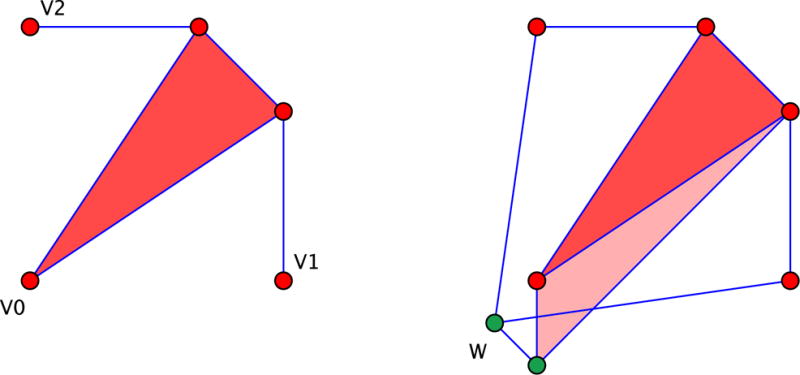
The planar linkage in Figure 5 has two degrees of freedom but can be converted to a single degree of freedom mechanism which retains the desired infinitesimal deformation on the vertices v0, v1, v2.
Remark
For the associated periodic framework we obtain strict auxeticity (i.e. positive definite) at the initial moment, hence a strictly auxetic deformation path defined on some interval (− ε, ε).
A somewhat different procedure will be described presently for the type of frameworks related to Figure 7. In this setting, d ≥ 3 and the task is to reduce the degrees of freedom from down to one. For simplicity and the benefit of figures, we conduct our discussion in dimension three. The arguments in higher dimensions are completely analogous.
The main idea is illustrated in Figure 9. We operate in the associated periodic framework, where we want to introduce new edge orbits, that is (for d = 3) two new edge orbits. Recall that highlighted triangles belong to stacked floors. Floors do not contain edges, but are organized by horizontal periodicity. The figure shows three triangles in one floor and one triangle in the floor above. The representatives TN and TC of the two new edge orbits are shown as darker segments.
Figure 9.
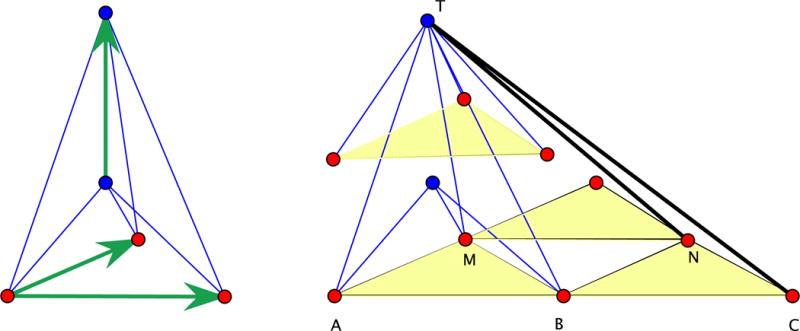
Two new edge orbits in the associated periodic framework.
Note that the three edges from the top vertex to the triangle in the upper floor belong, by periodicity, to the original periodic framework, which has six edges incident to every vertex. Recall that we assumed an initial configuration with equilateral floor triangles and the vertical periods positioned over the centers of floor triangles. With the two new edge orbits, we obtain a periodic framework with the same periodicity lattice, but with eight edges incident to every vertex. In the figure, only the top vertex shows all eight bars incident to it. With these caveats taken into account, we proceed with the arguments which prove the auxetic character of the resulting periodic mechanism.
The triangle TAC is determined by the two edges TA and TC, together with the median TB. This means that the horizontal period AB has determined length. Since MN is the same period, the triangle TMN is completely determined. Thus, the periodic mechanism can only open up the dihedral angle of the planes TAB and TMN which have a common line with the direction of the period AB. Since T remains on the perpendicular bisector of AB, so does M. Thus, N remains on the perpendicular bisector of BC. We have argued earlier that the vertical period remains vertical (i.e. perpendicular on the floor) and increases in length. All in all, the infinitesimal variation of the Gram matrix of periods has two positive diagonal entries (corresponding to the vertical period and AM) and zero elsewhere. Hence the motion is auxetic.
Remark
For a suggestive reading of Figure 9 in higher dimension d, the AB part of the floor triangle should be conceived as a facet of the floor simplex. The vertex T will be connected to all but one of the vertices and edge-midpoints of the duplicated simplex in the lower floor. All edges incident to T in the resulting one degree of freedom periodic framework are contained in two hyperplanes (‘roofs’), which play the role of the two planes TAC and TMN in the figure. The auxetic mechanism may be fancied as a periodic array of (crisscrossing and interlaced) opening roofs as proposed in Figure 10.
Figure 10.
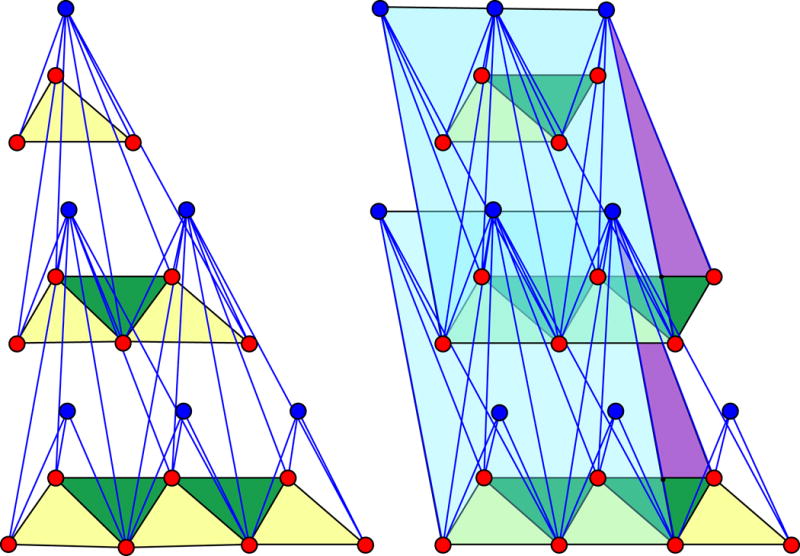
Auxetic mechanism. The fragment shows three floors. Alternative view as “breathing stacked roofs”. Inhaling is auxetic. The one degree of freedom deformation can be parametrized by the dihedral angle of a roof. The floors vary accordingly. The framework edges are all contained in roof planes. Floors contain no edges but must respect periodicity constraints.
We may observe at this point that there are other ways of introducing new edge orbits for a reduction to one degree of freedom mechanisms. If we follow the pattern indicated in Figure 11, we obtain a series of non-isomorphic periodic graphs with framework realizations which are auxetic periodic mechanisms. Since the roof planes are the same in this series, the resulting auxetic mechanisms are kinematically equivalent, although structurally distinct. This shows that equivalence criteria in periodic auxetics must be introduced with some care. Another aspect deserving attention when attempting classifications is affine equivalence, discussed in the next section.
Figure 11.

Alternative way for introducing new edge orbits (in the same roof planes).
7 Affine transformations
In this section we show that the infinitesimal auxetic cone of a periodic framework is preserved under affine transformations, that is, the natural isomorphism of the corresponding vector spaces of infinitesimal deformations [2], Prop. 3.7, pg. 2639, takes one auxetic cone to the other. While this fact is not directly intuitive, it has a straightforward and short proof in our geometric theory of periodic auxetics.
We adopt the following notations and setting: is a periodic framework in ℝd, with n vertex orbits and m edge orbits. After a choice of independent generators for Γ, the lattice of periods π(Γ) of the framework is described by a d×d matrix Λ, with columns given by the images of the generators. We denote by pi, i = 1, …, n the positions of a complete set of representatives for the vertex orbits. An infinitesimal deformation of the framework is determined by the infinitesimal variation of the positions pi and the infinitesimal variation of the periodicity matrix Λ.
Since the effect of translations is trivial, we assume our affine transformation to be a linear map A : ℝd → ℝd. Then the transformed framework has vertex representatives at Api and periodicity matrix Λ1 = AΛ. The natural isomorphism between infinitesimal deformations takes for to for . Thus, and
Auxetic deformations for are those with positive semidefinite and the isomorphism gives
| (10) |
confirming the preservation of the auxetic cone.
Remark
When interpreted in the context of our auxetic design principles, this result says that if a finite linkage L in ℝd satisfies the strict auxetic prerequisites for d pairs of vertices, then any affine transform of L will satisfy those prerequisites for the corresponding d pairs. Nevertheless, the intervals where an auxetic path for the associated periodic frameworks would be defined may well differ.
8 An infinite gallery
Our gallery is dedicated to new examples in dimension three. We show that our main auxetic design principle can be applied to an infinite series of finite linkages in R3 of a rather elementary nature. We use minimally rigid linkages with one edge removed and adequate marking of three pairs of vertices.
Let k ≥ 3 be an integer and consider a regular polygon with 3k edges inscribed in the unit circle. The plane of the circle will be called horizontal. We mark as v0, v1, v2 three vertices which have from one to another exactly k edges and form an equilateral triangle. Then, we take two points w1, w2 on the vertical axis through the center of the circle. We assume w1 closer to the horizontal plane. The linkage denoted Mk has n = 3k +2 vertices and m = 9k edges and is obtained from the regular polygon by connecting w1 and w2 to all its vertices. When w1 and w2 are on opposite sides of the horizontal plane, we have the one-skeleton of a convex polyhedron with triangular faces. By Cauchy’s theorem, the linkage is minimally rigid. When we reflect the vertex w1 and its adjacent edges in the horizontal plane, minimal rigidity will hold as well, since all vertices on the horizontal circle must remain on the circle of intersection of two spheres (centered at w1 and w2). We’ll need the case with w1 and w2 on the same side, say above the horizontal plane. The linkage to be used for obtaining a periodic framework is denoted Lk and is derived from Mk by deleting an edge from the polygonal chain between v1 and v2 and marking the three pairs of vertices (w1, w2), (v0, v1) and (v0, v2). Figure 12 shows L3 next to the planar diagram used for describing its motion.
Figure 12.
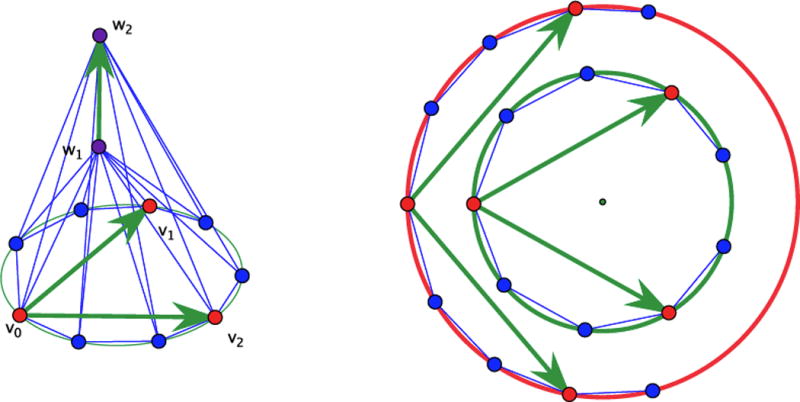
The finite linkage L3 with a diagram for the deformation effect in the horizontal plane.
The deformation mechanism of Lk is easily represented since the vertices of the horizontal polygon must remain on a circle. When following the deformation trajectory in the direction of an augmenting radius for this circle, the vector from w1 to w2 remains orthogonal to the circle plane and locally increases in length. Thus, for strict auxeticity, we have to examine only the variation of the 2 × 2 Gram matrix of the two vectors, say λ1, λ2, corresponding to the pairs (v0, v1) and (v0, v2). This is an elementary computation. With the radius r of the circle as parameter, we find:
| (11) |
where the expression of θ as a function of r is given by
| (12) |
For the Gram matrix ω(r) = (〈λi, λj〉), 1 ≤ i, j ≤ 2, it follows that is positive definite. We conclude (via Corollary 3) that the one degree of freedom periodic framework associated to Lk is a strictly auxetic periodic mechanism in a neighborhood of the initial position. Thus, with k ≥ 3, we obtain an infinite series of distinct auxetic periodic structures.
Remark
Considering that a small enough change in the placement of the vertices will maintain strict auxeticity, the self-crossing resulting in the periodic framework from the planarity of the polygonal vertices in Lk can be avoided by starting with a slightly distorted version of Lk.
9 Conclusion
The mathematical design principles presented here are based on the geometric foundations of periodic auxetics introduced in [6]. We have shown that, in spite of a rather sparse collection of auxetic designs in the existing literature, there are unlimited possibilities for generating periodic frameworks with auxetic capabilities in any dimension. The main procedure discussed in this paper converts any finite bar-and-joint mechanism in ℝd with adequate motion for d marked pairs of joints into an auxetic periodic framework mechanism.
This work has brought to higher visibility a number of topics and features which deserve further investigation. We propose them as open problems.
Identify the class of periodic graphs obtained by the passage from finite to periodic described in Section 3.
Formulate precise and useful criteria for equivalence/non-equivalence of auxetic periodic mechanisms.
Determine and control the interval where a deformation path remains auxetic.
Acknowledgments
The first author acknowledges partial support through NSF award no. 1319389 and the second author acknowledges partial support through NSF award no. 1319366. Both authors are partially supported through NIH Grant 1R01GM109456. All statements, findings or conclusions contained in this paper are those of the authors and do not necessarily reflect the position or policy of the US Government. No official endorsement should be inferred.
References
- 1.Bertoldi K, Reis PM, Willshaw S, Mullin T. Negative Poisson’s ratio behavior induced by an elastic instability. Adv Mater. 2010;22:361–366. doi: 10.1002/adma.200901956. [DOI] [PubMed] [Google Scholar]
- 2.Borcea CS, Streinu I. Periodic frameworks and flexibility. Proceedings of the Royal Society A. 2010 Sep;466(2121):2633–2649. doi: 10.1098/rspa.2009.0676. [DOI] [Google Scholar]
- 3.Borcea CS, Streinu I. Kinematics of expansive planar periodic mechanisms. In: Lenarcic J, Khatib O, editors. Advances in Robot Kinematics. Springer Verlag; 2014. pp. 395–408. [Google Scholar]
- 4.Borcea CS, Streinu I. Expansive periodic mechanisms. IMA Conference on Mathematics of Robotics. 2015 Sep; arXiv:1507.03132. [Google Scholar]
- 5.Borcea CS, Streinu I. Liftings and stresses for planar periodic frameworks. Discrete and Computational Geometry. 2015 Jun;53(4):747–782. doi: 10.1007/s00454-015-9689-7. [DOI] [PMC free article] [PubMed] [Google Scholar]
- 6.Borcea CS, Streinu I. Geometric auxetics. Proceedings of the Royal Society A. 2015 doi: 10.1098/rspa.2015.0033. [DOI] [Google Scholar]
- 7.Cabras L, Brun M. Auxetic two-dimensional lattices with Poisson’s ratio arbitrarily close to -1. Proceedings of the Royal Society A. 2014;470(20140538) doi: 10.1098/rspa.2014.0538. [DOI] [Google Scholar]
- 8.Elipe JCA, Lantada AD. Comparative study of auxetic geometries by means of computer-aided design and engineering. Smart Materials and Structures. 2012;21:105004. [Google Scholar]
- 9.Evans KE, Nkansah MA, Hutchinson IJ, Rogers SC. Molecular network design. Nature. 1991;353:124–125. [Google Scholar]
- 10.Greaves GN. Poisson’s ratio over two centuries: challenging hypotheses. Notes and records of the Royal Society of London. 2013;67:37–58. doi: 10.1098/rsnr.2012.0021. [DOI] [PMC free article] [PubMed] [Google Scholar]
- 11.Greaves GN, Greer AI, Lakes R, Rouxel T. Poisson’s ratio and modern materials. Nature Materials. 2011;10:823–837. doi: 10.1038/nmat3134. [DOI] [PubMed] [Google Scholar]
- 12.Grima J, Alderson A, Evans KE. Auxetic behavior from rotating rigid units. Physica status solidi B. 2005;242:561–575. [Google Scholar]
- 13.Lakes R. Foam structures with a negative Poisson’s ratio. Science. 1987;235:1038–1040. doi: 10.1126/science.235.4792.1038. [DOI] [PubMed] [Google Scholar]
- 14.Lee JH, Singer JP, Thomas EL. Micro-/nanostructured mechanical metamaterials. Advanced Materials. 2012;24:4782–4810. doi: 10.1002/adma.201201644. [DOI] [PubMed] [Google Scholar]
- 15.Milton GW. Composite materials with Poisson’s ratios close to -1. Journal Mech Phys Solids. 1992;40:1105–1137. [Google Scholar]
- 16.Mitschke H, Robins V, Mecke K, Schroeder-Turk GE. Finite aux-etic deformations of plane tessellations. Proceedings of the Royal Society A. 2013;469(20120465) [Google Scholar]
- 17.Mitschke H, Schury F, Mecke K, Wein F, Stingl M, Schröder-Turk GE. Geometry: The leading parameter for the Poisson’s ratio of bending-dominated cellular solids. Int J Solids Struct. 2016;100–101:1–10. [Google Scholar]
- 18.Reis PM, Jaeger HM, van Hecke M. Designer matter: A perspective. Extreme Mechanics Letters. 2015;5:25–29. [Google Scholar]
- 19.Tanaka H. Bi-stiffness property of motion structures transformed into square cells. Proceedings of the Royal Society A. 2013;469(20130063) doi: 10.1098/rspa.2013.0063. [DOI] [Google Scholar]
- 20.Wang F, Sigmund O, Jensen JS. Design of materials with prescribed nonlinear properties. Journal Mech Phys Solids. 2014;69:156–174. [Google Scholar]


