Significance
Plasmas at atmospheric pressure conditions are ubiquitous, in natural form, such as the familiar lightning, or produced through artificially created electromagnetic or electrostatic fields for industrial and scientific applications. One distinctive feature of these cold-type plasmas is their lack of a topologically defined shape, concurrent with spatial unsteadiness and nonuniformity. Here, we report the observation of a coherent and stable toroidal plasma that spontaneously forms under extreme hydrodynamic shear, without external electromagnetic action. The confined and chamberless nature of this plasmoid has potential implications for the investigation of plasma–matter interactions, in the development of plasma-based deposition techniques for the microelectronics industry, in the emerging field of plasma medicine, or as a model for energy-storing self-maintained plasmoids.
Keywords: water jet, hydrodynamic shear, tribo-electricity, luminescence, toroidal plasmoid
Abstract
Saint Elmo’s fire and lightning are two known forms of naturally occurring atmospheric pressure plasmas. As a technology, nonthermal plasmas are induced from artificially created electromagnetic or electrostatic fields. Here we report the observation of arguably a unique case of a naturally formed such plasma, created in air at room temperature without external electromagnetic action, by impinging a high-speed microjet of deionized water on a dielectric solid surface. We demonstrate that tribo-electrification from extreme and focused hydrodynamic shear is the driving mechanism for the generation of energetic free electrons. Air ionization results in a plasma that, unlike the general family, is topologically well defined in the form of a coherent toroidal structure. Possibly confined through its self-induced electromagnetic field, this plasmoid is shown to emit strong luminescence and discrete-frequency radio waves. Our experimental study suggests the discovery of a unique platform to support experimentation in low-temperature plasma science.
In the epic poem The Lusiads (1), the great Portuguese explorer Vasco da Gama narrates how, during his discovery voyage to the Indies, he “saw, and clearly saw, the living light” at the tip of his caravel’s masts. The recount describes from experimental evidence what is known as Saint Elmo’s fire to seafarers facing stormy weather. This luminous phenomenon is, with the more common lightning (2), perhaps the only other atmospheric pressure plasma found in nature.
Atmospheric pressure plasmas are a nonthermal nonequilibrium form of plasma that, as a technology, requires no chamber or complex vacuum machinery and has a considerable scientific and industrial potential. Applications in science and engineering span from analytical chemistry, material processing, environmental science, energy, medicine, biology, and low-temperature plasma physics to microelectronics and display technology (3–6). Unlike the natural counterparts, these plasmas are obtained by artificially created electromagnetic fields and tend to be nonuniform and unstable (7) without any defining morphology. In this context, miniaturizing and confining plasmas to microscales and in microcavities is considered a viable and promising approach (4, 5, 7, 8).
In air a high potential electric field applied between two electrodes can cause the ionization of the gas elements. The phenomenon manifests as a blue–pink luminescent cloud and is commonly known as an electrical corona. The physics and conditions for onset of this atmospheric pressure plasma are well understood (9). According to Paschen law, electric fields of are sufficient to trigger a corona in dry air.
Here we report on the observation of a naturally formed, stable, unconstrained but topologically confined microscale toroidal plasma in air, at room temperature and atmospheric pressure. We demonstrate the creation of an atmospheric pressure microplasma without external electromagnetic action, through focused hydrodynamic shear. By spectroscopic, electrical, physico-chemical, and radio-frequency experimental evidence, we postulate a scenario for its formation. Our study suggests that energetic free electrons are produced by tribocharging from intense hydrodynamic shear in a wall-impinging water jet. Electron collisions with water molecules trigger the formation of charge carriers, allowing the free electrons to reach the water–gas interface and pass into the gas phase, where a plasma forms through the excitation and ionization of the gas elements. When the surrounding gas is air, the plasma cloud shapes into a topologically coherent structure characterized by a radio-frequency signature compatible with plasma resonance frequencies.
Results
Discovery.
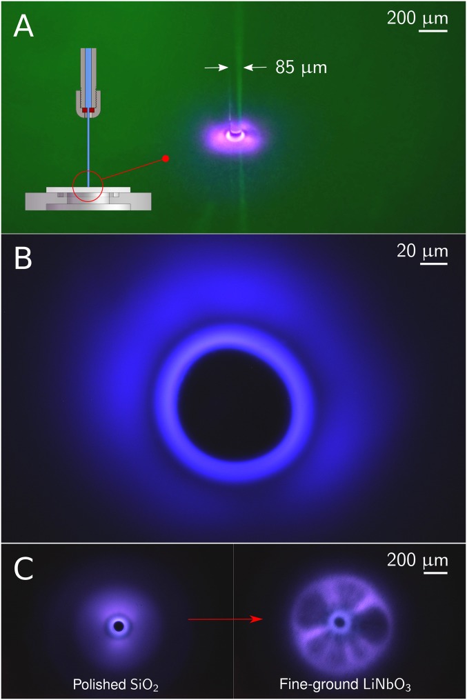
Self-generation of a toroidal microplasma was observed in the flow field of a water microjet in air impinging upon a dielectric surface. The experimental setup consisted of a ruby nozzle with a orifice diameter and a nonelectric pump, using deionized and bubble-free water. Single crystal quartz (SiO2) and single crystal lithium niobate (Z-cut LiNbO3) wafers were used as the target surface, polished or fine ground. A close-up view of the impinging jet is shown in Fig. 1A. Further details are given in SI Materials and Methods.
Fig. 1.
Close-up views in the flow field of the impinging jet in air. (A) Photograph of the laminar jet in open air impinging on a polished quartz surface; the jet diameter is . The transition of the impinging round jet to an expanding radial jet can be seen through the sharp jet annulus. Inset schematic shows the jet in the context of the experimental setup with the nozzle and the wafer support plate. (B) Optical access beneath the experimental setup was used to examine the visual and spectral content of the radiating light through high-resolution microscopy. This photograph, taken with a photographic sensitivity of 640 (ISO standard) and a 1/5-s exposure time, shows the luminescent structure as observed through the wafer surface with a 50× microscope objective. Water was impinging on a polished quartz surface with a velocity exceeding . The central dark disk corresponds to the radial cross-section of the jet. (C) Photographs of the luminescent structures taken with a 10× objective, on a polished quartz surface for a jet velocity of (Left) and on a fine-ground LiNbO3 surface for a jet velocity of (Right). Streamers, resembling those of common plasma balls, are seen in C, Right as they stretch radially from the impinging site. Note that color levels of images have been enhanced by for better display.
For jet velocities above and impingement on a polished quartz wafer, an intriguing bright luminescent blue–pink spot appeared over the core region of the jet. An apparently similar luminous effect has been reported either in passing (10) or under different contexts (11, 12), yet remained unexplained.
Upon optical magnification, a prominent and rich structure appeared as a well-defined luminescent toroid around the jet core, neighbored by a dark band and followed by a cloud-like glowing region (Fig. 1B and Fig. S1). The intensity of the luminescent ring was found to increase with jet velocity (Fig. S2). When the polished surface was replaced by a fine-ground one, a dramatic change occurred in the form of a brighter inner ring and the appearance of radial streamers (Fig. 1C and Fig. S3). Furthermore, the onset of luminescence was at a significantly lower velocity (). Despite the highly dynamic nature of these streamers, giving a visual perception of rotation and resembling the filamentary structures seen in common plasma balls (13), the central ring appeared to remain stable (Movie S1). Luminescence was not observed when ion-rich water or conducting surfaces were used.
Optical Emission Spectroscopy.
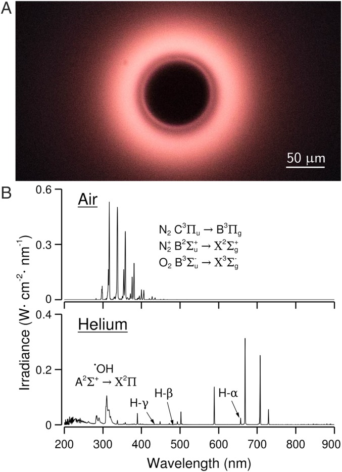
To pin down the location of the luminescence, we discharged the jet in an atmosphere of helium on the same polished quartz surface. A change in color confirmed that the light source resided in the gas phase (Fig. 2A and Fig. S4). Changing to a fine-ground LiNbO3 surface led to similar observations to those with SiO2 (Fig. S5). The confined nature of the toroidal plasma in air also changed to a diffused disk with no clear boundaries or well-defined rings.
Fig. 2.
Optical emission spectra. (A) The color of the rings changes noticeably when the gas is changed from air to helium. This photograph of the luminescent spot in helium atmosphere was taken through the impinging surface of a polished quartz wafer with a 10× microscope objective. Jet velocity was . (B) Luminescence spectra in air and helium on a polished quartz wafer. In air, we recognize the second positive system of N2. In helium, we notice the emission bands of the •OH radical in the region – (visible only on SiO2, for LiNbO3 optical transmittance starts at ) and the first three spectral lines of the Balmer series.
The light spectrum for air (Fig. 2B) shows the strong bands of the second positive system of molecular nitrogen (14) and weaker bands of the first negative system. N2 is excited and ionized from its ground state () to form (state ) and nitrogen ions (state ).The spontaneous transition to lower-energy states such as (N) and () results in UV emission. These spectral features were also observed with pure nitrogen and are typical of the phenomenon known as electrical corona (15). The emission bands of the transition of oxygen are also detected, although strongly shadowed by the N2 bands. The emission spectrum in helium gas (Fig. 2B) shows the bands characteristic of the transition of the OH-radical system () in the region –. We also note the presence of the (), (), and () lines of the Balmer series of hydrogen.
The presence of transition bands in air and the lack of ionization lines in helium suggest that energies at play can exceed but are below , respectively the ionization energies of molecular and atomic He. Finally, we verified that changing the target surface from SiO2 to LiNbO3, or from a polished to a fine-ground surface, did not affect the spectral emission pattern both in air and in helium atmospheres.
Plasma Characterization.
From the intensity ratio of the rotational lines (16), we infer a helium gas plasma temperature of –. The electron temperature and electron density in helium plasmas can be established (17) from the peak intensity ratios of the -nm, -nm, and spectral lines of , resulting in electron temperatures between eV and and electron densities between cm-3 and . A further estimate of the electron density is obtained from the Stark broadening (18) of the and lines of hydrogen and from specific lines of atomic He (19) ( nm, nm, nm, and ). Depending upon the fitting model (20), electron densities range from cm-3 to . The large difference between and confirms that the helium plasma is nonthermal.
In air, the largely dominant bands of the second positive system are used (21) to diagnose a plasma gas temperature in the range –. Assuming thermal equilibrium, an electron temperature of 2.64 eV is estimated (22) from the intensity ratio of the and the transitions, respectively at nm and . Thus, the air plasma is also a low-temperature, nonequilibrium plasma. However, estimation of the electron density from Stark broadening is not possible, for are needed to put hydrogen into its first excited state.
Finally, we also note that the line ratio between and or is strongly related (23) to the reduced field strength , with being the electric field strength and the density of neutral particles. We find a mean reduced field strength of 353 Td, with Td being the Townsend unit.
Electrostatic Field.
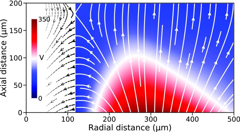
It is important to appreciate that we observed the toroidal plasma without any externally imposed electric field between well-defined nodes. However, our observation of excitation and ionization spectral lines in air suggests the presence of a strong electrostatic field in the neighborhood of the jet. In fact, a high negative potential with a large dynamic range ( V to ) was found between a probe placed inside the plasma and the ground (SI Materials and Methods), thus suggesting accrual of negatively charged particles therein. Fig. 3 shows the potential field in the close vicinity of the jet. The electric field (arrowed lines) indicates that negative charge carriers should emanate as free electrons from the neck region of the jet, suggesting that this annular area acts as a cathode. Similarly, an anode site is plausibly located in the radial distance range of –.
Fig. 3.
Potential and electric fields. We surveyed the region surrounding the toroidal plasma, using a probe at a fixed potential paired with a floating probe placed at various points in the plasma vicinity (SI Materials and Methods). The potential of the interior of the plasma was determined to be consistent enough to act as a reference potential. The color plot shows the isocontour map of the potential field , after interpolation of the experimental values. The electric field , represented here as white arrowed lines, was calculated by spatial derivation of the interpolated potential field . Within from the jet boundary where no data are available, the electric field is extrapolated to a radial distance of (dashed black arrowed lines).
The air plasma characterization can now be completed (see SI Detailed Calculations) in terms of electron density and plasma resistivity, the latter resulting from electron collisions with ions and neutral particles. Based on the estimated mean reduced field strength and the measured electric field strength (Fig. 3), we derive a mean neutral gas density . Based on the electron temperature obtained from the spectroscopic analysis, the electron–ion and electron–neutral collision frequencies are found to be and , respectively. Therefore, electron–ion Coulomb collisions dominate over electron–neutral collisions.
The resistivity induced by the electron–ion collisions, or Spitzer resistivity, is and contributes to the total plasma resistivity. The electron density is calculated to be and the degree of plasma ionization is , under the assumption of quasi-neutrality whereby the ion density is similar to . These findings are consistent with the observation that Coulomb collisions dominate; however, they are significantly higher than in typical corona discharges in air and more commensurate with those observed in high-pressure arcs (24) and dielectric barrier discharges (25). The electron density is also more than one order of magnitude higher than in helium. Ionization of air constituents other than , associative and double-ionization reactions, and secondary electron emission mechanisms (26) are suggested causes.
Radio-Frequency Emission.
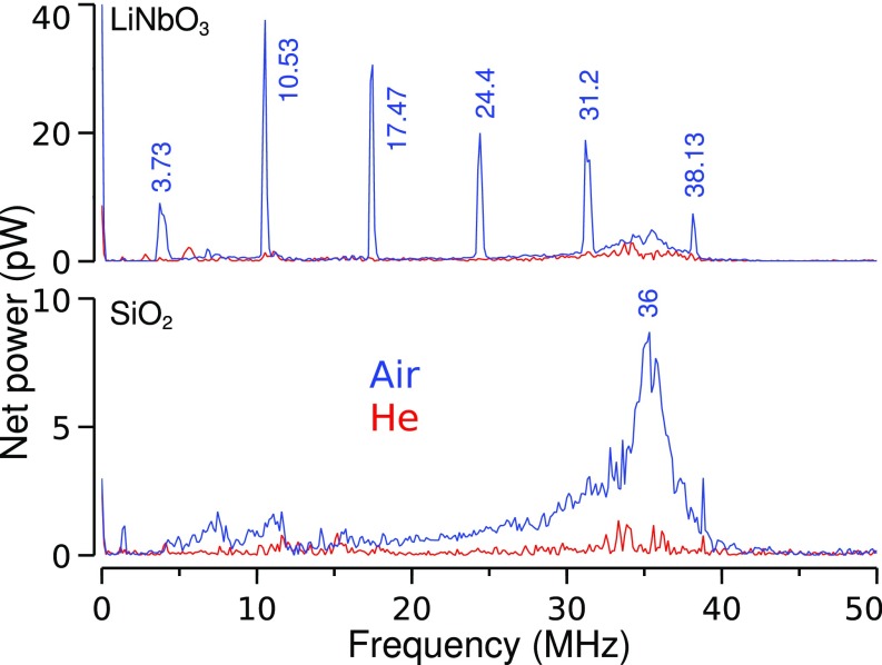
Radio-frequency (RF) measurements were performed using the antenna shown in Fig. S6. For the highly piezoelectric LiNbO3 (27), the RF power spectrum (Fig. 4) shows a strongly discrete content from MHz to with peaks at 6.8-MHz intervals. This was observed only in the presence of ionized air gas. The peaks are absent with the lesser piezoelectric SiO2 or when the gas is changed to helium. We also note a broader peak at about , present for both substrates and dominant in air.
Fig. 4.
RF spectra. Shown are power spectra of the RF signals, on SiO2 and on LiNbO3, concurrent with luminescence in air (blue line) and helium (red line). Jet velocity was .
The interaction of electrons with the heavy and positively charged ions is known to induce plasmas to oscillate in response to charge fluctuations (28). These oscillations, or Langmuir waves, are characterized by a plasma–electron frequency and by a plasma–ion frequency (SI Detailed Calculations). The latter is also the upper limit of longer-wavelength oscillations known as ion acoustic waves (29), the result of ions and electrons oscillating in phase and producing longitudinal density perturbations similar to sound waves in a gas. We conjecture (SI Detailed Calculations) that the -MHz peak is likely the signature of an ion acoustic wave instability with wavelength , a value in the scale range of the plasmoid documented here.
Finally, fluctuations in plasma shape (30) can induce oscillations distinct from the plasma–electron and plasma–ion oscillations. We suppose that the discrete peaks observed on LiNbO3 could originate from such plasma shape instabilities, triggered by a possible coupling with the piezoelectric modes of the material or by its pyro- and ferro-electric properties.
Physico-Chemical Characterization of Water.
The water was sampled at the edge of the wafer plates. In presence of the air plasma, the pH of water changed from to , respectively before and after corona onset and regardless of the wafer material. This corresponds to a -fold increase in concentration of cations from to . At jet speeds below corona onset, the pH remained unaffected with a value close to that of the impinging water.
Air plasmas are known to produce reactive oxygen and nitrogen species (3, 31, 32), specifically nitrites and nitrates . Assuming the existence of a source of energetic free electrons, several chemical reactions are suggested for our experiment (Table S1 A–H) that result in the formation of and ions; the concentration of defines the pH level. We show (SI Detailed Calculations) that the pH drops from to as a consequence of these reactions, a value in close agreement with the result from direct pH measurement. Therefore, the air plasma is the cause of water acidification.
At the interface (Table S1 I–O), bombardment of water molecules by ions accelerated by the electric field induces a secondary mechanism whereby solvated electrons are created via a chemical tunneling reaction (33) and released into the gas phase (SI Detailed Calculations). Generation of near-surface solvated electrons has been reported recently (34) with an atmospheric pressure air plasma over a water surface. This secondary pathway to electron emission is also a source of cations, hence affecting further the pH of water, and a source of •OH and •H radicals. No evidence of these latter species was found, suggesting that the free electrons in the gas phase carry less than the needed for the first excited state of •OH. This corroborates the 2.64-eV electron energy determined from spectroscopic analysis. Finally, associative ionization of nitrogen atoms (Table S1B) acts as an important source of ions and free electrons. This reaction is therefore relevant to the interface reactions and can promote both the electron density and the degree of ionization of the plasma.
In the case of the helium plasma, the water pH was found to be unaffected. However, the spectroscopic analysis revealed the presence of the OH radical and several lines of the hydrogen Balmer series (Fig. 2B). This suggests that the •OH and •H radicals and their ionic counterparts OH− and originate from the dissociation of water molecules in the flowing jet or from water vapor near the gas–liquid interface (Table S1 P–S). For this to occur, a bond-dissociating energy of is necessary. The water natural autodissociation (Table S1R) further contributes to the formation of these ionic species. As the cation bonds with into , the latter reverses into and and so forth, creating an acidic channel of solvated cations suitable for the transport of electrical current in water. The distinct chemical reactions for the air and for the helium plasmas are energetically congruent (SI Detailed Calculations), suggesting the existence of a unique source of energetic free electrons carrying about . We note that this estimate coincides with the electron temperature range established from optical emission spectroscopy.
Discussion and Summary
Upon these observations and analyses, we postulate a scenario for the plasma formation in air where the mechanism responsible for the electric field should be closely related to the interaction of the jet with the surface of the dielectric target. One possible candidate is a phenomenon known as streaming potential (35), which stems from the tribo-electric effect between two nonconducting materials in contact between them and put into relative motion (36).
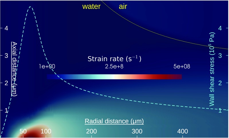
To verify this hypothesis, we first conducted numerical simulations of the impinging jet flow (SI Materials and Methods). The jet is seen to expand abruptly into a radial wall jet (37) through a sharp neck (Fig. S7). The fluid layer then goes through an extreme thinning, reaching a thickness of at a radius of followed by a gradual thickening. A highly concentrated region of extreme strain rate () is detected at from the jet axis and within from the wall (Fig. 5). The wall shear stress in this location reaches . Tribo-electric charging is likely to occur in this highly frictional and concentrated area.
Fig. 5.
Computational fluid dynamics simulation of the impinging jet flow. The color plot represents an area of and shows the strain rate, with the yellow line outlining the jet interface between liquid water and gas phase. We note the concentrated region of intense strain rate, approximately at from the jet axis and within from the wall. The cyan curve reports the radial distribution of the wall shear stress (right vertical axis), with a peak of .
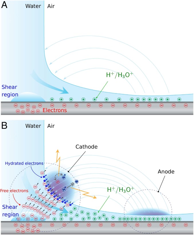
Silica-based materials are known to acquire a negative surface charge density when in contact with water (38). Therefore, we expect a negatively charged layer on the solid surface side balanced by a positively charged layer on the liquid side (schematic in Fig. 6A). As this positive layer is swept by the fast streaming flow, the narrow section of the radially expanding jet populates with positive charges eventually forming an anode site. In the high-shear region, the tribo-electric effect between deionized water and the already negatively charged dielectric surface promotes negative charge buildup. Nearest to this high-shear location and with the smallest radius of curvature of the free surface, the annular neck region has a tip-like geometry ideal for charge concentration (39), thus forming a cathode site. This anode–cathode configuration is congruent with the electric field topology shown in Fig. 3.
Fig. 6.
The scenario for tribo-electric charging and plasma generation in air. (A) The schematic depicts an early instant of flow over the dielectric quartz wafer, creating a weak electrostatic field represented by the light blue lines. Also shown is the initial formation of negative charges (red symbols) at the wafer surface and of positive charges (green symbols) in water from interaction with . combines with to form ions which accumulate in the narrow region (the anode). (B) As the flow speed elevates, free electrons are produced through the tribo-electric effect in the high-shear region. Electron collisions dissociate , thus creating that induce electrical conductivity in water. This allows the electrons to reach the free surface (the cathode) and pass into the gas phase. Through collisions the gas molecules are excited and/or ionized, forming the plasma. Concurrent dissociation of and triggers the formation of nitrites and nitrates in liquid water, inducing a surplus of solvated cations and consequent water acidification. A secondary electron emission mechanism takes place at the air–water interface from ion bombardment of molecules, whereby more cations are introduced into water and hydrated electrons (blue symbols) are produced and released into the plasma. Electrons are represented traveling along the electric field lines toward theanode.
In this scenario, the free electrons stemming from the high-shear region (Fig. 6B) collide and dissociate water molecules in a radiolysis-type process (40), producing hydroxyl and hydrogen radicals along with their ionic variants and enabling the transport of current from the high-shear location to the free surface in the annular neck region. The free electrons pass into the air gas phase, ionizing and splitting nitrogen and oxygen molecules, thus triggering the plasma occurrence. Furthermore, ion bombardment of water molecules at the air–water interface creates hydrated electrons, which are then released into the plasma phase. This interface mechanism is intensified by associative ionization reactions introducing additional ions and electrons. As a by-product of these processes, excess cations populate the liquid water phase in the cathode region, causing the acidification of water and eventually driving the transport of current from the substrate to the free surface. We conjecture that the buildup of cations in water inhibits the dissociation of liquid water molecules, halting the formation of hydroxyl and hydrogen radicals. Finally, hydronium cations are also transported toward the anode region where they accumulate to form and sustain the electric potential.
To complete the scenario, the free electrons surviving these events travel toward the anode through air along the electric field lines (Fig. 6B). Along the path, air molecules are excited and ionized through collisions in a Townsend-type avalanche process forming the air corona. A similar but weaker process occurs at the anode site, denoting the fact that the corona is negative at the cathode and positive at the anode. Evidence of intense spray generation at this location indicates that the positive charge concentration is strong enough to break up the thin liquid sheet into highly charged droplets (39, 41).
In the helium plasma case, dissociation of water molecules and excitation of He atoms are likely the only active mechanisms. Because the free electrons carry less than , He+ ions are not formed, thus preventing the onset of secondary electron emission mechanisms through ion bombardment that would otherwise enhance the electron density of the plasma. The water pH is also not affected as water dissociation is electrically balanced and external sources of cations are absent.
Finally, the electrostatic field, plasma, and RF analyses congruently support the idea of a self-induced electromagnetic field as a plausible explanation for the air plasma toroidal topology. Such a condition is normally associated with a self-generated space charge field (42), which occurs when free electrons and ions permeate the plasma cloud and strongly interact, as evidenced by the electron–ion collisional rate. This situation was verified with ionized nitrogen only and is supported by a RF signature compatible with plasma oscillations. We suppose that the high electron density and high degree of ionization could also arise from ions being confined by this self-generated electromagnetic field and into a microscale volume.
We tested this scenario through electrical grounding near the core region (SI Materials and Methods), thus increasing artificially the current density by injecting free electrons into the high-shear region. The test showed an increase in RF intensity and of the electric field strength. We also tested the stability and viability of the toroidal plasma, applying a potential between the wafer base and the jet nozzle tip. Surprisingly no disruption, damping, or amplification of the plasma structure was observed (Movie S2).
In summary, we have demonstrated the possibility to create a coherent plasma structure that is both chamberless and unconstrained by external forces, setting a unique paradigm in plasma physics. The study further shows that pure hydrodynamic shear can induce the dissociation of water molecules and the excitation and ionization of gas molecules. Another finding is the possible self-confinement of ions in the form of a toroidal microplasma, without externally applied electromagnetic fields.
This experimental study suggests the discovery of a unique platform to support new experimentation in the broad field of plasma science. The confined and chamberless nature of the plasmoid would allow one to probe the collisional state in greater detail and investigate more effectively the physics of plasma–liquid interactions (31) or of plasma scaling (5). The coupling of piezoelectric nonconductive materials with a dielectric liquid through tribo-electricity has not been reported to date. In that respect, the degree of accessibility and control offered by our coherent plasma platform can help investigate and probe the tribo-electric effect, a still not well-understood phenomenon, or the physics of solvated electrons (34). Our findings also suggest that exotic properties such as pyro-electricity (43) and ferro-electricity (44) could be explored to enhance the energy range of our plasma process and inspire new concepts of plasma devices for material processing or for the emerging field of plasma medicine (45). Our platform could also be of interest within the technological challenge of plasma self-confinement (46) or suggest pathways to create energy-storing coherent plasma structures at atmospheric pressure (47).
Supplementary Material
Acknowledgments
We thank B. Abiri, J. Adams, Prof. A. Hajimiri, S. Hufstedler, D. Jeon, J. Meier, K. Mendoza, D. Rinderknecht, and K. Sharafi, who in various stages of this project helped by participating in experiments or provided expertise for the diagnostics or experimental setup. We also thank Prof. P. M. Bellan for kindly reviewing the plasma analysis and for bringing the ion acoustic wave instability to our attention. The work was supported by California Institute of Technology internal funds and the Charyk Foundation. We dedicate the work to our late teacher and colleague Prof. Anatol Roshko.
Footnotes
The authors declare no conflict of interest.
This article is a PNAS Direct Submission.
This article contains supporting information online at www.pnas.org/lookup/suppl/doi:10.1073/pnas.1712717114/-/DCSupplemental.
References
- 1.de Camões LV. 1572. Os Lusíadas; trans Burton RF (1880) The Lusiads (Bernard Quaritch, London), Canto V, Stanza 18, p 185. Portuguese.
- 2.Dwyer JR, Uman MA. The physics of lightning. Phys Rep. 2014;534:147–241. [Google Scholar]
- 3.Keidar M. Plasma for cancer treatment. Plasma Sourc Sci Technol. 2015;24:033001. [Google Scholar]
- 4.Becker KH, Schoenbach KH, Eden JG. Microplasmas and applications. J Phys D Appl Phys. 2006;39:R55–R70. [Google Scholar]
- 5.Janasek D, Franzke J, Manz A. Scaling and the design of miniaturized chemical-analysis systems. Nature. 2006;442:374–380. doi: 10.1038/nature05059. [DOI] [PubMed] [Google Scholar]
- 6.Eden JG. Information display early in the 21st century: Overview of selected emissive display technologies. Proc IEEE. 2006;94:567–574. [Google Scholar]
- 7.Bruggeman P, Brandenburg R. Atmospheric pressure discharge filaments and microplasmas: Physics, chemistry and diagnostics. J Phys D Appl Phys. 2013;46:464001. [Google Scholar]
- 8.Schoenbach K, et al. Electrical breakdown of water in microgaps. Plasma Sources Sci Technol. 2008;17:024010. [Google Scholar]
- 9.Loeb LB. Electrical Coronas, Their Basic Physical Mechanisms. Univ of California Press; Berkeley: 1965. p. 694. [Google Scholar]
- 10.Cavaliere E, et al. High pressure rinsing parameters measurements. Physica C Supercond. 2006;441:254–257. [Google Scholar]
- 11.Miura T, Nakayama K. Two-dimensional spatial distribution of electric-discharge plasma around a frictional interface between dielectric surfaces. Appl Phys Lett. 2001;78:2979–2981. [Google Scholar]
- 12.Poulain C, Dugué A, Durieux A, Sadeghi N, Duplat J. The plasma levitation of droplets. Appl Phys Lett. 2015;107:064101. [Google Scholar]
- 13.Campanell MD, Laird JN, Provost T, Vasquez SW, Zweben SJ. Measurements of the motion of filaments in a plasma ball. Phys Plasmas. 2010;17:053507. [Google Scholar]
- 14.Lofthus A, Krupenie PH. The spectrum of molecular nitrogen. J Phys Chem Ref Data. 1977;6:113–307. [Google Scholar]
- 15.Grum F, Costa LF. Spectral emission of corona discharges. Appl Opt. 1976;15:76–79. doi: 10.1364/AO.15.000076. [DOI] [PubMed] [Google Scholar]
- 16.Bruggeman PJ, Sadeghi N, Schram DC, Linss V. Gas temperature determination from rotational lines in non-equilibrium plasmas: A review. Plasma Sourc Sci Technol. 2014;23:023001. [Google Scholar]
- 17.Sasaki S, Takamura S, Kato T. Effective ionization and emission rate coefficients of the helium atom in a plasma. Fusion Eng Des. 1997;34–35:747–750. [Google Scholar]
- 18.Griem HR, Shen KY. Stark broadening of hydrogenic ion lines in a plasma. Phys Rev. 1961;122:1490–1496. [Google Scholar]
- 19.Griem HR, Baranger M, Kolb AC, Oertel G. Stark broadening of neutral helium lines in a plasma. Phys Rev. 1962;125:177–195. [Google Scholar]
- 20.Nikiforov AY, Leys C, Gonzalez MA, Walsh JL. Electron density measurement in atmospheric pressure plasma jets: Stark broadening of hydrogenated and non-hydrogenated lines. Plasma Sourc Sci Technol. 2015;24:034001. [Google Scholar]
- 21.Laux CO, Spence TG, Kruger CH, Zare RN. Optical diagnostics of atmospheric pressure air plasmas. Plasma Sourc Sci Technol. 2003;12:125–138. [Google Scholar]
- 22.Britun N, et al. Determination of the vibrational, rotational and electron temperatures in and rf discharge. J Phys D Appl Phys. 2007;40:1022–1029. [Google Scholar]
- 23.Paris P, et al. Intensity ratio of spectral bands of nitrogen as a measure of electric field strength in plasmas. J Phys D Appl Phys. 2005;38:3894–3899. [Google Scholar]
- 24.Huba JD. 2004. NRL: Plasma formulary (Naval Research Laboratory, Washington, DC), Technical Report NRL/PU/6790–04–477.
- 25.Rajasekaran P, Bibinov N, Awakowicz P. Quantitative characterization of a dielectric barrier discharge in air applying non-calibrated spectrometer, current measurement and numerical simulation. Meas Sci Technol. 2012;23:085605. [Google Scholar]
- 26.Cserfalvi T, Mezei P. Operating mechanism of the electrolyte cathode atmospheric glow discharge. J Anal Chem. 1996;355:813–819. doi: 10.1007/s0021663550813. [DOI] [PubMed] [Google Scholar]
- 27.Sanna S, Schmidt WG. Lithium niobate X-cut, Y-cut, and Z-cut surfaces from ab initio theory. Phys Rev B. 2010;81:214116. [Google Scholar]
- 28.Tonks L, Langmuir I. Oscillations in ionized gases. Phys Rev. 1929;33:195–210. [Google Scholar]
- 29.Fenneman DB, Raether M, Yamada M. Ion-acoustic instability in the positive column of a helium discharge. Phys Fluids. 1973;16:871–878. [Google Scholar]
- 30.Tonks L. Plasma-electron resonance, plasma resonance and plasma shape. Phys Rev. 1931;38:1219–1223. [Google Scholar]
- 31.Bruggeman P, Leys C. Non-thermal plasmas in and in contact with liquids. J Phys D Appl Phys. 2009;42:053001. [Google Scholar]
- 32.Liu ZC, et al. Physicochemical processes in the indirect interaction between surface air plasma and deionized water. J Phys D Appl Phys. 2015;48:495201. [Google Scholar]
- 33.Hart EJ, Anbar M. The Hydrated Electron. Wiley-Interscience; New York: 1970. p. 267. [Google Scholar]
- 34.Rumbach P, Bartels DM, Mohan Sankaran R, Go DB. The solvation of electrons by an atmospheric-pressure plasma. Nat Commun. 2015;6:7248. doi: 10.1038/ncomms8248. [DOI] [PMC free article] [PubMed] [Google Scholar]
- 35.Varga IK, Seymour RS. Observation of electrical effects with cavitating liquid flow. J Phys D Appl Phys. 1986;19:2293–2300. [Google Scholar]
- 36.Ravelo B, Duval F, Kane S, Nsom B. Demonstration of the triboelectricity effect by the flow of liquid water in the insulating pipe. J Electrostat. 2011;69:473–478. [Google Scholar]
- 37.Lienhard JH. Liquid Jet Impingement. Vol 6. Begell House; New York: 1995. pp. 199–270. [Google Scholar]
- 38.Behrens SH, Grier DG. The charge of glass and silica surfaces. J Chem Phys. 2001;115:6716–6721. [Google Scholar]
- 39.Collins RT, Jones JJ, Harris MT, Basaran OA. Electrohydrodynamic tip streaming and emission of charged drops from liquid cones. Nat Phys. 2008;4:149–154. [Google Scholar]
- 40.Schwarz HA. Free radicals generated by radiolysis of aqueous solutions. J Chem Educ. 1981;58:101–105. [Google Scholar]
- 41.Miljkovic N, Preston DJ, Enright R, Wang EN. Electrostatic charging of jumping droplets. Nat Commun. 2013;4:2517. doi: 10.1038/ncomms3517. [DOI] [PubMed] [Google Scholar]
- 42.Bostick WH. Experimental study of plasmoids. Phys Rev. 1957;106:404–412. [Google Scholar]
- 43.Brownridge JD, Shafroth SM. Self-focused electron beams produced by pyroelectric crystals on heating or cooling in dilute gases. Appl Phys Lett. 2001;79:3364–3366. [Google Scholar]
- 44.Rosenman G, Shur D, Krasik YE, Dunaevsky A. Electron emission from ferroelectrics. J Appl Phys. 2000;88:6109–6161. [Google Scholar]
- 45.Yan D, et al. Principles of using cold atmospheric plasma stimulated media for cancer treatment. Sci Rep. 2015;5:18339. doi: 10.1038/srep18339. [DOI] [PMC free article] [PubMed] [Google Scholar]
- 46.Binderbauer MW, et al. A high performance field-reversed configuration. Phys Plasmas. 2015;22:056110. [Google Scholar]
- 47.Smirnov BM. Physics of ball lightning. Phys Rep. 1993;224:151–236. [Google Scholar]
- 48.Bellan PM. Fundamentals of Plasma Physics. Cambridge Univ Press; Cambridge, UK: 2008. p. 536. [Google Scholar]
- 49.Herbert JM, Coons MP. The hydrated electron. Annu Rev Phys Chem. 2017;68:447–472. doi: 10.1146/annurev-physchem-052516-050816. [DOI] [PubMed] [Google Scholar]
- 50.Buxton GV, Greenstock CL, Helman WP, Ross AB. Critical review of rate constants for reactions of hydrated electrons, hydrogen atoms and hydroxyl radicals (•OH/•O−) in aqueous solution. J Phys Chem Ref Data. 1988;17:513–886. [Google Scholar]
- 51.Siefermann KR, et al. Binding energies, lifetimes and implications of bulk and interface solvated electrons in water. Nat Chem. 2010;2:274–279. doi: 10.1038/nchem.580. [DOI] [PubMed] [Google Scholar]
- 52.Mezei P, Cserfalvi T. Electrolyte cathode atmospheric glow discharges for direct solution analysis. Appl Spectrosc Rev. 2007;42:573–604. [Google Scholar]
Associated Data
This section collects any data citations, data availability statements, or supplementary materials included in this article.


