Abstract
Total knee arthroplasty (TKA) is a common procedure in the United States; it has been estimated that about 4 million people are currently living with primary knee replacement in this country. Despite huge improvements in material properties, implant design, and surgical techniques, some implants fail a few years after surgery. A lack of information about in vivo kinetics of the knee prevents the establishment of a correlated intra- and postoperative loading pattern in knee implants. In this study, a conceptual design of an ultra high molecular weight (UHMW) knee bearing with embedded piezoelectric transducers is proposed, which is able to measure the reaction forces from knee motion as well as harvest energy to power embedded electronics. A simplified geometry consisting of a disk of UHMW with a single embedded piezoelectric ceramic is used in this work to study the general parametric trends of an instrumented knee bearing. A combined finite element and electromechanical modeling framework is employed to investigate the fatigue behavior of the instrumented bearing and the electromechanical performance of the embedded piezoelectric. The model is validated through experimental testing and utilized for further parametric studies. Parametric studies consist of the investigation of the effects of several dimensional and piezoelectric material parameters on the durability of the bearing and electrical output of the transducers. Among all the parameters, it is shown that adding large fillet radii results in noticeable improvement in the fatigue life of the bearing. Additionally, the design is highly sensitive to the depth of piezoelectric pocket. Finally, using PZT-5H piezoceramics, higher voltage and slightly enhanced fatigue life is achieved.
Keywords: Total knee replacement, embedded sensors, piezoelectric sensing, UHMW fatigue, energy harvesting, orthopedic implant
1. Introduction
Total knee arthroplasty (TKA) is almost as prevalent as congestive heart failure; it has been estimated that about 4 million people with primary TKA, and more than 500,000 with revision of primary TKAs currently live in the United States. This population is part of the estimated 11 million people who have been diagnosed with symptomatic knee osteoarthritis [1]. Today, more than 150 implant types exist which try to provide more natural geometry, wear and fatigue resistance, and functionality [2]. Functionality of TKA is highly dependent on compromises between stability and flexibility which can be provided by adequate ligament alignment techniques. Several proven methods have been established to guarantee component alignment and position in knee surgery, however, ligament balancing still remains more art than science and is performed based on the assessment of the surgeon according to tactile feedback [3].
Loosening, infection, and instability have been reported as the most common reasons for knee failure, and instability has been a consistent factor in the literature for knee revision surgery during the last decade [4]. Instability is directly dependent on operative factors such as improper fixation or misalignment, and mostly occurs due to lack of proper medial and lateral ligament tensioning [5]. It is estimated that about 40% of knee replacement failures can be avoided with proper fixation and optimal balancing at the time of surgery [4]. Nowadays, in spite of comprehensive studies on the importance and significance of a balanced TKA, optimal balance is not fully quantified [3]. In fact, lack of information about in vivo force reactions, which represent the force loads experienced by the patients, preclude establishing a comprehensive correlation of intraoperative loading to postoperative loading [3, 6].
In order to tackle the above mentioned limitations, researchers have presented several instrumented implants to obtain in vivo data for the optimization of TKAs. Despite abundant efforts on the development of instrumented implants, only two research groups have developed instrumented TKA implants that were actually used in preclinical trials in the human body [7]. The first trial was performed by D’Lima et al. in 2001 [8], and the second was performed by Heinlein et al. in 2007 [9]. Both designs consist of instrumented tibial trays customized for monitoring knee loads. The first design of D’Lima included modifications in the tibial tray such as a hollowed stem containing circuits and a telemetry system, a modified tibial tray plate to insert four load cells, and an additional upper plate. Shortly after, they modified the design to use 12 strain gauges located in the stem of the tibial tray to improve load measuring abilities. In the work of Heinlein, a standard hollowed implant was installed inside an enlarged tibial tray to utilize 6 strain gauges, a temperature sensor, circuits, and a telemetry system. Both of the discussed architectures employed inductive powering using an external coil placed around the patient’s knee to power the measurement and telemetry systems.
In addition to these implemented architectures, some other prototypes have been proposed by several researchers which were not applied in the human body. Almouahed et al. presented a design, based on D’Lima’s initial design, which contains four piezoelectric ceramics to obviate the dependency of the device on an external power source [10]. The implant, with a modified tibial tray to incorporate the piezoelectrics and additional tray thickness compared to the original implant dimension, aimed to measure compression forces of the knee joint as well as harvest energy to power electrical circuits and a telemetry system [11]. The proposed design can generate 6.265 mW of power under normal walking gait. In the work performed by Luciano et al. [12], an electromagnetic-based sensing and energy harvesting mechanism was presented to be utilized in knee implants. The system consisted of 2 series of 6 magnets located in the femoral component of the knee and a wire coil inside the polyethylene bearing of the tibial component to harvest necessary power for electrical components, and another 3 magnetoresistive sensors to measure the compression force in the knee joint. The system can provide 92 μW of power, enough to provide the required power for a 1.7 mW telemetry and sensor system for 16 ms after 7.6 s of operation.
In order to counteract the limitations of current proposed designs in terms of external power sources which result in patient discomfort and modified bearing geometry that necessitate modification in prevalent surgical techniques including soft tissue alignment, a novel conceptual design is suggested in this work. Figure 1 illustrates a schematic view of a total knee replacement and a UHMW bearing with four embedded lead zirconate titanate (PZT) transducers (note, requisite electronics for data collection/transmission are not shown). Embedded piezoelectrics in the bearing allow measurement of compartmental forces and location of contact areas as well as energy harvesting from knee motion. In addition, the piezoelectric transducers are able to provide structural health monitoring capability of the knee implant, which has not been presented in previous designs of instrumented knee implants and will be a focus of our future work. The envisioned function of the proposed system is to harvest energy throughout the day during normal daily activities and use the energy to power the sensory and data transmitting system once per day. Similar multi-mode functionality has been proposed in the literature [13]. Daily measurements can be used by surgeons and physical therapists to monitor and track the functionality of the patient’s knee replacement. Surgeons can use this information to update surgical procedures. Physical therapists can use this information to optimize and customize therapy. Additionally, data from groups of patients can be used by implant manufacturers to help improve the design of future knee replacements. Finally, it should be noted that the exact functionality of the instrumented system can be adjusted by surgeons and physical therapists to best suit their needs.
Figure 1.
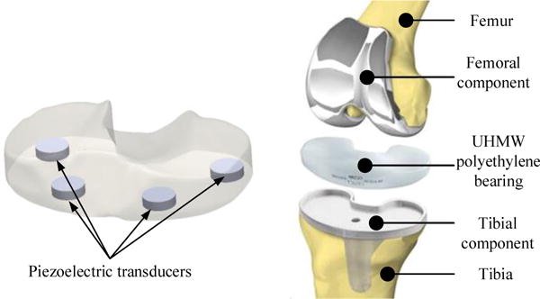
Schematic view of total knee replacement and proposed design of embedded PZTs inside the UHMW bearing.
Considering the conceptual design presented in Figure 1 which places PZT transducers within the UHMW bearing, the stress field inside the bearing is altered compared to the original (non-instrumented) component. As a result, the fatigue life of the instrumented bearing system should be investigated. Fatigue phenomenon often occurs in materials as a result of damage or propagation of a defect with a critical dimension. In the bearing component, fatigue life is related to the plastic flow parameters of UHMW such as yield stress and ultimate stress. Moreover, the existence of microscopic voids and defects affects the fatigue performance of the UHMW component [14]. Molecular parameters, the stress amplitude of the loading cycle, the mean stress, stress concentration, and initial defects are effective factors on the fatigue life of UHMW components. On the other hand, considering the brittle nature of piezoelectric ceramics, dynamic loading can lead to degradation in electromechanical properties as result of microscopic defects and initiated macroscopic cracks [15]. A study performed on a commercially available piezoelectric ceramic has shown an endurance limit of 60 MPa at 105 loading cycles [16], which is higher than the 15 MPa yield stress for UHMW material at the same number of cycles [17]. It will be shown in this work that the stress concentration occurs at the interface of the UHMW and PZT (see Sec. 6). Considering the continuity of tractions at this interface (hence equal shear and normal stresses on UHMW and PZT), the piezoelectric transducer has a higher fatigue resistance potential compared to the UHMW bearing under the same loading condition. Additionally, several durable commercial piezoelectric transducers have been introduced and utilized for long life applications; for instance, the PICMA piezoelectric transducer (PI Ceramic GmbH) [18] is used in the NASA Mars rover, Curiosity, and has been shown to operate up to 100 billion cycles (1011 cycles) without any reduction in electrical or mechanical properties.
In this study, a simplistic model used to represent a realistic knee bearing with an embedded piezoelectric transducer is proposed. A modeling framework consisting of finite element (FE) modeling of the instrumented bearing and analytical electromechanical modeling of piezoelectric ceramics is established to investigate the performance of the system. Initially, two submodels are proposed; one that places the PZT flush with the lower bearing surface and one that places the PZT fully embedded in the bearing. In order to evaluate the submodels, fabrication aspects and electromechanical performance of the systems are compared and the best design is chosen. The remainder of work focuses on the chosen model. In addition, the validity of the performed simulations is studied through an experimental test setup which is identical to the modeling setup for the chosen model. Moreover, a numerical parametric study on the effects of dimensional and material parameters on the fatigue life of the UHMW bearing and the electromechanical performance of the system is performed. The radius of fillet on the edges of PZT and pocket, the diameter and depth of PZT pocket, the proximity of PZT to the edge of UHMW bearing, the ratio of the thickness of PZT to the thickness of UHMW, and piezoelectric material properties are considered as factors that may affect performance. It should be noted that the fatigue analysis performed in this study focuses on the fatigue life of the UHMW bearing. The fatigue life of the PZT transducer itself will be investigated in future work.
2. Modeling framework
In this work, a simplified model of a total knee replacement bearing with a single embedded piezoelectric transducer (refer to Figure 1 for TKA components) is proposed. Two submodels are initially proposed, as shown in Figure 2, and consist of the flush design in Figure 2 (a) and the encapsulated design in Figure 2 (b). While a typical instrumented TKA would contain multiple sensors as well as electronics for data collection and transmission, the simple geometry investigated here containing one piezoelectric element provides a fundamental platform to study the general performance of the conceptual design. It should be noted that the results obtained in this study with regard to output voltage, output power, and longevity of the modified UHMW bearing do not provide an exact representation of the performance of the conceptual design due to the geometric simplifications, but allow the general trends in performance as a function of several parameters to be obtained from the parametric analysis explored in this work. The goal of this study, therefore, is to gain a general understanding of the effects of various parameters on the performance of the system in order to aid in the future design of instrumented knee bearings.
Figure 2.
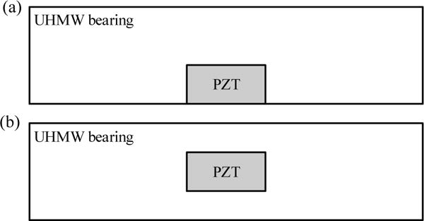
Cross-sectional view of UHMW and embedded PZT for (a) flush design and (b) encapsulated design.
2.1. Finite element and electromechanical modeling
The mechanical performance and stress-strain behavior of the proposed simplified bearing designs are studied using FE modeling. The system is modeled in ANSYS with 3D solid and contact elements for both the flush and encapsulated designs, shown in Figure 3 (a) and (b), respectively. Figure 3 (c) presents the analyzed components bounded by two flat fixtures which simulate the loading conditions experienced in experimental compression testing. SOLID187 elements for the bodies and CONTA14 elements for the contact areas are used. The generated mesh is finely sized for the bearing and PZT components and refined around the contact areas for both PZT and UHMW to ensure convergence in calculation of nodal forces. The boundary conditions are specified in a manner that satisfies the experimental setup conditions found in Sec. 4.1. The contact surfaces of both PZT and UHMW with the fixtures (located on both top and bottom surfaces) are modeled as frictionless, and the contact surface between PZT and UHMW is defined with a frictional contact having a coefficient of static friction of 0.12 [19]. The displacement of the fixtures is constrained in all directions except for the vertical direction to keep a symmetric loading condition. Both fixtures are modeled as steel flexible bodies and are meshed. It is necessary to note that the large relative thickness of the fixtures combined with the fact that steel is 200 times stiffer than UHMW makes a rigid-like behavior in the fixtures.
Figure 3.
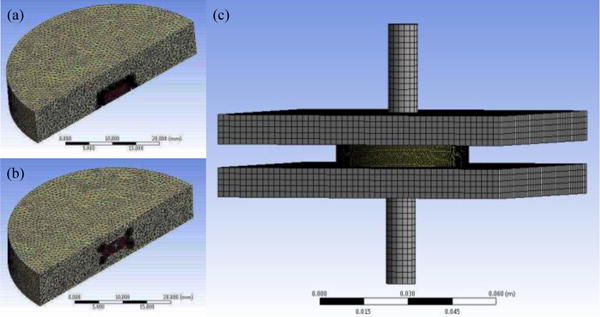
ANSYS finite element 3D models including (a) flush design, (b) encapsulated design, and (c) UHMW bearing with fixtures.
The material used for the polyethylene bearing is conventional UHMW polyethylene that is commonly used in knee implants, the material properties of which are listed in Table 1. The bearing dimension is 45 mm in diameter and 8 mm in thickness, which is close to the dimension of prevalent UHMW bearings [20]. On the bottom surface of the flush design bearing, a cylindrical pocket with 8 mm primary diameter and 3 mm primary depth is included to accommodate the PZT with an exact fit. For the encapsulated design with identical dimensional and material properties to the flush design, the pocket is placed in the mid-plane of the bearing.
Table 1.
Mechanical properties for UHMW bearing and PZT transducer ( ).
| Material Property | UHMW polyethylene | APC 850 (PZT-5A) | |
|---|---|---|---|
| Density | 930 |
7600
|
|
| Modulus of Elasticity | 0.689 GPa | 54 GPa | |
| Strain Constant, | – |
|
|
| Relative Dielectric Constant, | – | 1900 |
For the piezoelectric transducer, a piezoelectric made from APC International, Ltd. APC 850 with an 8 mm diameter and 3 mm thickness and poled across the thickness is used; the material properties of which are listed in Table 1. It is necessary to note that a monolithic piezoelectric transducer is used in the experimental study conducted in this work for validating the model according to transducer availability. PZT stacks (wired in parallel), however, have much higher capacitance and, therefore, much lower (more realistic) optimal load resistance values as well as higher voltage output compared to dimensionally identical monolithic PZTs, as discussed in the author’s previous work [21]. Due to the advantages of PZT stacks, they will be used in the numerical parametric study performed in this work.
The piezoelectric transducer is modeled as a passive material in FE. The effective force on the upper piezoelectric surface obtained from FE modeling is used to predict the electrical output of the transducer using an electromechanical constitutive model of piezoelectrics. MATLAB is used to predict the generated voltage and power, and the electromechanical model utilized in these calculations is described in the author’s previous work [21], but summarized here. The governing equation of an -layer piezoelectric stack under a uniform dynamic load with each layer connected electrically in parallel to a single resistive load is given by
| (1) |
where, t is time, is generated voltage, is resistive load, is applied force on the piezoelectric transducer, is the effective piezoelectric strain constant given by , where is the piezoelectric strain constant of a single layer and N is the number of layers, and is the effective piezoelectric capacitance given by
| (2) |
where, represents the dielectric constant, A is the cross-sectional area of the piezoelectric stack, and h is the individual layer thickness. Note, for a monolithic piezoelectric transducer, the number of layers is equal to and h is then the total thickness of the piezoelectric transducer.
A standard load profile for mechanical testing of artificial knee components has been developed by the International Standard Organization (ISO) under the ISO 14243-1 standard [22], however, recent studies have shown that it may not completely represent in vivo implant conditions [23, 24]. As a result, a load profile developed using OpenSim biomechanical simulation software for normal walking gait and presented in the author’s previous work [25], illustrated in Figure 4, is utilized in this work. In both simulation and experimental studies, this load profile is applied to the upper fixture, hence the entire knee load is applied to the instrumented UHMW bearing to achieve two further purposes. First, in future realistic designs with multiple embedded PZTs, the maximum achievable amount of applied force to all PZT elements is equal to the complete knee force. Second, future analysis on material behavior and longevity of the model depends on the developed stress under full loading conditions.
Figure 4.
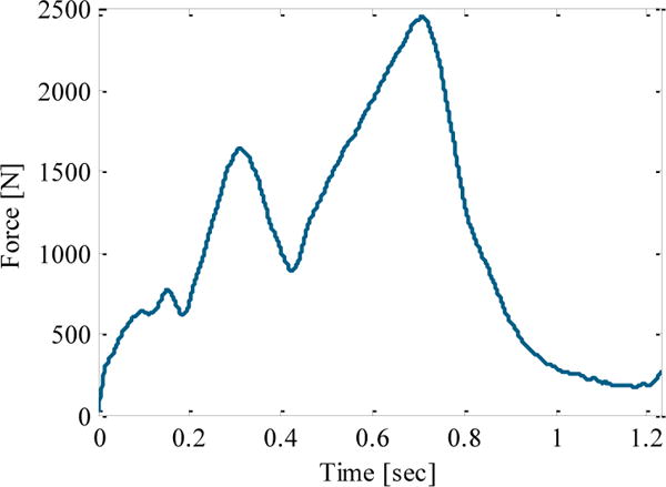
Load diagram for a standard gait predicted using OpenSim software and utilized throughout this study.
2.2. Fatigue analysis
In the study of the fatigue behavior of polymers, two distinct philosophies can be employed. The first method is the total life approach, which is usually used for non-critical applications and assumes that the material is initially defect-free. This method often applies for metals and stiff polymers with semi-linear elastic fracture mechanics [26]. In contrast, for soft material and elastomeric components with nonlinear behavior and large strains, the fatigue mechanics-based total life method is not always applicable to predict the longevity of material [27]. As a result, the second criteria is based on a defect tolerant approach in which the fatigue life of the component is defined as a function of the number of cycles needed to proliferate a crack with an initial size to a critical dimension [26].
In this work, in order to simulate fatigue behavior of the model under compressive loading, the total life philosophy is employed in ANSYS. Although the UHMW component is a relatively soft material with large strains and the total life method is not necessarily the best approach to predict the exact fatigue life, in terms of analyzing the effect of dimensional parameters on the fatigue behavior of the design, it can provide sufficiently comparable results, therefore, it is employed here. In order to perform the total life approach, the fatigue behavior of the material is characterized by the stress-life diagram, or curve, where S represents the stress amplitude and represents the number of cycles to failure at the stress amplitude of S [17]. The curve for conventional UHMW is plotted in Figure 5 in semi-logarithmic scale.
Figure 5.
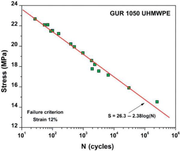
Representation of stress-life diagram for conventional UHMW [17]
The safety factor for stress life is utilized as the criteria to compare the effect of various dimensional parameters on the fatigue behavior of the proposed UHMW model. Safety factor is defined using Soderberg’s mean stress correction theory as:
| (3) |
where n is fatigue life safety factor, is alternative stress, is mean stress, is endurance limit stress from the diagram, and is yield stress. Larger safety factors provide a higher fatigue life (number of cycles).
3. Design evaluation
In this section, using the FE modeling procedure described in Sec. 2.1, the two submodels proposed in this study (flush and encapsulated designs) are first briefly compared in order to determine the best design, for which the remainder of the work will focus on. The submodels are compared with respect to electromechanical performance and fabrication aspects. The force applied to the top surface of the PZT transducer (obtained from FE analysis) directly affects the output of the system in terms of voltage and power. For the flush design, the amount of transferred force to the PZT is about 6.2% of the applied force to the system, whereas the same quantity for the encapsulated design is 5% of the applied force. The force vs. time response for both models acquired from FE analysis with the same material and boundary conditions is illustrated in Figure 6 for comparison. From the results, it can be seen that the flush design allows more force to be transferred to the embedded piezoelectric transducer, therefore, will provide better performance in terms of voltage generation (sensing ability) and energy harvesting.
Figure 6.
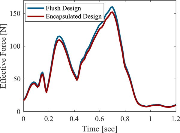
Comparison of obtained force transferred to PZT for flush and encapsulated designs.
In addition to investigating the electromechanical behavior of the two designs, various fabrication aspects should also be considered when choosing the best design. First, the fabrication process for the flush design includes simple machining to remove the pockets from the UHMW bearing for the transducers and required electronics. The fully encapsulated design, on the other hand, requires the transducers and electronics to be molded into the part or the use of a two-part bearing, therefore, the flush design would be easier to fabricate. Second, the surface mounted sensory system in the flush design would induce less change to the original design of the bearing and, as a result, less weakness in the UHMW material structure. Third, numerous techniques have been introduced to improve surface quality and wear resistance of the surfaces of UHMW bearings that can be implemented on the flush design to compensate for the negative effects of bearing modifications [28]. In conclusion, considering the abovementioned advantages of the flush design over the encapsulated design, the flush design is chosen in this study for further analysis of the electromechanical and fatigue performance of the system.
4. Experimental model validation
4.1. Test setup
A manufactured UHMW bearing with an embedded monolithic PZT transducer (made from APC 850, PZT-5A) is shown in Figure 7 (a)–(b). Although the advantages of PZT stacks have been previously discussed, given transducer availability, a monolithic PZT is utilized in the fabricated sample. The bottom surface of UHMW and PZT are flush with each other to provide a simultaneous loading condition on the UHMW and PZT, as described in the FE simulation. The sample is tested using an MTS 810 servo hydraulic load frame (Figure 7 (c)) under the realistic knee compression loading profile shown previously in Figure 4 with a 1 MΩ load resistor placed across the terminals of the PZT. The voltage generated from the PZT is acquired across the load resistance and stored using a National Instruments NI 9215 DAQ Card with a sampling rate of 1 kHz.
Figure 7.
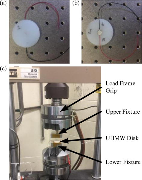
Fabricated sample (a) top view and (b) bottom view; (c) sample and fixtures installed in the MTS load frame.
4.2. Test result
In order to validate the employed FE and electromechanical models, modeling is performed for an embedded monolithic PZT, and a fabricated specimen is tested for one gait cycle using the load frame as described earlier. Figure 8 illustrates the experimentally measured voltage along with the simulated voltage predicted by FE and electromechanical modeling for comparison. The graph shows that the simulation and experimental results are in good conformity but not completely identical. The small deviation may be due to nonlinear elastic material behavior as well as small manufacturing tolerances, which have been simplified in the FE model. It is necessary to note that the system is strongly sensitive to the fabrication tolerances on the depth of the PZT pocket. The good correlation between simulation and experimental results validates the FE and electromechanical modeling framework and allows its use for the parametric study.
Figure 8.
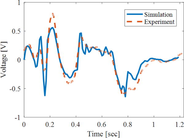
Comparison of the simulated and experimental voltage generation of an embedded monolithic PZT for a single gait period.
5. PZT stack performance
As previously discussed, piezoelectric stack transducers provide improved electromechanical performance compared to monolithic piezoelectrics. In this section, the validated modeling framework is used to simulate the performance of an embedded 50-layer PZT stack (APC 850, PZT-5A) with the same overall dimensions as used previously in this work (8 mm diameter, 3 mm thickness) in order to study the feasibility of using embedded piezoelectric transducers to harvest energy from the knee joint. Results of the simulation in terms of voltage and average power for various resistive loads for a single gait period are plotted in Figure 9 and Figure 10, respectively. The graphs show that a peak voltage of 3 V can be generated with a load resistor of 1 MΩ. Additionally, a peak average power of 5.5 μW can be obtained under a resistive load of 171 kΩ. The final design of an instrumented knee implant with four embedded piezoelectric transducers will incorporate a set of miniaturized electronics to achieve sensing, energy harvesting, and data transmission. The power requirement of such a system is highly dependent on the operational parameters such as the duty cycle of active sensing to energy harvesting, sampling rate, size of data collected, transceiver configuration and protocol, etc. With this in mind, exact power requirements cannot be defined in this preliminary work which focuses on the conceptual design of an embedded piezoelectric sensory system since circuitry has not yet been developed. For reference, previous work on low-power implantable measurement circuitry for biomedical applications has shown power requirements on the order of 30–45 μW for data collection [13]. Considering the target function of the instrumented implant developed in this work (harvesting throughout the day and sensing/data transmitting once per day) and employing four piezoelectric transducers in the knee bearing, these results show promising potential of embedded PZTs to supply power to a low power force measuring and telemetry system for knee implants.
Figure 9.
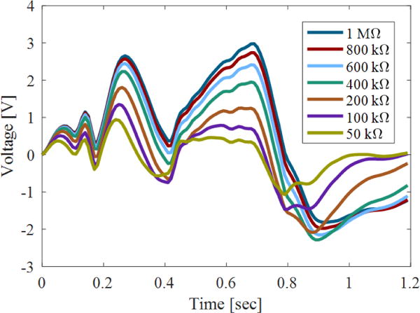
Simulated output voltage of an embedded 50-layer PZT stack for a single gait period under various resistive loads.
Figure 10.
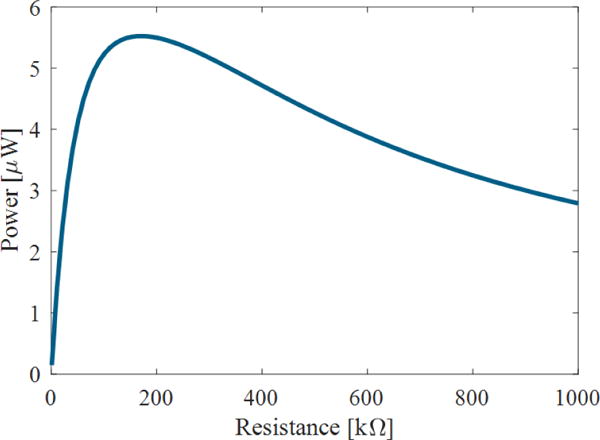
Generated power by an embedded 50-layer PZT stack as a function of resistive load.
6. Parametric study
A numerical parametric study is performed on the flush design with a 50-layer PZT stack to explore the effect of several dimensional and material parameters on the electromechanical and fatigue performance of the proposed system. Recall, the overall goal of this work is to gain a general parametric understanding of the effects of embedded PZT transducers on the performance of the system in order to aid in the future design of instrumented knee bearings. The simplistic model of UHMW with embedded PZT (Figure 3(a)) can provide a basis to investigate the effects of parametric variation on the general trends in performance of the system as long as the trends are independent of the overall bearing dimensions and externally applied loads. In other words, this work will investigate the local effects of the parameters in the vicinity of the PZTs. It is important to note that the results of this parametric study will not provide exact quantities of electromechanical and fatigue performance of an actual instrumented knee implant (which contains complex geometry and multiple embedded transducers), but will provide the general trends in performance of such a system as a function of the investigated parameters.
Fillet radius, pocket diameter, pocket depth, proximity of PZT to UHMW bearing edge, ratio of the thickness of PZT to the thickness of UHMW bearing, and material properties of PZT are considered as effective factors on the longevity of the UHMW component and the electromechanical performance of the system. Furthermore, the effects of these parameters are independent of the overall bearing geometry. Therefore, these parameters are selected as the independent parameters of interest in this study. It should be noted that the thickness ratio parameter can be used to simulate multiple effects including changes in the PZT height and/or the global bearing thickness as well as changes in the local bearing thickness arising from adjustment of the lateral location of the embedded PZT within a realistic bearing. Force transfer ratio to the PZT and generated voltage are considered as important factors to evaluate the sensing and energy harvesting ability of the system, therefore, they are investigated as the pertinent electromechanical system outputs for each parameter. Furthermore, the fatigue life safety factor provides a quantitative measure of the longevity of the system, therefore, it is investigated as the pertinent fatigue performance output for each parameter. In order to achieve convergence in the obtained stress quantities from the FE analysis, sharp corners (singularities) in the geometry should be avoided. Considering this, the sharp edges of the piezoelectric transducer and corresponding pocket in the UHMW bearing are modified in the FE model to include a very small fillet of 0.01 mm radius to allow convergence. With such a small fillet radius applied on the corners, this geometry still represents the case of relatively sharp corners and thus is referred to in this study as the design with sharp corners. Considering that the relatively sharp corner is the critical area for stress concentration, thereby causing a reduction in the fatigue life, the corner is then further modified in this study by increasing the fillet radius to create more rounded corners, as demonstrated in Figure 11. This latter model is referred to as the model with rounded corners. It is necessary to note that in the following sections, the peak voltage presented for all cases is obtained under a load resistance of 1 MΩ and that a single parameter is varied in each section.
Figure 11.
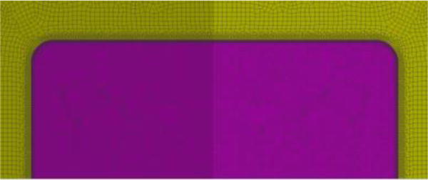
Modified corners of the UHMW and PZT by fillet radius.
6.1. Fillet radius
The sharp corner at the contact surface of the PZT and UHMW bearing is the critical region with maximum stress concentration which causes a remarkable reduction to the fatigue life in the model (safety factor of 0.64 for the model with sharp corners). Therefore, the sharp edge is modified by applying a fillet on the corners to evaluate the force transfer ratio, generated voltage, and fatigue life of the revised model as a function of fillet radius.
Figure 12 shows the trends in fatigue life safety factor (part a), and transferred force and peak voltage (part b) as a function of fillet radius. From the results, a rapidly increasing trend for the fatigue life safety factor is observed. Applying a fillet modification to the sharp corner of the bearing and PZT reduces the level of concentrated stress on the edges and improves the safety factor of fatigue life considerably. Fillet radii of 0.01 and 0.5 mm result in safety factors of 0.64 and 3.2, respectively. On the other hand, a slightly decreasing trend is observed for the transferred force ratio and peak voltage as the fillet radius increases.
Figure 12.
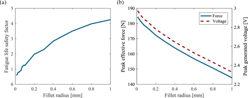
Effect of fillet radius on (a) safety factor of UHMW and (b) transferred force to the PZT and peak generated voltage.
Based on the simulation results for various fillet radii, which show that increases in the radius result in a compromise between improved fatigue life and decreased electromechanical performance, a very small fillet radius of 0.01 mm (denoted as sharp) and a relatively large fillet radius of 0.5 mm (denoted as rounded) are chosen for further parametric studies in the following sections.
6.2. Pocket diameter
Various pocket diameters starting from 8 mm for the initial model (which provides a fit tolerance between PZT and UHMW) to 9 mm (which provides 1 mm clearance between PZT and UHMW) are simulated and the variation of the fatigue life safety factor and the force transfer ratio and generated peak voltage are plotted in Figure 13 (a) and (b), respectively. The graphs are provided for the geometries with sharp (0.01 mm fillet radius) and rounded (0.5 mm fillet radius) corners. The fatigue life results presented in Figure 13 (a) show that the models with sharp corners and rounded corners exhibit an opposite behavior; pocket diameter enlargement results in an increase in the fatigue safety factor for sharp corners, but in a decrease for rounded corners. However, for both geometries, after about 0.2 mm pocket enlargement, the fatigue life safety factor converges to around 1.25. This phenomenon can be contributed to the governing mechanism of stress concentration in the UHMW material, which is the key factor in fatigue life and is explained in the following paragraph.
Figure 13.
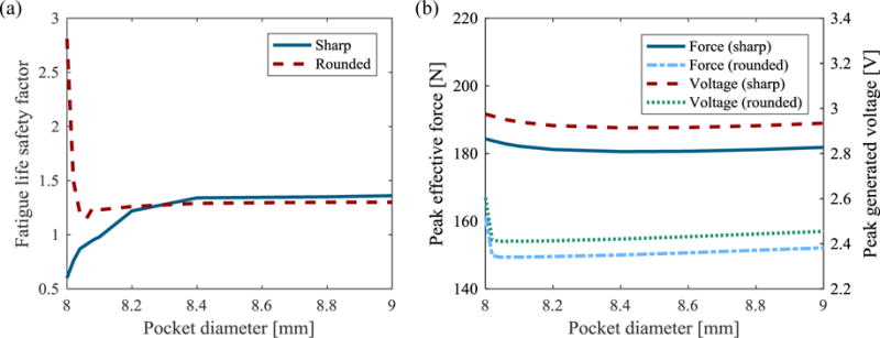
Effect of pocket diameter on (a) safety factor of UHMW and (b) transferred force to the PZT and generated peak voltage.
The stress concentration on the UHMW is created through two effects; first, the corner itself results in a stress concentration, and second, contact between the UHMW and the PZT results in a stress concentration on the edge of the PZT and the corresponding contact area of the UHMW. The stress concentration region movement as a function of growth in pocket diameter is demonstrated in Figure 14 and Figure 15 for sharp and rounded corner designs, respectively. For the sharp corner design, the stress concentration is induced by both mechanisms and is relatively high due to the sharp geometry of the corner and contact area. Additionally, the two concentrated stresses are collocated and have an additive effect, therefore, resulting in a high level of stress (therefore, low fatigue safety factor). When increasing the pocket diameter in the sharp corner design, the two stress concentration areas shift away from each other, thereby reducing the maximum local stress concentration in the system since the mechanism is no longer collocated/additive, thus resulting in improved fatigue safety factor. On the other hand, for the rounded corner design, the stress concentrations induced by the corner and the contact area are both relatively low due to the rounded geometry of the corners (more distributed stress and contact area). From Figure 15 (a), it can also be observed that these two stress concentrations are not collocated. The low stress concentrations and their spatial separation result in a low level of concentrated stress (therefore, high fatigue safety factor). Enlarging the pocket in the rounded corner design, however, disrupts the relatively even distribution of stress in the region near the rounded corner and causes a concentrated stress region to form at the contact point. This newly formed stress concentration at the contact point is similar to the contact behavior observed in the sharp corner design and results in higher (more concentrated) stress levels (therefore, lower fatigue safety factor). In addition, it can be concluded that the concentrated stress for enlarged pocket designs is mostly affected by contact mechanics rather than the corner edges of the UHMW pocket, thereby providing justification for the convergence of the fatigue life safety factor for increasing pocket diameters.
Figure 14.
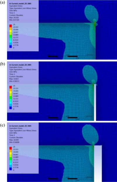
Shift of stress concentration region for various pockets of (a) 8 mm, (b) 8.1 mm, and (c) 8.4 mm diameter, for design with sharp corners (section view).
Figure 15.
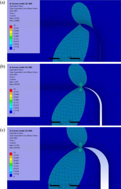
Shift of stress concentration region for various pockets of (a) 8 mm, (b) 8.1 mm, and (c) 8.4 mm diameter, for design with rounded corners (section view).
Considering the electromechanical performance as a function of pocket diameter, it can be seen from Figure 13 (b) that the force transferred to the PZT and the generated peak voltage experience little change with the variation of pocket diameter. The peak effective force and generated voltage demonstrate a slight decrease as the pocket diameter increases from 8 mm to 8.1 mm, and gradually rise with diameters more than 8.1 mm.
6.3. Pocket depth
Pocket depths ranging from 2.7 mm (a shallow pocket where the PZT protrudes below the bottom surface of the UHMW bearing) to 4 mm (a deep pocket whereby a gap is formed between the upper surface of the PZT and the corresponding UHMW bearing surface) are investigated next. Figure 16 (a) and (b) represent the fatigue life safety factor, and transferred force to the PZT and peak voltage for various pocket depths, respectively. It can be seen from the graphs that changes in the pocket depth have a significant effect on fatigue life, transferred force to the PZT, and generated voltage for both sharp corner and rounded corner designs. Minor increases in pocket depth (from the reference quantity of 3 mm) result in a remarkable increase in the amount of fatigue life, however, no force is transferred to the PZT in this case (hence, zero generated voltage). In this condition, the contact between the UHMW and PZT vanishes and the stress concentration is just produced from the corners of the pocket, so lower stress levels and higher fatigue life safety factors are obtained.
Figure 16.
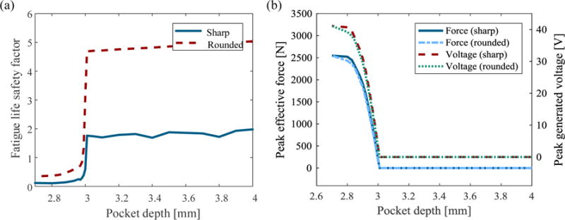
The effect of different pocket depths on (a) safety factor of UHMW and (b) transferred force to the PZT and generated peak voltage.
On the other hand, small decreases in the pocket depth bring out an exceptional decrease in the fatigue life but a remarkable increase in the amount of transferred force to the PZT and generated voltage. Higher obtained force quantities on the contact area of the UHMW and PZT result in increases in the stress concentration level, thereby, having a negative effect on the fatigue life performance of the design. It should be noted that this phenomenon has been experimentally observed in the author’s previous work on a similar system in terms of voltage output [25], which helps to validate the numerical results obtained here.
6.4. Proximity of PZT to the edge
The variation in fatigue life safety factor, and peak effective force on the piezoelectric transducer and peak generated voltage for different proximities of PZT to the bearing edge are plotted in Figure 17 (a) and (b), respectively. The proximities mentioned in this section are measured from the edge of the UHMW disk to the near edge of the PZT; the horizontal axis of the diagram starts from a proximity of 2 mm and extends to 18 mm (which is the center location of the bearing). For both cases (sharp and rounded corners), the quantities of all parameters (safety factor, force, and voltage) are almost independent of the proximity of the piezoelectric transducer to the UHMW bearing edge. There is a slight reduction in the quantities of transferred force to the PZT when the transducer is located near the edges of the UHMW disk, which can be contributed to the edge effect on the stress distribution inside the disk (stress flow density is slightly lower near the edges).
Figure 17.
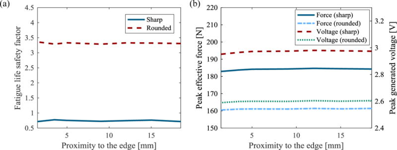
The effect of different PZT proximities to the bearing edge on (a) safety factor of UHMW and (b) transferred force to the PZT and generated peak voltage.
6.5. Thickness ratio
In this section, the overall thickness of the UHMW bearing is held constant at the reference quantity of 8 mm and the PZT thickness (and, correspondingly, pocket depth) is varied from 3 mm down to 1 mm, and the stress life, transferred force to the PZT, and generated peak voltage of the bearing are investigated. It is expected that thicker PZT elements will present greater effects on the distribution of stress within the bearing. The trends of change in fatigue safety factor, and transferred force to the PZT and generated peak voltage for different PZT thicknesses are plotted in Figure 18 (a) and (b), respectively. The results demonstrate that a reduction in the thickness ratio of PZT to UHMW increases the safety factor slightly. In contrast, reductions in thickness ratio cause a more significant decrease in the force transfer ratio and produced voltage.
Figure 18.
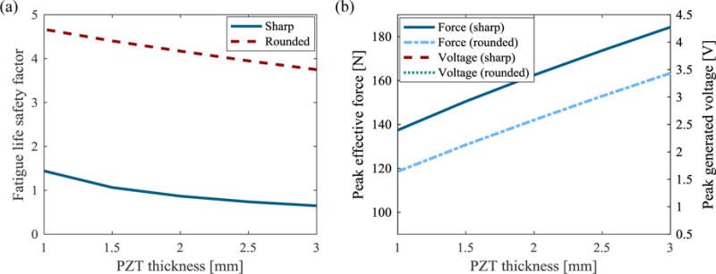
Effect of thickness ratio on (a) safety factor of UHMW and (b) transferred force to the PZT and generated peak voltage, for a UHMW bearing of 8 mm thickness.
6.6. Piezoelectric material
Several different piezoelectric materials are investigated in order to determine the ideal material for sensing and energy harvesting under compressive load. Piezoelectric stacks are simulated for four common piezoelectric materials including hard piezoceramics (PZT-4, PZT-8), and soft piezoceramics (PZT-5A, PZT-5H). Table 2 provides relevant material properties for each material considered (properties taken from APC International Ltd.). For consistency with the previous simulation results, each stack has 50 layers and an overall height of 3 mm. Due to the fact that dimensional parameters in this section are held constant, the simulation is performed only for the rounded corner design. Figure 19 (a) and (b) show the fatigue safety factor, and peak transferred force to the PZT and peak generated voltage by each material, respectively. It can be seen that both of the mechanical performance parameters (fatigue life and transferred force to the PZT) experience a very small change with variation in piezoelectric material type. Because of the relatively low elasticity modulus of PZT-5H, the amount of transferred force to the transducer is, however, slightly lower than the other materials. On the other hand, due to the higher piezoelectric constant of PZT-5H, the generated voltage from this material is significantly higher than the other materials.
Table 2.
Material properties of various APC piezoelectric materials ( ).
| Piezoelectric Material | PZT-4 (APC 840) | PZT-5A (APC 850) | PZT-5H (APC 855) | PZT-8 (APC 880) |
|---|---|---|---|---|
| Young’s Modulus (GPa) | 68 | 54 | 51 | 72 |
| Poisson’s Ratio | 0.42 | 0.42 | 0.42 | 0.42 |
| Piezoelectric Constant, | 290 | 400 | 630 | 215 |
| Relative Permittivity, | 1275 | 1900 | 3300 | 1050 |
Figure 19.
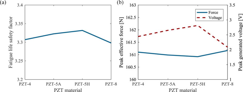
Effect of PZT material on (a) safety factor of UHMW and (b) transferred force to the PZT and generated peak voltage, for rounded corner design.
7. Discussion
The results obtained from the parametric study on the simplistic UHMW bearing with embedded PZT transducer presented in Sec. 6 can be utilized to understand the effect of each parameter on the general trends in performance of an instrumented knee implant. A summary of the findings and a brief discussion of their importance is given in the following for each parameter.
Fillet Radius: Applying a fillet on the sharp corners results in a small reduction in transferred force to the PZT and in generated voltage, but a remarkable improvement in fatigue life of the UHMW bearing. Based on these results, it is observed that incorporation of a fillet is essential to the design of an instrumented implant in order to improve fatigue life.
Pocket Diameter: Enlargement of the pocket diameter causes an increase in fatigue life of the sharp corner design and a decrease in the fatigue life of the rounded corner design, whereas the effect of pocket diameter on the electromechanical behavior of the embedded PZT is negligible. Considering the fact that it has been shown that a fillet should be used in the design, the pocket diameter should be selected to provide a tight fit between the PZTs and the bearing.
Pocket Depth: The pocket depth is the most critical factor among the parameters in terms of both fatigue life and electromechanical performance. A slightly shallower pocket results in very poor fatigue life but greatly enhanced electromechanical performance. In contrast, a slightly deeper pocket has the opposite effect on the behavior of the system. Based on these findings, the pocket depth must be carefully designed and must have highly precise machining tolerance during fabrication.
Proximity to Edge: The proximity of the PZT to the bearing edge has a negligible effect on fatigue life, effective force on the PZT, and generated voltage. These results are beneficial in terms of the eventual design of an instrumented bearing containing multiple PZTs since the lateral location can be freely adjusted for optimal sensing performance without any negative effects of the edges on fatigue life.
Thickness Ratio: Decreasing the thickness ratio of PZT to UHMW (i.e. decreasing PZT thickness while holding overall UHMW thickness constant) causes moderate effects on the performance of the system with slight improvement to fatigue life but slight decrease in force transfer and generated voltage. When designing an instrumented bearing, therefore, the PZT thickness should be chosen to be as small as possible while still meeting the electrical requirements of the system in terms of voltage (for sensing) and power.
PZT Material: Comparing four contemporary PZT ceramics including PZT-4, PZT-5A, PZT-5H, and PZT-8, it is observed that PZT-5H exhibits higher generated voltage and slightly improved fatigue life compared to the other materials. This is due to the fact that PZT-5H is the softest of these materials but also exhibits higher coupling, thereby making it the best material choice.
8. Conclusion
The aim of this work is to parametrically investigate the performance of instrumented total knee replacement bearings containing piezoelectric transducers (PZTs) for in vivo sensing of knee loads as well as harvesting energy to power embedded sensor electronics. In order to achieve this goal, a simplistic model of a UHMW knee bearing disk with an embedded piezoelectric transducer is proposed. In order to investigate the durability and electromechanical performance of the system under realistic knee loading conditions, a modeling framework including finite element analysis and electromechanical modeling is established. Originally, two submodels are investigated; the bearing with a PZT flush with the bottom surface, and the bearing with an entirely encapsulated PZT. The flush design is shown to have superiority over the encapsulated design, therefore, it is chosen for the remainder of study. Next, the modeling framework is validated through experimental testing of a prototype bearing. The validated model is then used to predict the sensing and energy harvesting performance of an embedded 50-layer PZT-5A stack subjected to realistic knee loads. Simulation results predict that a peak voltage of 3 V can be generated with a load resistor of 1 MΩ, and a peak average power of 5.5 μW can be obtained under a resistive load of 171 kΩ. Considering power consumption of existing low-power electronics for in vivo measurement, this level of power is adequate for operation on a fixed duty cycle, thus demonstrating the feasibility of self-powered instrumented knee implants. The model is then utilized for a parametric study on the effects of dimensional and material properties on the fatigue life and electrical output of the proposed system. To summarize the findings, the depth of the PZT pocket is found to be the most critical parameter on both electromechanical performance and fatigue life. Additionally, incorporation of a fillet on the corners of the PZT/UHMW interface provides significantly improved fatigue life with slight reduction in electrical output. Finally, PZT-5H is found to provide the highest safety factor and electromechanical performance. The results presented in this parametric study can be employed in future studies on a realistic instrumented knee implant design with multiple piezoelectric transducers in order to achieve enhanced electromechanical and durability performance.
Acknowledgments
Research reported in this publication was supported by the National Institute of Arthritis And Musculoskeletal And Skin Diseases of the National Institutes of Health under Award Number R15AR068663. The content is solely the responsibility of the authors and does not necessarily represent the official views of the National Institutes of Health.
References
- 1.Weinstein AM, Rome BN, Reichmann WM, Collins JE, Burbine SA, Thornhill TS, Wright J, Katz JN, Losina E. Estimating the burden of total knee replacement in the United States. Journal of bone & Joint Surgery. 2013;95:385–92. doi: 10.2106/JBJS.L.00206. [DOI] [PMC free article] [PubMed] [Google Scholar]
- 2.Carr BC, Goswami T. Knee implants–Review of models and biomechanics. Materials & Design. 2009;30:398–413. [Google Scholar]
- 3.Meneghini RM, Ziemba-Davis MM, Lovro LR, Ireland PH, Damer BM. Can Intraoperative Sensors Determine the “Target” Ligament Balance? Early Outcomes in Total Knee Arthroplasty. The Journal of arthroplasty. 2016;31:2181–7. doi: 10.1016/j.arth.2016.03.046. [DOI] [PubMed] [Google Scholar]
- 4.Sharkey PF, Lichstein PM, Shen C, Tokarski AT, Parvizi J. Why are total knee arthroplasties failing today—has anything changed after 10 years? The Journal of arthroplasty. 2014;29:1774–8. doi: 10.1016/j.arth.2013.07.024. [DOI] [PubMed] [Google Scholar]
- 5.Scuderi GR, Tria AJ. Knee Arthroplasty Handbook: Techniques in Total Knee and Revision Arthroplasty. Springer Science & Business Media; 2006. [Google Scholar]
- 6.Gustke KA, Golladay GJ, Roche MW, Elson LC, Anderson CR. A new method for defining balance: promising short-term clinical outcomes of sensor-guided TKA. The Journal of arthroplasty. 2014;29:955–60. doi: 10.1016/j.arth.2013.10.020. [DOI] [PubMed] [Google Scholar]
- 7.Torrão JN, dos Santos MPS, Ferreira JA. Instrumented knee joint implants: innovations and promising concepts. Expert review of medical devices. 2015;12:571–84. doi: 10.1586/17434440.2015.1068114. [DOI] [PubMed] [Google Scholar]
- 8.Morris BA, D’Lima DD, Slamin J, Kovacevic N, Arms SW, Townsend CP, Colwell CW. E-Knee: Evolution of the electronic knee prosthesis. The Journal of Bone & Joint Surgery. 2001;83:62–6. doi: 10.2106/00004623-200100021-00013. [DOI] [PubMed] [Google Scholar]
- 9.Heinlein B, Graichen F, Bender A, Rohlmann A, Bergmann G. Design, calibration and pre-clinical testing of an instrumented tibial tray. Journal of biomechanics. 2007;40:4–10. doi: 10.1016/j.jbiomech.2007.02.014. [DOI] [PubMed] [Google Scholar]
- 10.Almouahed S, Gouriou M, Hamitouche C, Stindel E, Roux C. Design and evaluation of instrumented smart knee implant. IEEE Transactions on Biomedical Engineering. 2011;58:971–82. doi: 10.1109/TBME.2010.2058806. [DOI] [PubMed] [Google Scholar]
- 11.Almouahed S, Hamitouche C, Stindel E, Roux C. Optimization of an instrumented knee implant prototype according to in-vivo use requirements. 2013 IEEE Point-of-Care Healthcare Technologies (PHT) 2013:5–8. [Google Scholar]
- 12.Luciano V, Sardini E, Serpelloni M, Baronio G. An energy harvesting converter to power sensorized total human knee prosthesis. Measurement Science and Technology. 2014;25:025702. [Google Scholar]
- 13.Chen H, Liu M, Hao W, Chen Y, Jia C, Zhang C, Wang Z. Low-power circuits for the bidirectional wireless monitoring system of the orthopedic implants. IEEE Transactions on Biomedical Circuits and Systems. 2009;3:437–43. doi: 10.1109/TBCAS.2009.2026283. [DOI] [PubMed] [Google Scholar]
- 14.Kurtz SM, Pruitt L, Jewett CW, Crawford RP, Crane DJ, Edidin AA. The yielding, plastic flow, and fracture behavior of ultra-high molecular weight polyethylene used in total joint replacements. Biomaterials. 1998;19:1989–2003. doi: 10.1016/s0142-9612(98)00112-4. [DOI] [PubMed] [Google Scholar]
- 15.Mizuno M, Nishikata T, Okayasu M. Modeling of material properties of piezoelectric ceramics taking into account? damage development under static compression. Smart Materials and Structures. 2013;22:105002. [Google Scholar]
- 16.Okayasu M, Ozeki G, Mizuno M. Fatigue failure characteristics of lead zirconate titanate piezoelectric ceramics. Journal of the European Ceramic Society. 2010;30:713–25. [Google Scholar]
- 17.Kurtz SM. UHMWPE biomaterials handbook: ultra high molecular weight polyethylene in total joint replacement and medical devices. William Andrew; 2015. [Google Scholar]
- 18.https://www.piceramic.com/en/.
- 19.Villa T, Migliavacca F, Gastaldi D, Colombo M, Pietrabissa R. Contact stresses and fatigue life in a knee prosthesis: comparison between in vitro measurements and computational simulations. Journal of Biomechanics. 2004;37:45–53. doi: 10.1016/s0021-9290(03)00255-0. [DOI] [PubMed] [Google Scholar]
- 20.Wilson BE, Anton SR, Meneghini RM. Development of Biomechanical Knee Force Model for Evaluation of Piezoelectric Sensors for In-Vivo Monitoring. ASME 2014 Conference on Smart Materials, Adaptive Structures and Intelligent Systems 2014 [Google Scholar]
- 21.Safaei M, Anton SR. The effects of dimensional parameters on sensing and energy harvesting of an embedded PZT in a total knee replacement. SPIE Smart Structures and Materials+ Nondestructive Evaluation and Health Monitoring 2016 [Google Scholar]
- 22.Organization I S. Implants for surgury. Wear of totla knee-joint prostheses 2009 [Google Scholar]
- 23.Lundberg HJ, Ngai V, Wimmer MA. Comparison of ISO Standard and TKR patient axial force profiles during the stance phase of gait. Proceedings of the Institution of Mechanical Engineers, Part H: Journal of Engineering in Medicine. 2012;226:227–34. doi: 10.1177/0954411911431650. [DOI] [PMC free article] [PubMed] [Google Scholar]
- 24.D’Lima DD, Steklov N, Fregly BJ, Banks SA, Colwell CW. In vivo contact stresses during activities of daily living after knee arthroplasty. Journal of Orthopaedic Research. 2008;26:1549–55. doi: 10.1002/jor.20670. [DOI] [PubMed] [Google Scholar]
- 25.Wilson BE, Meneghini RM, Anton SR. Embedded piezoelectrics for sensing and energy harvesting in total knee replacement units. SPIE Smart Structures and Materials+ Nondestructive Evaluation and Health Monitoring 2015 [Google Scholar]
- 26.Pruitt LA. Deformation, yielding, fracture and fatigue behavior of conventional and highly cross-linked ultra high molecular weight polyethylene. Biomaterials. 2005;26:905–15. doi: 10.1016/j.biomaterials.2004.03.022. [DOI] [PubMed] [Google Scholar]
- 27.Miller AT, Safranski DL, Smith KE, Guldberg RE, Gall K. Compressive cyclic ratcheting and fatigue of synthetic, soft biomedical polymers in solution. Journal of the mechanical behavior of biomedical materials. 2016;54:268–82. doi: 10.1016/j.jmbbm.2015.09.034. [DOI] [PubMed] [Google Scholar]
- 28.Sobieraj M, Rimnac C. Ultra high molecular weight polyethylene: mechanics, morphology, and clinical behavior. Journal of the mechanical behavior of biomedical materials. 2009;2:433–43. doi: 10.1016/j.jmbbm.2008.12.006. [DOI] [PMC free article] [PubMed] [Google Scholar]


