Abstract
Brain tumor, be it primary or metastatic, is usually life threatening for a person of any age. Primary surgical resection which is one of the most effective ways of treating brain tumors can have tremendously increased success rate if the appropriate imaging modality is used for complete tumor resection. Magnetic resonance imaging (MRI) is the imaging modality of choice for brain tumor imaging because of its excellent soft-tissue contrast. MRI combined with continuum soft robotics has immense potential to be the next major technological breakthrough in the field of brain cancer diagnosis and therapy. In this work, we present the design, kinematic, and force analysis of a flexible spring-based minimally invasive neurosurgical intracranial robot (MINIR-II). It is comprised of an inter-connected inner spring and an outer spring and is connected to actively cooled shape memory alloy spring actuators via tendon driven mechanism. Our robot has three serially connected 2-DoF segments which can be independently controlled due to the central tendon routing configuration. The kinematic and force analysis of the robot and the independent segment control were verified by experiments. Robot motion under forced cooling of SMA springs was evaluated as well as the MRI compatibility of the robot and its motion capability in brainlike gelatin environment.
I. INTRODUCTION
Brain tumors can occur at any age and are found in 20–40% of adult cancer patients [1]. Since the symptoms such as headache and memory problems are very common and depend on the type, size, and location of the tumor, it is difficult to initially give prognosis of a brain tumor. If accurate diagnosis is delayed, then it becomes life threatening and the median survival time is only four to eight months [2]. Neurosurgery, involving primary tumor resection, is the optimal treatment in many cases, and the outcome of the procedure can benefit from continuous imaging modality, such as magnetic resonance imaging (MRI). MRI provides excellent soft-tissue contrast and resolution. It can help a surgeon to localize an MRI-compatible surgical robot as well as allow more accurate steering of the robot in the constrained space to enable complete tumor rem oval. Combining meso-scale robotic technology with continuous MRI could be the next technological breakthrough.
Minimally invasive surgical robotic systems such as the da Vinci Surgical System have been introduced to perform laporoscopic and endoscopic surgeries within spatial restriction [3]. As the operational space in brain is very limited, several other smart actuation mechanisms have also been developed, including the flexible catheter with a slave micromanipulator [4], bevel-tipped needle [5], the concentric tube robot [6], [7], tendon-driven robot [8], and the SMA torsion spring actuated robot [9]. Since we envision a meso-scale neurosurgical robot which uses electrocautery to remove the tumor, it needs to have space for suction and irrigation tube as well as routing the hardware for electrocauterization and sensing. As the number of segments increases, coupling between the segments also gets more complex. Thus, we need a simple design that provides just enough lumen space and at the same time allows independent control between segments.
There have been many MRI-compatible actuation techniques for medical application including hydraulic actuation [10], pneumatic actuation [11], ultrasonic and piezoelectric actuation [12], and shape memory alloy (SMA)-based actuation [8]. While pneumatic actuation is easier for maintenance [13], it can be challenging to achieve precise control in a tight working volume due to friction in the pneumatic cylinders and time delay due to long transmission lines [14]. Fluid leakage and cavitation are sources of concern in hydraulic actuation, which therefore is not preferable in medical applications. SMA spring is well suited to actuate an MRI-compatible robot due to its inherent characteristics such as large force per unit volume, MRI-compatibility, biocompatibility, compactness and lightweight. However, its use has been limited in many areas due to the slow recovery rate during its operation. The temperature at the end of its transformation to austenite phase varies, depending on the alloys that constitute the SMA but most of them can easily reach around 70°C. Efficient cooling therefore is necessary to lower the SMA temperature to improve the control bandwidth. Several cooling methods have been attempted, including water cooling [15], Peltier module [16], heat sink [17] and fan [18].
The current work is an improvement, especially in terms of robot design, over our previous effort on the multi-rigid link MINIR robot [8]. A spring-based backbone with three independently actuated segments is used to replace the rigid links to provide a more compliant interface and to maneuver within the tumor for complete tumor removal. The important problem of decoupling continuum segments is resolved through smart tendon routing configuration. We continue to utilize the SMA springs as the actuators for our robot because of its MRI compatibility, force density, and compactness [8]. SMA spring actuators are also integrated with compressed air cooling to achieve more acceptable actuation bandwidth. The rest of the paper is divided as follows. In section II, we discuss the robot design followed by the forward kinematic analysis in section III. Independent segment motion and force analysis are discussed in section IV and V, respectively. In section VI, we describe vision control experiments with the cooling strategy implemented. This is followed by the gelatin test and the MRI compatibility test in Section VII. Finally, we make some concluding remarks in section VIII.
II. Robot design
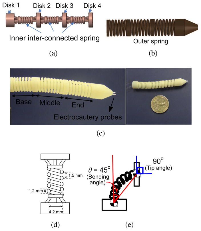
The robot is designed to have the workspace to cover deep brain tumors which have average diameter of less than 40 mm [19] and each segment should achieve a bending angle of at least 45°. It is important to note that the bending angle is relative to the orientation (surface normal vector) of the prior disk. Hence the change in bending angle causes twice the change in the surface normal of the following disk. For example, a bending angle of 45° results in a 90° orientation change of the following disk as illustrated in Fig. 1(e). Divided into three segments, the robot has a 60 mm length and a diameter of 12.6 mm. The diameter was selected to fit inside existing endoports (11–13 mm) used in microsurgical resection of deep-seated brain tumor [20], [21]. The lumen through the center of the robot has to be at least 3 mm to have enough room for electrocautery wires, and suction and irrigation tubes. The electrocautery probes are embedded at the tip of the end segment of the robot. Based on the speeds of a few existing neurosurgical robots such as the NeuroArm [22] and the ROBOCAST system [23], [24], our robot is targeted to move at 1 mm/s. There is not a required target end effector force to navigate in a brain tumor or human brain tissue (human brain tissue has a stiffness of 0.1–3 kPa [25]) since it depends on variables such as the shape and size of the tool tip, the navigation velocity, and the robot configuration. The robot motion experiment in gelatin would serve as preliminary verification of the motion capability of the robot inside the brain.
Fig. 1.
(a) CAD illustration of the inner spring (b) CAD illustration of the outer spring (c) Actual picture of the MINIR-II equipped with cautery probes (d) Schematic of one robot segment with dimensions (e) Schematic showing the surface normal of the segment disk has an orientation change (i.e. 90°) that is twice the bending angle (i.e. 45°)
Our continuum robot has a snake-like body made of four disks (Disk 1, Disk 2, Disk 3, and Disk 4) supported by interconnected inner plastic springs. It has three segments (base, middle, and end segments), maintained in a cylindrical shape by a long continuous outer spring, as shown in Fig. 1. This spring structure provides the robot with a flexible and compliant main body that allows smooth maneuverability in a soft tissue environment. At the same time it improves robot dexterity by allowing two degrees of freedom (DoFs) at a single point (like a universal joint) using two pairs of tendons terminated at four locations on each segment disc spaced 90° apart. The two antagonistic pairs of tendons enable back and forth motion of a robot segment in two independent DoFs (pitch and yaw). We explored different materials and dimensions for the springs to achieve the desired stiffness, defined by its ability to maintain its elasticity after being bent by at least 45° using SMA spring actuators without breaking. We excluded all metallic material to avoid noise in MRI images (even MRI-compatible metals can create distortion in the MRI images if placed in the imaging plane) and ended up choosing VeroWhite, a material used in the rapid prototyping machine (Objet 350V, Stratasys, USA) that has a stiffness of 2495 MPa and a 20% elongation at break. For higher spring constant and thus a higher stiffness, a large spring wire diameter was used. The outer spring, which is parallel to the inner spring, contributes slightly to the spring constant. It is primarily intended to prevent contact between the tendons and the environment and to preserve the curved shape of the robot during its motion. The selection of the plastic spring pitch, wire diameter, and spring coil diameter was done after several trials, given the spatial limitations due to the maximum allowable robot diameter and the minimum lumen diameter. The combination of 1.5 mm pitch, 1.2 mm spring wire diameter, and 4.2 mm spring coil diameter, as shown in Fig. 1(d), led to a robot segment that has flexural rigidity of 3.7 × 10⁻⁵ Nm2 and axial stiffness of 46.6 N/m. The complete three-segmented robot has flexural rigidity of 1.9 × 10⁻⁴ Nm2.
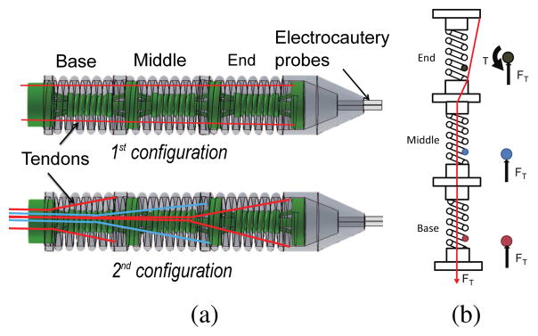
In most of the existing continuum robots with tendon driven mechanism [26], [27], tendons/alternate force transmission mechanisms are routed along the periphery of the robot, as seen in the 1st configuration in Fig. 2(a). Motion coupling between segments in a continuum robot has also been traditionally resolved by simultaneous use of multiple actuators and an appropriate control model [28]. However, we attempt to handle the problem in the design stage so as to minimize the number of actuators that need to be activated for a desired robot configuration. Inspired by the central tendon routing configuration in rigid joint robot [29] and combined continuum-rigid robot [30], we applied similar design concept on our completely flexible robot that has no pulleys at the robot joints. Different from Hirose’s design [29] which had one tendon routed around a pulley at every robot joint, pulleys are not used in the main robot body in our design to keep the robot diameter small and two sets of tendons are used at each joint to provide active back and forth motion as well as 3-dimensional motion capability for each segment. As shown in the 2nd configuration, tendons for each segment are routed through the central axis of the inter-connected springs and branch out only at the base of the target segment. When tendon pulling generates moment at the end segment, it only generates normal compression at the two other proximal segments, as shown in Fig. 2(b). We can also compensate the gravitational load on the robot body by varying the stiffness of the inter-connected spring during the design stage. Due to its elastic characteristics, the robot stays in its straight home configuration when no tension is exerted. This innovative tendon routing configuration in our robot marks a unique improvement over other continuum robots in previous research [26], [27], [31].
Fig. 2.
(a) Two configurations of tendon routing mechanism (b) Schematic showing the forces exerted in the spring wire of each segment when the 2nd tendon configuration is used
Finally, we manufactured our robot in a single piece so that in a practical application, the individual segments would not be easily separated. The lack of an assembling process also saves manufacturing time and cost, as well as allows customizable robot to be more easily produced.
III. Kinematics and Jacobian
A. Relationship between tendon displacement and joint variables
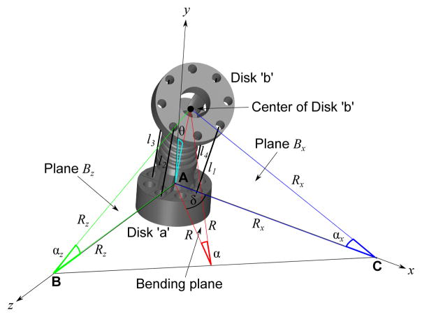
The discussion in this section focuses on a single segment, more specifically the base segment. Since the central tendon routing configuration allows independent segment motion, the kinematics framework developed here can be applied directly for the middle segment and the end segment. As discussed in Section II, since our design differs from that in [26], [27], [31], we have developed a new forward kinematic framework, based in part on the prior work of [31]. It is important to note that due to the tendons being routed along the central axis, there is a fundamental difference in the kinematics between the tendon displacement and the bending angle. Derivation of the kinematic relationship relies on the assumptions that the robot bends along a circular arc and the arc length, S, is assumed to be constant at all times due to the compliance of the inner inter-connected spring between the disks. As shown in Fig. 3, each segment has two disks: Disk ‘a’ (the stationary or proximal disk) and Disk ‘b’ (the bending or distal disk). Bending of a robot segment in any direction is a result of pulling of at most two tendons. In a general case, the robot segment would bend by bending angle θ, which is equal to α/2 or S/2R, where R is the radius of the bending arc in the bending plane, due to pulling of tendon l1 and tendon l2, as shown in Fig. 3. α is in the the bending plane which is highlighted in red. Plane Bx is the plane that intersects both the x-axis and tendon l1 whereas plane Bz is the plane that intersects both the z-axis and tendon l2.
Fig. 3.
Schematic showing geometrical relationship between the radius of the bending arc, R, and the radius of the bending arc to the x-axis, Rx and that to the z-axis, Rz. R and δ can be expressed in terms of Rx and Rz. Note that the bending angle, .
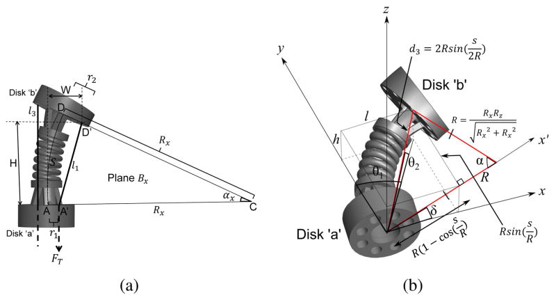
Analyzing plane Bx, as shown in Fig. 4(a), a triangle can be observed, namely ΔA′CD′. r1 and r2 are the radii of the disk from A to A′ and D to D′, respectively. Given l1, r1, r2, and S, we can determine the radius of the arc, Rx by forming a geometrical relationship between the aforementioned parameters through the law of cosines:
| (1) |
and solve it through numerical computation. l1 can be replaced by l3 for the opposite bending motion in plane Bx. Similarly, in plane Bz, Rz can be determined from the following relationship:
| (2) |
and l2 can be replaced by l4 for the opposite bending motion in plane Bz.
Fig. 4.
(a) Schematic showing relationship between the tendon length, l1 and radius of bending arc to the x-axis, Rx (b) Geometric relationship between R and δ, and the joint variables used in the kinematics model, θ1, θ2, and d3
For 3-dimensional bending motion involving both Rx and Rz as shown in Fig. 3, the radius of the bending arc, R, and the angle, δ, of the bending plane to the horizontal plane can be calculated by making use of the area of ΔABC and therefore can be expressed as: and .
R and δ are used to relate to the joint variables, θ1, θ2, and d3, as shown in Fig. 4(b). θ1 is the joint angle with the axis of rotation along the z-axis; θ2 is the joint angle with the axis of rotation along the x-axis; d3 is the displacement between the centers of Disk ‘a’ and Disk ‘b’. The position coordinate of Disk ‘b’ in the bending plane (highlighted with a red outline in Fig. 4(b)), can be expressed as:
| (3) |
As shown in Fig. 4(b), l and h can then be expressed as:
| (4) |
The joint variables for forward kinematics can be calculated as follows:
| (5) |
| (6) |
| (7) |
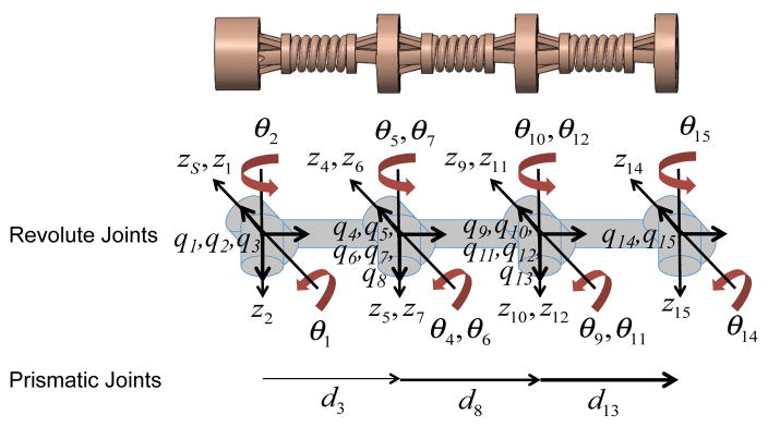
In our kinematics model, each robot segment consists of five joints, θ1, θ2, θ3 = d3, θ4, and θ5. Since the rigid body kinematics model does not account for continuous bending behavior of a flexible robot segment, θ4 and θ5 are the two virtual joints added to correct the orientation of Disk ‘b’ of each segment [31] and are related to θ1 and θ2 due to the characteristic of the continuum robot such that θ4 = θ1 and θ5 = θ2. All joint variables are clearly defined in Fig. 5.
Fig. 5.
Schematic of MINIR-II with all joints and coordinate axes defined (Subscript ‘S’ represents the base frame which coincides with the first frame.)
B. Derivation of forward kinematics using the Twist Method
As mentioned earlier, each robot segment has five joints: two orthogonal revolute joints with intersecting axes at Disk ‘a’, a prismatic joint that connects Disk ‘a’ and Disk ‘b’, and two other orthogonal revolute joints with intersecting axes at Disk ‘b’. To solve the forward kinematics for the base segment using twist coordinates, we need to obtain the product of the exponential mapping of the twists for all the joints in the segment, as expressed below:
| (8) |
where gst (0) is the initial position and orientation of Disk ‘b’ of the base segment. The exponential mapping function for revolute joints is expressed as Eq. (9).
| (9) |
where ŵ is skew symmetric matrix of the angular velocity vector and θ is the joint variable. vi is the linear velocity of each joint i. The exponential mapping function for prismatic joint is expressed as Eq. (10).
| (10) |
We first determine the angular velocity, w and link length, q for each joint with respect to the frame of the 1st joint, as seen in Eq. (11) and (12).
| (11) |
Since d3 in Fig. 5 has to be obtained from Eq. (7), it is treated as zero during derivation of the forward kinematics. This results in the following q matrix.
| (12) |
Linear velocity, vi, is the vector cross product of the wi and qi, where i = 1…5. Therefore, the twist for the base segment can be written as follows:
| (13) |
The exponential mapping of w for revolute joints i with its rotation axis along the z-axis and x-axis are respectively expressed as:
| (14) |
where Ci and Si refer to cosine of θi and sine of θi. The exponential mapping of w for the prismatic joint is a 3×3 identity matrix. Substituting angular velocity, linear velocity, and Eq. (14) into Eqs. (9) and (10), we obtain the expression for the exponential mapping of twists for revolute and prismate joints, respectively. The position and orientation matrix relative to the frame of the 1st joint, gst (0) can be expressed as:
| (15) |
Substituting Eqs. (9), (10), and (15) into Eq. (8), we obtain the final position and orientation matrix of Disk ‘b’ of the base segment, which is a 4×4 homogeneous transformation matrix, all entries of which are listed in Eq. (16).
| (16) |
The model can easily be expanded for the complete three-segmented robot to obtain the position and orientation of the true end effector (Disk ‘b’ of the end segment or Disk 4, as shown in Fig. 1(a)).
C. Jacobian
We can derive Jacobian in the spatial coordinates from the exponential mapping of the twists prime, ξ′ such that , where , which is obtained from Eq. (13). The rest of the twist primes are expressed as , where i = 2,3, … 15.
For prismatic joints (i = 3, 8, 13), , where θ’s are the joint angles while . For revolute joints, , where
| (17) |
where i = 2,4,5,6,7,9,10,11,12,14, and 15. Again, θ’s are the revolute joint angles. eŵjθj can be derived using Eq. (14). Angular velocity, w is defined with respect to the frame of the 1st joint. q for the entire three-segmented robot are listed as follows:
| (18) |
| (19) |
| (20) |
Jacobian for one robot segment can be written as:
| (21) |
Since θ4=θ1 and θ5=θ2, there are really only three independent virtual joints in one segment. The joint parameter vector can thus be defined as and the joint parameter velocity would be . Velocity vector at the task space can be related to the joint parameter velocities , where the Jacobian matrix is formed by combining the 1st and 4th columns and combining the 2nd and 5th columns in Eq. (21).
| (22) |
D. Forward Kinematics: Simulation and Experiments
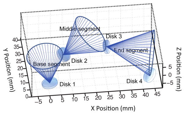
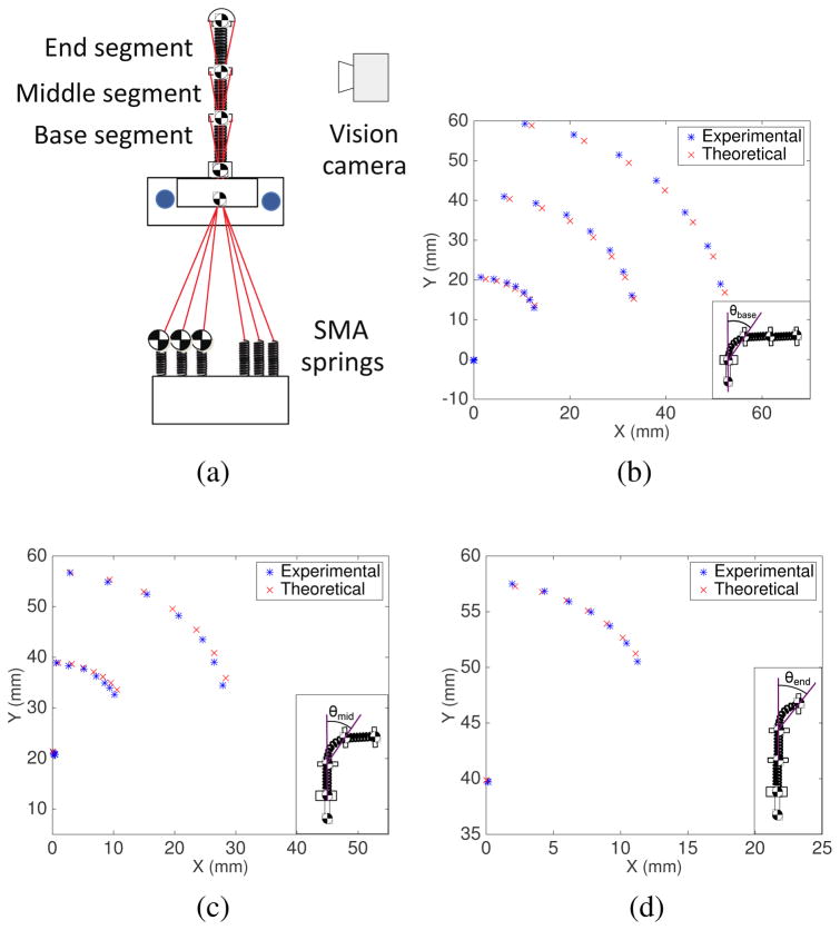
We performed MATLAB simulations of the motion of the MINIR-II robot comprised of three segments. Fig. 6 shows the simulation results of the three segments when bending angles, θ’s, of the base, middle, and end segments are equal to π/4, π/4 and π/4, and the bending plane rotates about the y-axis of the individual segment in intervals of π/20 for forty different δ angles. Each blue line indicates attachment between the positions of Disk 1, Disk 2, Disk 3, and Disk 4. We also performed verification experiment of our forward kinematics model. We used antagonistic SMA springs as actuators and the individual tendon was connected to each SMA spring assembly as shown schematically in Fig. 7(a). A marker was attached to the end of each SMA spring to measure the change in the tendon length. Four markers were attached to the discs of the robot segments to form three vectors for the three segments. They were constantly being tracked by a stereo camera that has a 15 fps resolution. The bending angle of a robot segment is defined as the relative angle of a vector formed by a robot segment with respect to the vector formed by its proximal segment. A Proportional-Integral (PI) controller monitored the difference between the real-time SMA spring displacement and the desired tendon (or SMA spring) displacement, and determined the voltage to be supplied to the SMA spring. The pulse-width modulation (PWM) signal from the Arduino board was calculated based on the voltage input (PWM signal (0–255) = voltage input/5 V) and used to heat the SMA spring. Seven tendon displacement from 1 mm to 7 mm with 1 mm interval were tested for the bending of each segment. We compared the simulation results from the kinematics model with the experimental results. Figs. 7(b), 7(c) and 7(d) show the positions of Disk ‘a’ and Disk ‘b’ of the robot segment being actuated as well as Disk ‘b’ of other segments distal to it given seven different tendon displacements. The predicted positions of the robot segments reasonably match the experimental data. The positions of Disk ‘b’ of the actuated segment, be it base, middle or end, are very well matched by the model. There are however noticeably more discrepancies in the position of the segments that are farther away from the actuated segment. This error could be due to the bending motion that was not perfectly parallel to the camera. The assumptions of constant spring length and constant spring curvature would also have contributed to modeling errors, especially at larger bending angles. To minimize the error caused by potential compression of the springs, we designed spring segments to have minimal gaps between the coils. An MRI-compatible passive magnetic field sensor will be integrated in the robot to provide position and orientation feedback to compensate for the predicted error in the real application.
Fig. 6.
Simulation result (θbase = 45°,θmid = 45°,θend = 45°)
Fig. 7.
(a) Experimental setup of forward kinematics verification (b) Position of the base, middle and end segments when the tendon connected to the base segment was pulled in 1 mm increment until 7 mm (c) Position of the base, middle and end segment when the tendon connected to the middle segment was pulled in 1 mm increment until 7 mm (d) Position of the middle and end segment when the tendon connected to the end segment was pulled in 1 mm increment until 7 mm
IV. Independent Segment Control
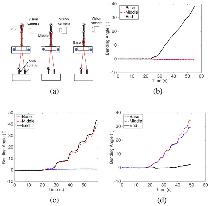
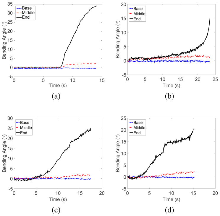
Our novel central tendon routing configuration provides better control over the motion of each robot segment than the peripheral tendon routing configuration in continuum robots [26], [27]. To verify independent segment control, we utilized the three-segment robot as shown in Fig. 8(a). Vision markers were attached to the disks of all segments. We tracked the position of each marker while a tendon was being pulled to actuate a single segment. Figures. 8(b), 8(c), and 8(d) show the bending angles of all segments during actuation of the end, middle and base segments, respectively. The results show that minimal angle changes were observed in the segments proximal to the actuated segment. When the end segment was moved, as shown in Fig. 8(b), the maximum absolute angle changes for the base and middle segments were 0.16°, and 0.48°, respectively. When the middle segment was bent, as shown in Fig. 8(c), the maximum absolute angle change for the base segment was 1.1°. Due to the characteristics of continuum robots, the segment actuated and its neighboring distal segment have almost identical bending angles, as shown in Figs. 8(c) and 8(d). We also moved the end robot segment in the yz-plane after the middle segment was moved and held fixed in the xy-plane at 0° (home configuration), 10°, 20°, and 30° (which correspond to 0°, 20°, 40°, and 60° change in the segment disk orientation-representative motion in Fig. 1(e)). As seen in Fig. 9, the maximum angle changes for the non-actuated robot segments are minimal and less than 2.1° in all cases. The slight motion in the non-actuated segments was due to friction/stiction in the overall actuation mechanism.
Fig. 8.
(a) Experimental setup schematic to determine independent segment motion by actuating only one segment; Results from the independent segment control experiments for (b) end segment, (c) middle segment and (d) base segment
Fig. 9.
Bending motion of all segments when the end segment was actuated in the z-direction after the middle segment was moved independently for (a) 0° (b) 10° (c) 20° and (d) 30° in the xy-plane
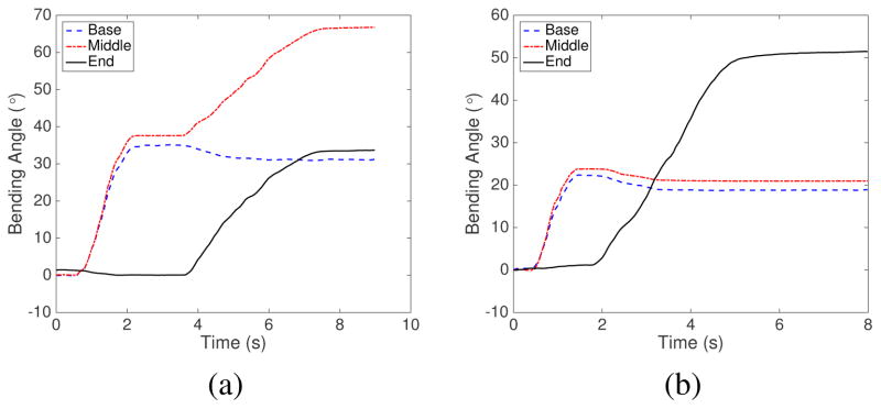
We also performed experiments for bending motion of multiple segments in the same plane: (1) bending of the base segment followed by the middle segment and (2) bending of the base segment followed by the end segment. From the results shown in Fig. 10(a), the bending of the middle segment caused a slight drop in the bending angle of the base segment which was already in a bent position in the same plane. The small drop with a maximum of 4° happened only at the beginning stage of the actuation of the middle segment and would not increase further. It was caused by the compression of the base segment spring backbone as the tendon for the middle segment was pulled to actuate the middle segment. Fig. 10(b) shows the same trend with the already bent proximal segments (base and middle) both experiencing slight drop in their bending angles as the end segment was actuated. However, for the most parts, each segment can be independently actuated even when its proximal segment is already in a bent configuration, which would not be possible using the common peripheral tendon routing configuration.
Fig. 10.
Bending motion of the base, middle, and end segments (a) when the base segment was moved independently, followed by independent actuation of the middle segment (b) when the base segment was moved independently, followed by independent actuation of the end segment
Fundamentally our design allows independent motion of each segment covering an even larger bending angles than demonstrated above. However, due to the 3-D printing plastic material, bending angles significantly beyond 45° are yet to be investigated and beyond the scope of our requirement. As the angle increases beyond 45°, we can expect more coupling due to geometrical non-linearity and possibly friction from lack of sheath around the tendons. The slight coupling between robot segments currently being displayed can be compensated through a control mechanism that introduces more tension into the proximal segments. A thin sheath can be added to each tendon to minimize the contact friction among them.
V. Force analysis
Neglecting gravitational influence, the elastic potential energy of a single robot segment due to pure bending can be expressed as [32], [33]: , where β is the flexural rigidity of a spring (a robot segment). θ, which is S/2R, is the bending angle and can be expressed in terms of θ1 and θ2 by solving Eqs. (7) and (8). When bending in a single plane, the xy-plane, θ is replaced by θ1. [34], where S, E, I, G, R, and n are the spring length, the Young’s modulus, area moment of inertia, shear modulus, mean radius of the spring coil, and number of spring coil, respectively. E = 300×106 Pa; I = 1.02×10⁻¹³ m4; ; ν = 0.3; R = 2.1 × 10⁻³ m; n = 5.
In the current work, we assumed the middle and base segments of the robot would be constrained during the electrocautery process and only the end segment would be actuated. Therefore, the relationship between the actuator torque on the three independent virtual joints in a single segment, τ and the tip force perpendicular to the d3 vector, Fk are related by τ =JTFk+∇Ee [32], [33], where J is the Jacobian for a single segment from Eq. (22) and ∇Ee is the gradient of the elastic energy with respect to the joint parameters, θ1, θ2 and d3.
For bending in xy-plane, τ can be written as follows:
| (23) |
where τ1, τ2, and τ3 are the torques provided by the three virtual joints in our forward kinematics model. F and M are the force and moment at the end disc of the single segment. To verify the model, a blocked test was performed to measure the tip force of a single segment when tension was supplied by the actuator of the first joint and the robot was in its home configuration. Therefore, Eq. (23) can be reduced to the following:
| (24) |
The angle that the tendon forms with respect to the vertical y-axis (long axis of the robot) is approximated to be the same as θ1. Therefore, FTx and FTy are calculated as FT sinθ1 and FT cosθ1, respectively. H and W can be observed in Fig. 4(a).
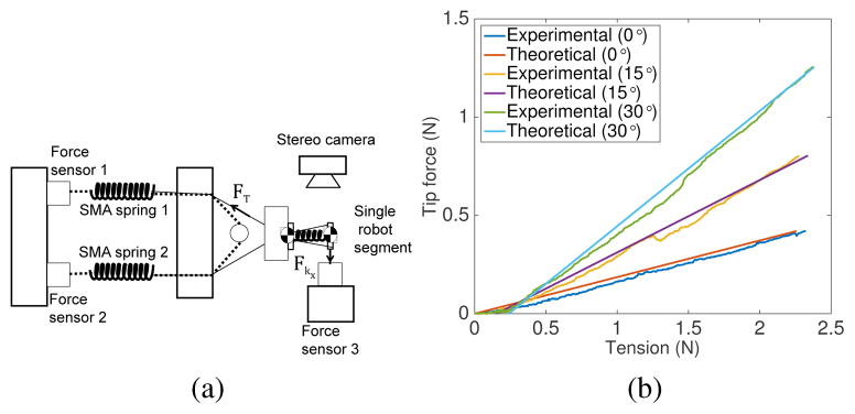
To experimentally determine the relationship between tension in the tendon and tip force, we performed blocked test with a single segment of the robot for three different bending angles, θ1’s, namely 0°, 15° and 30° (see Fig. 11(a)). A pair of SMA spring actuators were connected to the robot segment. SMA spring 1 was heated to generate the pullling force while SMA spring 2 acted as a passive spring. The tendon connecting SMA spring 2 and the robot segment was completely slack. During the experiments, forces were recorded by the three forces sensors shown in Fig. 11(a). The segment disk was attached to force sensor 3 via a solid wire to form a rigid connection and ensure good force transmission. Tension, FT can be calculated as the difference between forces recorded by force sensor 1 and force sensor 2 while tip force, Fkx was directly measured by force sensor 3.
Fig. 11.
(a) Experimental setup schematic to determine relationship between tension and tip force; (b) Experimental results
The relationship between tension and tip force is plotted in Fig. 11(b). It can be observed that the tip force exerted was 0.19 times, 0.37 times, and 0.59 times the tension applied in the tendon when θ1s were 0°, 15° and 30°, respectively. The theoretical data from Eqs. (24) matched the experimental data well (R2=0.9890, 0.9653 and 0.9934).
VI. Vision-based control with cooling strategy
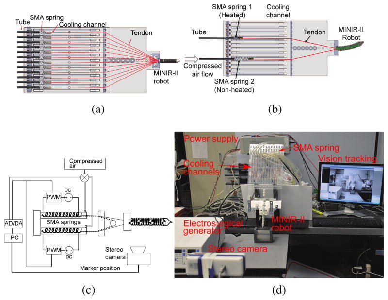
We developed a compact actuator setup and implemented the forced air cooling strategy, as seen in Fig. 12(a). To resolve the problem of slow response of the SMA springs, we used compressed air at 50 psi to cool the SMA spring actuators by blowing it into each cooling channel that has a width and height of 12 mm each. The length of the channel is 30 cm, which is more than the maximum length that the SMA spring would be extended to. Our goals are to increase the SMA cooling speed and to make the cooling mechanism as compact as possible. Higher cooling speed leads to increased actuation bandwidth and a compact cooling mechanism allows control over individual SMA spring actuators, leading to a more practical robotic setup for brain surgery. The cooling unit, as shown in Fig. 12(a), consists of acrylic plates with channels where SMA springs are located. The air tubes are connected to the channels through the holes drilled on one side of the plate. Compressed air is passed into the channels through the tubes and allowed to leave from the far end of each air channel. Figs. 12(b) and 12(c) show schematically the actuation mechanism employed in our system. As the compressed air is supplied to the non-heated SMA springs, the antagonistic SMA spring gets heated and contracts, bending the robot to one direction.
Fig. 12.
(a) CAD model of overall system consisting of the robot, six pairs of SMA springs, and their corresponding cooling channels; (b) CAD models showing air flow direction during left bending motion; (c) Schematic of resistive heating and forced air cooling strategy for single pair of antagonistic SMA springs that relates to one-DoF robot motion; (d) Complete experimental setup for vision control of MINIR-II
To ensure MRI compatibility, all components of the robot are made of plastic, except the electrocautery probes and SMA springs. The SMA springs are placed approximately 20 cm away from the robot part that is to be inserted into the brain. Thus, the actuators do not enter the brain and are away from the imaging region of the MRI scanner, avoiding heat damage to the brain tissue and distortion in MRI images. The entire continuum robotic system is composed of the robot, SMA spring actuators, the driving circuit, the cooling units, the automatic valves, a stereo camera, an electrosurgical generator (Aaron 2250, Bovie Medical Corporation, USA), and a computer with an analog-to-digital-converter (ADC) board and an Arduino board, as shown in Fig. 12(d). Vision feedback was used to control the motion of the robot. Vision markers were attached to each disk and tracked by the stereo camera to calculate vectors between the disks. A PI controller was used to calculate control signal until the desired angle was achieved. The signal indicates the time whether to heat the SMA springs or to open the valves to flow the compressed air to cool them. The Arduino board was utilized to generate PWM signals to heat the SMA actuators.
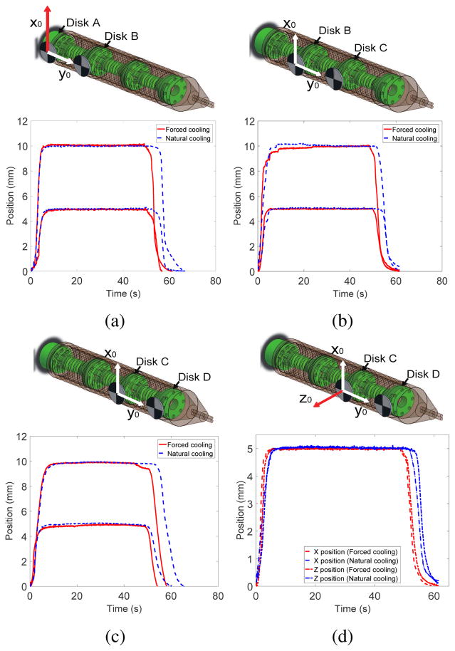
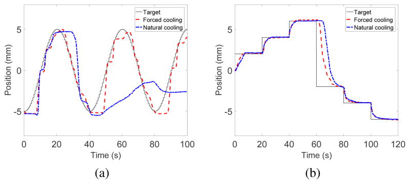
In the vision control experiment, we compared the robot tracking performance under natural cooling and forced air cooling. The experiment was repeated to demonstrate 1-DoF motion of each robot segment as well as simultaneous 2-DoF motion of the end segment. For the 1-DoF experiments, we provided 5 mm and 10 mm step inputs in the x-direction. For the 2-DoF experiment, 5 mm step inputs in both x- and z-directions were used. For sinusoidal input experiment, a wave of 5 mm amplitude with 40 s period was assigned to the middle segment of the robot. We also tested continuous motion of the middle segment at different amplitudes with 20 s time interval.
Figs. 13(a), 13(b) and 13(c) show the x position changes of Disk 2 (base segment), Disk 3 (middle segment) and Disk 4 (end segment), respectively, when desired inputs of 5 mm and 10 mm were provided under natural cooling and forced cooling. Fig. 13(d) shows the 2-DoF motion of Disk 4 when desired inputs of 5 mm in the x- and z-direction were provided simultaneously under natural cooling and forced cooling. Once the SMA springs were heated to reach the desired step input position, it took 6s and 10s to return from 5 mm position to the original configuration under forced cooling and natural cooling, respectively. It took 8s and 15s to return from 10 mm position, respectively. The slower return of the robot segment in the case of natural cooling was due to the resistance provided by the previously heated SMA spring in the antagonistic configuration, which still possessed some residual heat. The forced air cooling, on the other hand, allowed faster dissipation of residual heat in the previously heated SMA spring which therefore provided minimum resistance to its antagonistic SMA spring that was being heated. The difference in cooling time between the 5 mm and 10 mm inputs was due to the range of motion over which the SMA springs contracted and relaxed. A larger range of motion requires the SMA temperature to rise much higher and therefore more time is required to cool down. Furthermore, the temperature of the SMA spring, which had just been heated, did not drop immediately after resistive heating stopped. The position of the disk did not change until the spring force of the antagonistic SMA spring, generated by heating, became larger than the force exerted by the residual heat in the previously heated SMA spring.
Fig. 13.
Step input tracking in the x-direction for: (a) base segment, (b) middle segment and (c) end segment of MINIR-II; (d) Step input tracking of end segment in x- and z-directions
Results from the sinusoidal input experiment are shown in Fig. 14(a). Forced air cooling of the SMA spring actuators led to succesful tracking of the sinusoidal trajectory (R2 =0.9144). Under natural cooling, the robot could follow reasonably well in the first period but started to fail in the second period (R2 = 0.1760). The residual heat built up in the SMA spring without forced cooling and created a strong resistive force that hindered the sinusoidal trajectory tracking. The result for the continuous step motion experiment is shown in Fig. 14(b). We stopped heating the initially heated SMA spring after 60 s. The most significant difference between the effect of cooling methods happened between 60–80s, during which the previously heated SMA spring underwent either natural cooling or forced cooling. These trajectory following experiments confirmed the beneficial effects of forced air cooling in improving the actuation bandwidth of the robot. More experiments will be performed in our future works to determine the maximum actuation bandwidth and speed that this robot actuated by SMA springs is capable of and to investigate the various parameters that could affect its actuation bandwidth.
Fig. 14.
Motion tracking of middle segment of MINIR-II in response to (a) sinusoidal input and (b) step inputs
VII. Motion test in gelatin and MRI compatibility test
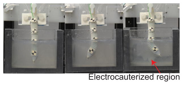
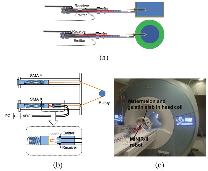
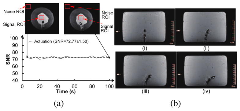
To verify motion capability of the robot in a brain-simulated environment, we inserted the robot into a gelatin (Knox, USA) slab. We then actuated the robot segment to move it back and forth while electrocauterizing the gelatin. Figure 15 shows the ability of our robot to move in a gelatin slab (2% by weight) to create electrocauterized cavities. As for the MRI-compatibility experiment, we used a gelatin slab in a cantaloupe to simulate the brain tissue in the skull. The pulp of the cantaloupe was removed and it was filled with gelatin. As shown in Fig. 16, fiber optic sensor (FU-77V, Keyence, Belgium), instead of the vision camera, was used to measure the displacement of the SMA spring during the robot motion under MRI. The entire setup was placed under a head coil at the center of an MRI scanner. Automatic valves and an air compressor are located outside the MRI room. Before actuating the robot, we took 200 high-resolution MRI images in 1000 seconds to evaluate the degree of image distortion caused by the robot and determine the signal-to-noise ratio (SNR) changes of MRI images during MRI scanning. The average SNR of the 200 images with non-actuated MINIR-II is 77.8. We then actuated the end segment of the robot and took 20 MRI images during the actuation process. The MR images and SNR changes, shown in Fig. 17(a), shows that the end segment has been moved to the left. During actuation, the average SNR of the 20 images was 72.7, which resulted in a 6.4% SNR drop. Fig. 17(b) shows the MRI images of each robot segment being bent in the gelatin.
Fig. 15.
Motion test in a gelatin slab
Fig. 16.
(a) Schematic of the MRI compatibility experiment in gelatin slab and cantaloupe (b) Detailed schematic of the laser setup to provide SMA spring displacement feedback for control (c) Actual photo of the experimental setup in the MRI room
Fig. 17.
(a) High resolution MR images of MINIR-II in a watermelon and SNR changes when the robot was actuated (b) High resolution MR images of MINIR-II in a gelatin slab: (i) Home configuration (ii) End segment bending (iii) End and middle segments bending (iv) End, middle and base segments bending
VIII. Conclusion
In this paper, we developed an MRI-compatible flexible meso-scale neurosurgical continuum robot, consisting of three segments of inter-connected spring backbone and a continuous outer spring. It offers independent segment control by routing of the tendons near the central axis of the robot. This feature has been verified through a series of experiments to test both planar and orthogonal motion between segments. The flexible robot actuated by centrally routed tendons requires a distinct kinematic model, which was derived and verified through comparison between experimental and theoretical data. We also developed the SMA cooling system using compressed air to address the concern of limited actuation bandwidth in the neurosurgical robot. Finally, we verified the MR compatibility and motion capability of the robot in gelatin. There is currently a limit on the range of motion due to degradation of the VeroGrey material which becomes brittle over time. Other material such as the Extreme Frost Detail from Shapeways was tested in the latest experiments and will be further evaluated in the future. We are also planning to add robot stiffness tuning to the current prototype to improve robot manipulation of the flexible robot. Piezomotors could eventually be used to replace the SMA actuators to improve reliability of the overall robotic system.
Acknowledgments
Research reported in this publication was supported by the National Institute Of Biomedical Imaging And Bioengineering of the National Institutes of Health under Award Number R01EB015870. The content is solely the responsibility of the authors and does not necessarily represent the official views of the National Institutes of Health.
Biographies
Dr. Yeongjin Kim is an Assistant Professor in the Department of Mechanical Engineering at Incheon National University. He received his B.S., M.S. and Ph.D. in Mechanical Engineering in 2006, 2008 and 2012, respectively, from the Korea Advance Institute of Science and Technology. He was a Research Associate in the Department of Mechanical Engineering at University of Maryland, College Park. His research interests are primarily in the area of MR-compatible surgical robotics, rehabilitation robotics, grasping, and mechanical cancer diagnosis.

Shing Shin Cheng is currently working towards his Ph.D. degree in Robotics in the Wallace H. Coulter Department of Biomedical Engineering at Georgia Institute of Technology. He earned his B.S. in Mechanical Engineering from Johns Hopkins University in 2013 and M.S. in Mechanical Engineering from the University of Maryland, College Park in 2016. His research interests include surgical robotics, smart actuators, and medical devices.

Dr. Mahamdou Diakite is a postdoc fellow at the NIH at the laboratory of imaging technology, Maryland. He received B.S in applied physics and mathematics in 2002 from university of Tunis II, Tunisia, and M.S. and Ph.D. degrees in medical physics from University of Utah in 2013. He was a postdoc fellow from 2013 to 2016 at University of Maryland Medical Center. His research interests include development of cardiac imaging pulse sequences, design and implementation of MR image reconstruction algorithms and machine learning.

Dr. Rao P. Gullapalli is Professor and Associate Vice-Chair in the Department of Diagnostic Radiology and Nuclear Medicine, and is the Director of the Core for Translational Research in Imaging at Maryland (C-TRIM) and the Center for Metabolic Imaging and Therapeutics (CMIT) at the University of Maryland School of Medicine. He holds a secondary appointment at the Fischell Department of Bioengineering at the University of Maryland College Park. His lab has been focused on the development of new imaging biomarkers associated with traumatic brain injury and to understand the utility of multi-parametric imaging for improving the sensitivity and specificity of injury detection. He is involved in the development of novel MR-guided neuro-interventions and to provide augmented realty solutions within the MRI environment. As the Director CMIT, he oversees a multi-disciplinary environment for the development of advanced metabolic imaging and development of innovative image guided interventions using focused ultrasound including treatment of essential tremors, Parkinson’s disease, and neuropathic pain.

Dr. J. Marc Simard is Professor of Neurosurgery, Pathology and Physiology at the University of Maryland School of Medicine in Baltimore. He is a board-certified clinical neurosurgeon with an active practice of neurosurgery. Dr. Simard is an experienced investigative scientist who is responsible for the original discovery of the Sur1-Trpm4 channel, and for initiating the work showing involvement of the channel in several acute CNS diseases.

Dr. Jaydev P. Desai is currently a Professor and BME Distinguished Faculty Fellow in the Wallace H. Coulter Department of Biomedical Engineering at Georgia Institute of Technology. He completed his undergraduate studies from the Indian Institute of Technology, Bombay, India, in 1993. He received his M.A. in Mathematics in 1997, M.S. and Ph.D. in Mechanical Engineering and Applied Mechanics in 1995 and 1998 respectively, all from the University of Pennsylvania. He was a Post-Doctoral Fellow in the Division of Engineering and Applied Sciences at Harvard University from 1998–1999. He is a recipient of several NIH R01 awards and NSF CAREER award. His research interests include surgical robotics, MEMS-based cancer diagnosis, micro-scale cell and tissue characterization, haptics, and grasping. He is a senior member of the IEEE and a fellow of ASME and AIMBE. He is also the Editor-in-Chief of the Journal of Medical Robotics Research.
References
- 1.Loeffler J, Patchell R, SR . Treatment of metastatic cancer. pensylvania, Philadelphia: Lippincott Raven; 1997. [Google Scholar]
- 2.Siker ML, Mehta MP. Resection versus radiosurgery for patients with brain metastases. Future Medicine. 2007 Jan;3(1):95–102. doi: 10.2217/14796694.3.1.95. [DOI] [PubMed] [Google Scholar]
- 3.Giulianotti PC, Sbrana F, Bianco FM, Elli EF, Shah G, Addeo P, Caravaglios G, Coratti A. Robot-assisted laparoscopic pancreatic surgery: single-surgeon experience. Surgical endoscopy. 2010;24(7):1646–1657. doi: 10.1007/s00464-009-0825-4. [DOI] [PubMed] [Google Scholar]
- 4.Ikuta K, Yamamoto K, Sasaki K. Development of remote microsurgery robot and new surgical procedure for deep and narrow space. Robotics and Automation, 2003. Proceedings. ICRA’03. IEEE International Conference on; IEEE; 2003. pp. 1103–1108. [Google Scholar]
- 5.Engh JA, Podnar G, Kondziolka D, Riviere CN. Toward effective needle steering in brain tissue. Engineering in Medicine and Biology Society, 2006. EMBS’06. 28th Annual International Conference of the IEEE; IEEE; 2006. pp. 559–562. [DOI] [PubMed] [Google Scholar]
- 6.Su H, Li G, Rucker DC, Webster RJ, III, Fischer GS. A concentric tube continuum robot with piezoelectric actuation for MRI-guided closed-loop targeting. Annals of biomedical engineering. 2016;44(10):2863–2873. doi: 10.1007/s10439-016-1585-7. [DOI] [PMC free article] [PubMed] [Google Scholar]
- 7.Sears P, Dupont P. A steerable needle technology using curved concentric tubes. Intelligent Robots and Systems, 2006 IEEE/RSJ International Conference on; IEEE; 2006. pp. 2850–2856. [Google Scholar]
- 8.Ho M, Kim Y, Cheng SS, Gullapalli R, Desai JP. Design, development, and evaluation of an MRI-guided SMA spring-actuated neurosurgical robot. The International Journal of Robotics Research. 2015 doi: 10.1177/0278364915579069. 0278364915579069. [DOI] [PMC free article] [PubMed] [Google Scholar]
- 9.Sheng J, Desai JP. Towards a SMA-actuated neurosurgical intracerebral hemorrhage evacuation (niche) robot. Intelligent Robots and Systems (IROS), 2015 IEEE/RSJ International Conference on; IEEE; 2015. pp. 3805–3810. [Google Scholar]
- 10.Kim D, Kobayashi E, Dohi T, Sakuma I. A new, compact MR-compatible surgical manipulator for minimally invasive liver surgery. 2002;2488:99–106. [Google Scholar]
- 11.Bo Y, U-Xuan T, McMillan AB, Gullapalli R, Desai JP. Design and control of a 1-DoF MRI-compatible pneumatically actuated robot with long transmission lines. Mechatronics, IEEE/ASME Transactions on. 2011 Dec;16(6):1040–1048. doi: 10.1109/TMECH.2010.2071393. [DOI] [PMC free article] [PubMed] [Google Scholar]
- 12.Su H, Cardona DC, Shang W, Camilo A, Cole GA, Rucker DC, Webster RJ, Fischer GS. A MRI-guided concentric tube continuum robot with piezoelectric actuation: a feasibility study. Robotics and Automation (ICRA), 2012 IEEE International Conference on; IEEE; 2012. pp. 1939–1945. [Google Scholar]
- 13.Yu N, Hollnagel C, Blickenstorfer A, Kollias S, Riener R. Comparison of MRI-compatible mechatronic systems with hydrodynamic and pneumatic actuation. Mechatronics, IEEE/ASME Transactions on. 2008 Jun;13(3):268–277. [Google Scholar]
- 14.Yang B, Tan UX, McMillan A, Gullapalli R, Desai JP. Design and control of a 1-DOF MRI-compatible pneumatically actuated robot with long transmission lines. Mechatronics, IEEE/ASME Transactions on. 2011;16(6):1040–1048. doi: 10.1109/TMECH.2010.2071393. [DOI] [PMC free article] [PubMed] [Google Scholar]
- 15.Cheng SS, Kim Y, Desai JP. Modeling and characterization of shape memory alloy springs with water cooling strategy in a neurosurgical robot. Journal of Intelligent Material Systems and Structures. 2017 doi: 10.1177/1045389X16685443. 1045389X16685443. [DOI] [PMC free article] [PubMed] [Google Scholar]
- 16.Luo SMY, Takagi T, Yamada M. A shape memory alloy actuator using peltier modules and R-Phase transition. Journal of Intelligent Material Systems and Structures. 2000;11:503. [Google Scholar]
- 17.ARR, GRB Improving the response of SMA actuators. 1995 IEEE International Conference; 1995. [Google Scholar]
- 18.Lewis AYN, Seelecke S. Experimental characterization of self-sensing SMA actuators under controlled convective cooling. Smart Materials and Structures. 2013;22 [Google Scholar]
- 19.Linzer D, Ling S, Villalobos H, Raub W, Jr, Wu X, Ting J, Berti A, Landy H, Markoe A. Gamma knife radiosurgery for large volume brain tumors: An analysis of acute and chronic toxicity. Stereotactic and functional neurosurgery. 1998;70(Suppl 1):11–18. doi: 10.1159/000056402. [DOI] [PubMed] [Google Scholar]
- 20.Ding D, Starke RM, Crowley RW, Liu KC. Endoport-assisted microsurgical resection of cerebral cavernous malformations. Journal of Clinical Neuroscience. 2015;22(6):1025–1029. doi: 10.1016/j.jocn.2015.01.004. [DOI] [PubMed] [Google Scholar]
- 21.Jo K-W, Shin HJ, Nam D-H, Lee J-I, Park K, Kim JH, Kong D-S. Efficacy of endoport-guided endoscopic resection for deepseated brain lesions. Neurosurgical review. 2011;34(4):457–463. doi: 10.1007/s10143-011-0319-4. [DOI] [PubMed] [Google Scholar]
- 22.Louw DF, Fielding T, McBeth PB, Gregoris D, Newhook P, Sutherland GR. Surgical robotics: A review and neurosurgical prototype development. Neurosurgery. 2004;54(3) doi: 10.1227/01.neu.0000108638.05274.e9. [DOI] [PubMed] [Google Scholar]
- 23.Comparetti M, De Momi E, Vaccarella A, Riechmann M, Ferrigno G. Optically tracked multi-robot system for keyhole neurosurgery. Proceedings of the IEEE International Conference on Robotics and Automation (ICRA 2011); May 2011; pp. 661–666. [Google Scholar]
- 24.De Lorenzo D, De Momi E, Dyagilev I, Manganelli R, Formaglio A, Prattichizzo D, Shoham M, Ferrigno G. Force feedback in a piezoelectric linear actuator for neurosurgery. The International Journal of Medical Robotics and Computer Assisted Surgery. 2011;7(3):268–275. doi: 10.1002/rcs.391. [DOI] [PubMed] [Google Scholar]
- 25.Murphy MC, Huston J, III, Jack CR, Jr, Glaser KJ, Senjem ML, Chen J, Manduca A, Felmlee JP, Ehman RL. Measuring the characteristic topography of brain stiffness with magnetic resonance elastography. PLoS One. 2013;8(12):e81668. doi: 10.1371/journal.pone.0081668. [DOI] [PMC free article] [PubMed] [Google Scholar]
- 26.Gravagne I, Walker I. Kinematic transformations for remotely-actuated planar continuum robots. Robotics and Automation, 2000. Proceedings. ICRA ’00. 2000;1:19–26. [Google Scholar]
- 27.Bajo A, Simaan N. Kinematics-based detection and localization of contacts along multisegment continuum robots. IEEE transsactions on robotics. 2012 Apr;28(2):291–302. [Google Scholar]
- 28.Ivanescu M, Popescu D, Popescu N. A decoupled sliding mode control for a continuum arm. Advanced Robotics. 2015;29(13):831–845. [Google Scholar]
- 29.Hirose S, Ma S. Robotics and Automation, 1991. Proceedings., 1991 IEEE International Conference on. IEEE; 1991. Coupled tendon-driven multijoint manipulator; pp. 1268–1275. [Google Scholar]
- 30.Conrad BL, Zinn MR. Intelligent Robots and Systems (IROS 2014), 2014 IEEE/RSJ International Conference on. IEEE; 2014. Interleaved continuum-rigid manipulation approach: Development and functional evaluation of a clinical scale manipulator; pp. 4290–4296. [Google Scholar]
- 31.Jones BA, Walker ID. Kinematics for multisection continuum robot. IEEE transsactions on robotics. 2006 Feb;22(1):43–57. [Google Scholar]
- 32.Fertis DG. Advanced mechanics of structures. CRC Press; 1996. [Google Scholar]
- 33.Xu K, Simaan N. An investigation of the intrinsic force sensing capabilities of continuum robots. Robotics, IEEE Transactions on. 2008;24(3):576–587. [Google Scholar]
- 34.Wahl AM. Mechanical springs. Penton Publishing Company; 1944. [Google Scholar]


