Abstract
Interbody fusion cages are routinely implanted during spinal fusion procedures to facilitate arthrodesis of a degenerated or unstable vertebral segment. Current cages are most commonly made from polyether-ether-ketone (PEEK) due to its favorable mechanical properties and imaging characteristics. However, the smooth surface of current PEEK cages may limit implant osseointegration and may inhibit successful fusion. We present the development and clinical application of the first commercially available porous PEEK fusion cage (COHERE®, Vertera, Inc., Atlanta, GA) that aims to enhance PEEK osseointegration and spinal fusion outcomes. The porous PEEK structure is extruded directly from the underlying solid and mimics the structural and mechanical properties of trabecular bone to support bone ingrowth and implant fixation. Biomechanical testing of the COHERE® device has demonstrated greater expulsion resistance versus smooth PEEK cages with ridges and greater adhesion strength of porous PEEK versus plasma-sprayed titanium coated PEEK surfaces. In vitro experiments have shown favorable cell attachment to porous PEEK and greater proliferation and mineralization of cell cultures grown on porous PEEK versus smooth PEEK and smooth titanium surfaces, suggesting that the porous structure enhances bone formation at the cellular level. At the implant level, preclinical animal studies have found comparable bone ingrowth into porous PEEK as those previously reported for porous titanium, leading to twice the fixation strength of smooth PEEK implants. Finally, two clinical case studies are presented demonstrating the effectiveness of the COHERE® device in cervical spinal fusion.
Keywords: polyether-ether-ketone, PEEK, porosity, osseointegration, spine fusion
Introduction
History of PEEK in Spine
In 2014 in the United States, spinal fusion was performed in 415,000 patients, making fusion surgery the third most common orthopaedic procedure behind hip and knee arthroplasty1,2. Spinal fusion procedures utilize neural decompression and arthrodesis to reduce pain and vertebral segment motion associated with spinal degeneration, instability, deformity and trauma3,4. First investigated in the late 1950’s, interbody spinal fusion using autograft bone, allograft bone or a synthetic interbody fusion device (IBD, or more commonly referred to as a ‘cage’) to facilitate fusion across the intervertebral disc space has now become a routine procedure5. Nevertheless, the design and composition of fusion cages continues to evolve as technologies are developed that better meet patient and surgeon needs.
The majority of current synthetic cages are made from polyether-ether-ketone (PEEK) polymer. First introduced in the 1990’s, PEEK has gained widespread acceptance in spine and orthopaedics due to its imaging characteristics, high strength, fatigue resistance and Young’s modulus that is comparable to bone to reduce stress-shielding6. Though PEEK’s mechanical and imaging properties have contributed to its popularity, recent reports have demonstrated that conventional smooth PEEK implants can exhibit poor osseointegration and fibrous encapsulation6–9. Outcomes from previous studies support that these effects result from the implant surface being smooth because both smooth PEEK and smooth titanium exhibit similarly low bone fixation compared to rough and porous surfaces10,11. However, PEEK’s poor osseointegration is often, without direct evidence, “attributed” to other properties, such as its relatively inert and hydrophobic surface chemistry10,12,13. As a result, multiple efforts to modify PEEK implants’ surface composition and improve osseointegration have been made, such as plasma-sprayed titanium coatings on PEEK (TiPEEK) and PEEK-Hydroxyapatite composites. However, many of these technologies have exhibited only modest improvements in osseointegration and may suffer practical limitations to their adoption such as potential delamination, instability, and mechanical property tradeoffs, suggesting the need to develop alternative solutions14–19.
Effects of surface structure
While PEEK’s hydrophobicity may play a role, extensive research on non-PEEK materials, particularly titanium, suggests that surface topography (or structure) would have a first-order impact on PEEK’s ability to osseointegrate. Though compositionally different, research on titanium may inform analogous investigations on PEEK, which are sparse. Surface structures on orthopaedic implants can largely be divided into two-dimensional (2D) textured surfaces and three-dimensional (3D) porous networks. Most 2D textured surfaces possess micro-scale roughness (Sa = 1–2 µm) that mimics osteoclast resorption pits and is generally associated with a beneficial bone response20,21. 2D textured surfaces possessing nano-scale features (1–100 nm) have also been investigated, though their effect on osseointegration is not as well understood21–24, and other characteristics such as surface chemistry may have a stronger effect25. In contrast to 2D surfaces, 3D surfaces are typically characterized by an interconnected porous network (100–800 µm pores) to facilitate bone ingrowth and provide mechanical interlock at the bone-implant interface26–28.
Although 2D and 3D surface structures have been shown to improve osseointegration when evaluated in isolation, recent studies have begun to investigate the combined effects of multi-scale surface features on cellular behavior and implant osseointegration. Such strategies are useful in determining the relative effects of surface features at each length scale. Notably, studies on titanium have reported that nano-scale surfaces contributed relatively little to bone cell behavior in the absence of larger micro-scale features29,30. Similarly, micro-textured surfaces appear to contribute less to implant osseointegration compared to 3D macro-porosity11,31. Taken as a whole, the titanium surface literature suggests that 3D macro-scale porosity is the dominant surface structure influencing implant osseointegration.
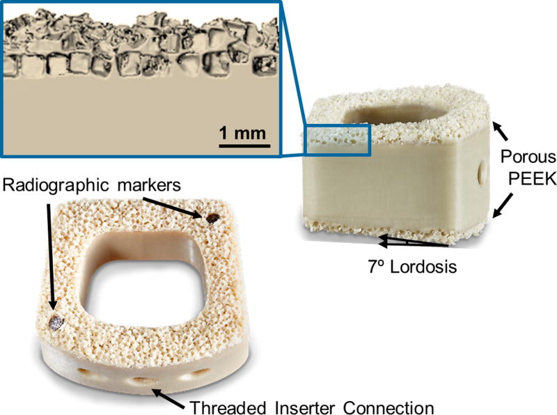
Though the above conclusions are drawn from reports on titanium, we hypothesize that similar concepts hold true for PEEK. Initial reports of bone ingrowth into porous PEEK implants supported this view, yet, until now, porous PEEK technologies in the literature had yet to reach clinical use and remained at various stages of development (Table 1)13,32–39. Herein, we describe a new porous PEEK biomaterial with similar physical and mechanical properties of standard PEEK that is able to osseointegrate without the typical fibrous tissue response associated with current smooth PEEK implants. We then demonstrate its application on a novel interbody fusion device and successful clinical use in anterior cervical discectomy and fusion (ACDF) surgery (Figure 1).
Table 1.
Development Stages of Porous PEEK in the Literature
| Source | Structural Characterization | Mechanical Testing | Cell Response | Animal Models | FDA Clearance | In Clinical Use |
|---|---|---|---|---|---|---|
| 32Edwards et al., 2012 | ● | ● | ● | |||
|
| ||||||
| 13Zhao et al., 2013 | ● | ● | ● | |||
|
| ||||||
| 33Landy et al., 2013 | ● | ● | ● | |||
|
| ||||||
| 34Evans et al., 2015 | ● | ● | ● | ● | ● | ● |
| 35Torstrick et al., 2016 | ||||||
| 36Evans et al., 2016 | ||||||
| 37Evans et al., 2017 | ||||||
|
| ||||||
| 38Siddiq et al., 2015 | ● | ● | ||||
|
| ||||||
| 39Roskies et al., 2016 | ● | ● | ||||
The Web of Science database was searched for “TITLE: ((porous OR scaffold OR three-dimensional OR 3D) AND (PEEK OR polyether ether ketone OR polyether-ether-ketone OR polyetheretherketone))” with no date restrictions on November 6, 2016. 40 results were found. 34 results were excluded based on: non-medical focus; theoretical models; porous PEEK composites; non-PEEK materials; and non-porous materials. 3 articles were added from the authors’ library.
Figure 1.
Design and features of the COHERE® implant with porous PEEK on the superior and inferior faces. The inset shows a magnified µCT reconstruction of the porous PEEK three-dimensional structure. Scale bar is 1 mm.
Porous PEEK Development
Structural and Mechanical Properties
Designed to mimic the three-dimensional structure of human trabecular bone, the porous PEEK biomaterial was created using a proprietary process that extrudes the porous architecture directly from the underlying bulk PEEK material34. Micro-computed tomography (µCT) analysis has demonstrated porous PEEK to have an average strut spacing of 169 – 248 µm, strut thickness of 73 – 119 µm, and porosity of 67 – 75%34–37 (Table 2). Corresponding µCT analysis of human trabecular bone has reported similar microstructural properties as those possessed by porous PEEK42 (Table 2).
Table 2.
Microstructural Comparison of Human Bone and Porous PEEK
| Porosity (%) | Pore Size / Strut Spacing (µm) |
Strut Thickness (µm) |
Young’s Modulus (GPa)* |
Yield Strength (MPa)* |
|
|---|---|---|---|---|---|
| Human Cortical Bone26,40 | 3 – 12 | - | - | 11.5 – 17.0 | 51 – 133 |
| Solid PEEK34 | - | - | - | 3.4 | 98 |
| Human Trabecular Bone41,42 | 74 – 92 | 638 – 854 | 122 – 194 | 0.3 – 3.2 | 2 – 17 |
| Porous PEEK34,35,37 | 67 – 75 | 169 – 248 | 73 – 119 | 0.1 | 8 – 11 |
Young’s modulus and yield strength values are reported for compressive loading.
Due to the complex loading environment within the spine, it is imperative that the porous PEEK maintains its structural integrity under physiological forces. Prior research has investigated porous PEEK’s ability to tolerate vertebral compressive loads without failure37. When isolated, the porous PEEK structure exhibited a compressive yield strength of 8 – 11 MPa and compressive modulus of 90 – 110 MPa, both ranges being of similar magnitude to vertebral trabecular bone properties26,41. For a clinical comparison, typical loading in the lumbar spine ranges from 1000 – 3000 N43,44. Thus, approximately 115 – 350 mm2 of load bearing cage area would be required to keep the porous PEEK architecture below its compressive yield strength. Detailed microstructural and mechanical properties of bone and porous PEEK are summarized in Table 226,34–37,40,41,42.
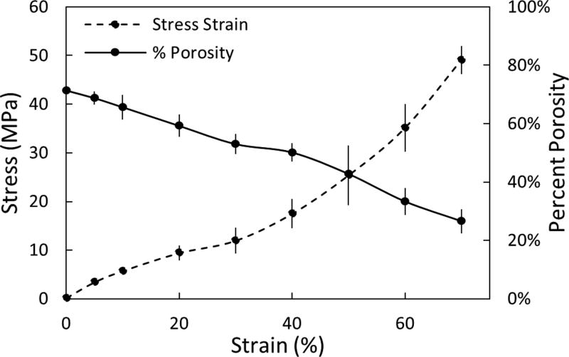
To evaluate the pore deformation that could result in cases of extreme compressive loading in the spine, porous samples were imaged at increasing strain levels (5 – 70%) using a compression device combined with µCT imaging (n=3, Scanco Medical, µCT50)37. As expected, percent porosity decreased with increasing strain. However, even at supraphysiological compressive stresses upwards of 15 – 20 MPa, the porous architecture maintained ~70% of its initial porosity that would be available for bone ingrowth (Figure 2)37.
Figure 2.
Microstructural response of porous PEEK to compression. Plot of percent porosity versus strain (solid line) with the stress-strain plot included for comparison (dashed line). Mean ± SE. (Adapted from Evans, 201737 with permission from Elsevier.)
Besides its compressive properties, porous PEEK has also been evaluated under shear fatigue and compared with TiPEEK as another clinically relevant PEEK modification. Shear fatigue testing followed ASTM F1160-05 to determine fatigue life of porous PEEK compared to TiPEEK (APS Materials, Dayton, OH). Cylindrical samples (d=20mm) were adhered with epoxy and tested in shear on a MTS Satec servohydraulic test frame at 8.1 MPa at 40 Hz with R=0.18 (n=3). The test ended when the specimen failed or a runout of 107 cycles was achieved. The TiPEEK samples failed at an average of 2,622,000 cycles, while all porous PEEK samples achieved runout of greater than 10,000,000 cycles. The chosen shear fatigue stress level of 8 MPa is greater than the shear strength of trabecular bone (5 – 7 MPa)45,46, which suggests that porous PEEK can survive physiological shear loads, while the plasma-sprayed titanium coating may not be able to survive the same physiological shear loading conditions. However, clinical evidence of plasma-sprayed titanium coating failure remains anecdotal47 and has yet to be published in the peer-reviewed literature.
Biological Properties
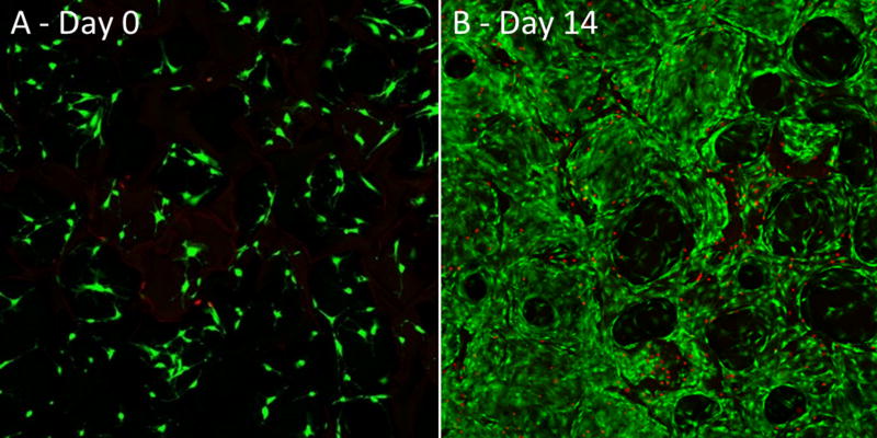
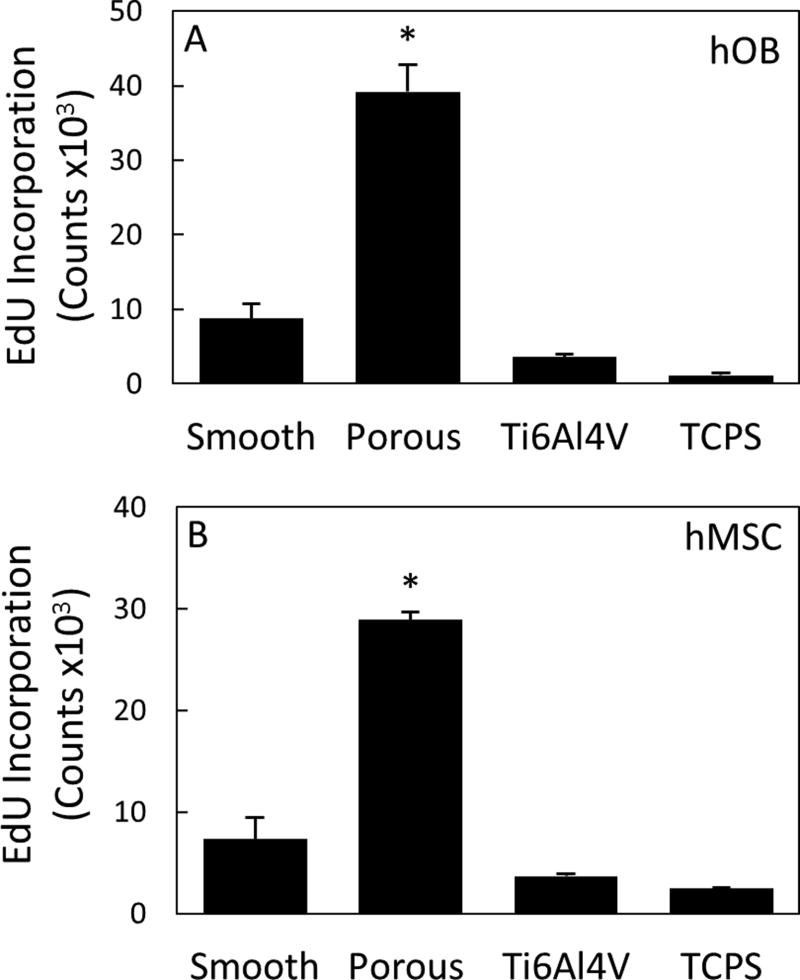
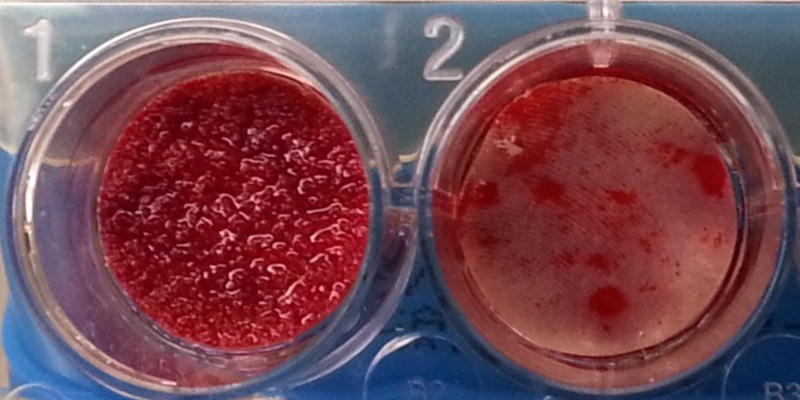
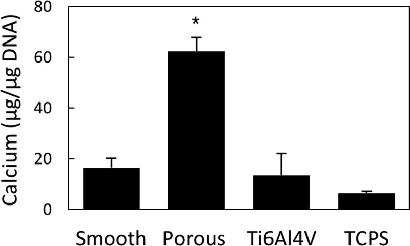
The biological performance of porous PEEK has been evaluated using a range of in vitro and in vivo models. In vitro results continue to support porous PEEK’s ability to facilitate cell attachment, proliferation and osteogenic differentiation of multiple bone cell lineages35. Live/dead imaging of clonal mouse pre-osteoblast cells (MC3T3-E1, ATCC) seeded at 20,000 cell/cm2 and cultured in growth media (α-MEM supplemented with 16.7% FBS and 1% Penicillin-Streptomycin-L-glutamine) revealed cell attachment to the porous PEEK architecture at day 0 and thorough cell layer coverage of the pores by day 14, demonstrating favorable cell growth and proliferation on porous PEEK (Figure 3). Cell proliferation on porous PEEK was further investigated by quantifying the incorporation of 5-ethynyl-2'-deoxyuridine (EdU) into the DNA of human mesenchymal stem cell (hMSC) and human osteoblast (hOB) cultures in growth media35. Both hMSC and hOB cultures exhibited increased proliferation on porous PEEK compared to smooth PEEK, smooth Ti6Al4V and tissue culture treated polystyrene (TCPS) 48 hours after seeding (Figure 4). This early proliferative phase is thought to generate extracellular matrix proteins that facilitate subsequent matrix mineralization48. Indeed, hMSC cultures exhibited extensive mineralization as evidenced by Alizarin Red staining of porous PEEK cultures grown in osteogenic media for four weeks (Figure 5). Enhanced cell-mediated mineralization of porous PEEK was further confirmed by quantifying the calcium content of in vitro cultures grown in osteogenic media for 14 days and comparing against smooth PEEK, smooth Ti6Al4V and TCPS (Figure 6). These results are consistent with previous studies on roughened and porous titanium surfaces and suggest porous PEEK can enhance mineralization at the cellular level30,49.
Figure 3.
Live/Dead confocal microscopy images of MC3T3 cultures grown on porous PEEK in growth media at (A) day 0 and (B) day 14. Live cells appear green and dead cell nuclei appear red.
Figure 4.
(A) hOB and (B) hMSC proliferation measured by DNA incorporation of EdU 48 hours after seeding on smooth PEEK, porous PEEK, Ti6Al4V, and TCPS. * p < 0.05 versus other groups (one-way ANOVA, Tukey). Mean ± SE. (Adapted from Torstrick, 201635 with permission from Springer.)
Figure 5.
Alizarin red calcium staining of hMSC cultures grown in osteogenic media for 4 weeks on porous PEEK (left) and smooth PEEK (right).
Figure 6.
MC3T3 mediated calcium deposition on porous PEEK compared with smooth PEEK, Ti6Al4V, and TCPS. * p < 0.001 versus other groups (one-way ANOVA, Tukey). Mean ± SE. (Adapted from Torstrick, 201635 with permission from Springer.)
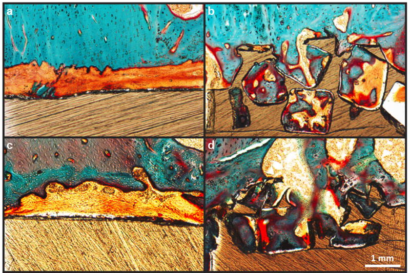
Results from pre-clinical animal models have reinforced in vitro results on porous PEEK by demonstrating its ability to support bone tissue ingrowth and implant fixation. Porous PEEK implants have undergone preliminary in vivo evaluation in a proximal tibial plug model49 (n=4–5) and femoral segmental defect (n=6) model of the rat,50, both exhibiting similar results50,51. Microcomputed tomography (µCT) imaging demonstrated that 40 ± 14% of the available pore space on tibial implants contained mineralized tissue at 8 weeks (Figure 7). This degree of bone ingrowth into porous PEEK is comparable to that previously reported for porous titanium implants52. Biomechanical pullout testing of tibial implants demonstrated that porous-faced PEEK implants exhibited over twice the integration strength of smooth PEEK implants (40.0 ± 5.4 N vs. 17.9 ± 4.6 N, p < 0.01 - Student’s t-test) (Figure 7). Non-decalcified histological sections from segmental defect samples confirmed that the mineralized tissue within the porous region was bone using a Goldner’s Trichrome stain (Figure 8). These results indicate that introducing porosity into PEEK can improve PEEK’s osseointegration.
Figure 7.
µCT images of bone growth into (A) smooth PEEK compared to (B) porous PEEK surfaces at 8 weeks. (C) Biomechanical pullout force of smooth and porous PEEK implants at 8 weeks. * p < 0.01. (Student’s t-test). Mean ± SE.
Figure 8.
Bone ingrowth of porous and smooth PEEK surfaces: (a,c) Representative histological images of fibrous tissue formation on smooth PEEK faces at six and twelve weeks, respectively. (b,d) Representative histological images of bone ingrowth within porous PEEK faces at six and twelve weeks, respectively. Osteoid stained deep red; mineralized bone stained green; fibrous tissue stained light orange; and PEEK material is seen in brown. Scale bar is 200 µm. (Reprinted from Evans, 201534 with permission from Elsevier.)
COHERE Cervical Fusion Device
Device Design
Given the mechanical and biological performance established in pre-clinical testing, a new interbody fusion device incorporating porous PEEK (COHERE®, Vertera Spine, Atlanta, GA) has been developed for use in ACDF procedures. The implant is manufactured out of a solid PEEK core with the porous PEEK architecture on the superior and inferior faces (Figure 1). This design allows for bony tissue ingrowth from adjacent vertebra while retaining the bulk physical and mechanical properties of PEEK for device structural integrity. The porous architecture also aids in creating more frictional resistance against bone, thereby reducing the risk for expulsion. Like other PEEK devices, the COHERE® device is radiolucent and does not produce imaging artifacts on X-ray and CT, a characteristic observed in the preclinical testing of porous PEEK (Figure 7). The device also features a large graft window, a 7 degree lordotic angle, and radiographic markers that run through the entire device on opposite ends.
Biomechanical Testing
The porous PEEK device has been subjected to extensive biomechanical testing to evaluate its durability and frictional properties under clinically relevant loading scenarios as part of its FDA 510(k) submission. Tensile adhesion strength testing was performed to determine the adhesive strength of the porous architecture to the solid PEEK base and compared with TiPEEK devices (Calix PC, X-Spine Systems, Inc., Miamisburg, OH). Following ASTM F1147-05, porous PEEK devices and TiPEEK devices were mounted with epoxy and pulled in tension at 0.25 cm/min with a mechanical test frame (Instron) until the components separated. Tensile adhesion strength was defined as the failure load normalized by the load-bearing cross-sectional area (n=4–5). Porous PEEK devices had a higher tensile adhesion strength than TiPEEK devices (13.7 ± 0.6 MPa vs. 7.7 ± 3.6 MPa, p < 0.01 – Student’s t-test), which supports that porous PEEK is more durable than TiPEEK. Notably these values are less than the tensile adhesion strength reported for standard flat 20 mm diameter adhesion cylinders (Porous PEEK: 24.7 ± 0.6 MPa, TiPEEK: 19.3 ± 2.1 MPa). This difference is attributed to the increased edge-to-surface ratio of these fusion devices (0.7 – 1.0 mm−1) compared to the cylindrical test samples (0.2 mm−1).
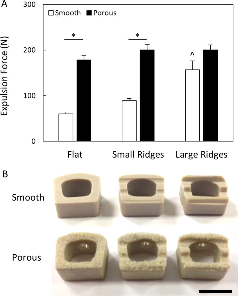
Next, porous PEEK devices were subjected to implant push-out testing in a benchtop intervertebral model to investigate their resistance to expulsion. Each device was inserted in between two polyurethane foam blocks (Sawbone, 15 PCF) and a 157 N normal force was applied to the blocks to simulate axial compression of the cervical spine. A transverse load was then applied to the posterior implant face at a rate of 0.1mm/s until the implant expulsed. Throughout the design of the COHERE® device it was determined that, in contrast to smooth devices, adding ridges to the porous faces of the implant did not improve expulsion resistance (Figure 9). Thus, COHERE® devices feature flat porous faces to provide maximum contact area between bone and porous architecture upon implantation. To ensure adequate expulsion resistance, the final COHERE® device was compared to a clinically available smooth PEEK cage that uses ridges (Crystal Cervical Interbody System, Spinal Elements, Carlsbad, CA) and the COHERE® device was found to have 71% greater expulsion force (466 ± 31 N vs. 271 ± 49 N) (p < 0.01, Student’s t-test, n=5).
Figure 9.
(A) Expulsion forces of smooth and porous PEEK devices with and without ridges. All data normalized to smooth cages without ridges. * p < 0.01, ^ p < 0.01 versus other smooth groups (two-way ANOVA, Tukey). Mean ± SE. (B) Images depicting cage and ridge geometries. Scale bar is 1 cm.
Surgical Technique
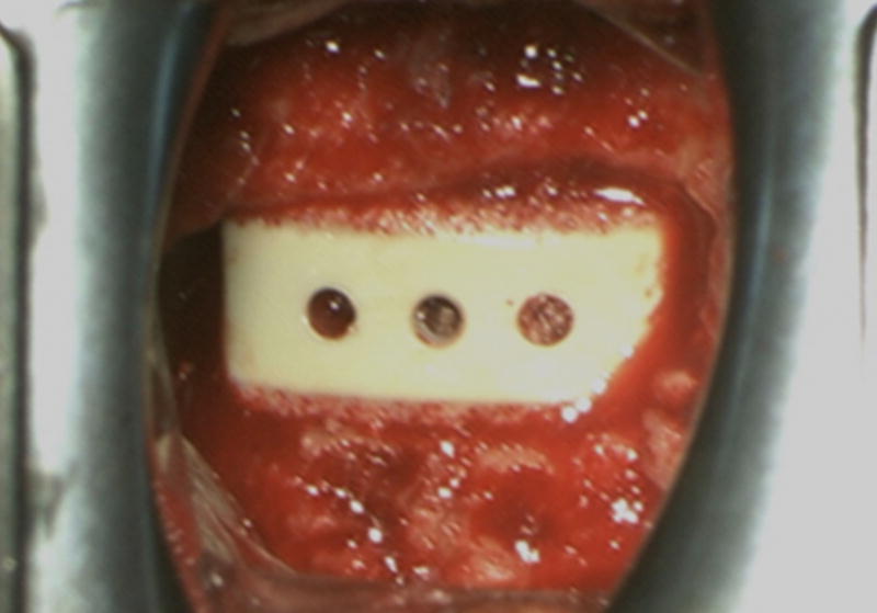
The COHERE® device can be implanted into the intervertebral disc space using a standard ACDF surgical technique similar to that used for implanting other cervical cages. The affected disc and adjacent vertebral bodies are exposed via an anterior approach. Once a discectomy is performed per standard procedure and the segment distracted, the endplates can be prepared using rasps, curettes, and/or other instruments of choice. Implant trials matching the footprint and height of each implant size offering are used to determine the appropriate COHERE® implant size. We have found the trial size (footprint×height) accurately matches the same implant footprint and height. Once the appropriate implant size is selected, the interior window of the COHERE® cage is then packed with bone graft and placed anteriorly into the disc space using a universal inserter. Of note, one of the authors has described using the high friction porous faces in a rasp-like manner to collect additional autograft from the endplates within the pores to provide an improved healing bed for fusion. Implant location can be verified on fluoroscopy as needed. If further adjustment is needed, a tamp can be used to accurately position the cage into place. Lastly, additional bone graft material can then be packed around the cage, if desired. Usually immediately following implantation, bleeding bone can be seen wicking into the porous architecture on the cage (Figure 10).
Figure 10.
Intra-operative photo showing a porous PEEK device implanted in an ACDF surgery. Soon after insertion into the disc space, blood could be seen wicking into the porous architecture.
Clinical Examples
To date, the clinical authors have performed over 100 ACDF surgeries using the COHERE® device with no device-related complications reported up to one year post-operatively. Here, two case examples are described where the COHERE® implant was used to first surgically treat a previously failed fusion surgery and then used in a multi-level surgery.
Case Example 1
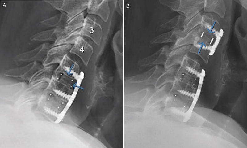
A 64-year-old female, who had undergone two previous cervical fusions in 1982 and 1997, developed adjacent segment degeneration at the C3–C4 cervical level. The patient reported neck pain and arm radiculopathy and had objective neurological signs of weakness, loss of sensation and depressed reflexes. A lateral radiograph showed disc space collapse, radial osteophyte formation, and sagittal plane malalignment (retrolisthesis and kyphosis) at the C3–C4 level (Figure 11A).
Figure 11.
(A) Pre-operative and (B) 3 month post-operative lateral radiographs of a patient who underwent ACDF surgery and received a porous PEEK implant at level C3–C4. The post-operative image showed that disc height and lordosis had been restored and maintained with evidence of bony bridging.
The patient underwent an ACDF and received a porous PEEK COHERE® implant in conjunction with an anterior plate and autogenous iliac crest taken through a minimally invasive approach using only cancellous bone and bone marrow aspirate. At 3 months after surgery, a lateral radiograph showed restoration and maintenance of anatomic disc space height, segmental lordosis, and normal sagittal alignment (Figure 11B). The patient had excellent relief of neck pain and radiating pain with complete return of neurological status. After surgery and follow-up she was neurologically intact. Importantly, there were no lucencies around the PEEK implant. An uninterrupted, continuous column of bone was seen through the central portion of the COHERE implant with complete integration of the bone graft to the bony endplates of the adjacent vertebra.
Case Example 2
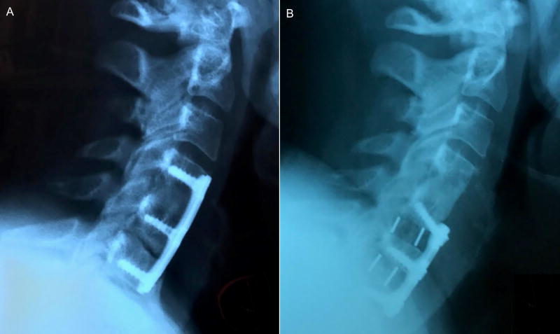
A 55-year old female patient with a history of diabetes type 2 and BMI greater than 50 presented for evaluation and management after having had a previous multi-level ACDF (C4–C6) with an outside surgeon approximately 7 years prior. The patient presented with persistent neck pain of 7/10 on the pain scale, with 100% neck pain. The patient was ordered to undergo an EMG and CT Myelogram. The EMG of the upper extremities was unremarkable. The cervical spine CT Myelogram revealed a disc osteophyte complex at C6–C7 cervical level with pseudarthrosis at C5–C6 level (Figure 12A).
Figure 12.
(A) Pre-operative and (B) 5 month post-operative lateral radiographs of patient who underwent ACDF surgery and received 2 porous PEEK implants at C5–C6 and C6–C7 levels. Post-operative image shows bony bridging across disc space.
After a year of unsuccessful conservative treatment, the patient underwent surgery for revision ACDF using the porous PEEK COHERE® implant for painful pseudoarthrosis at C5–C6 with microscopic anterior discectomy and decompression of spinal canal stenosis as well as bilateral neuroforaminotomies at C6–C7, with extension of fusion at C6–C7 (Figure 12B). Demineralized bone matrix (DBM) was used as allograft to fill the interior window of the cage along with plates and screws to provide segmental stabilization.
At 5 months following surgery, the patient was seen for follow-up. Anterior-posterior (A-P) and lateral radiographs were completed showing the COHERE® implant, plate, and screws intact and in good position with solid-appearing interosseous growth at C5–C6 and C6–C7. It was noted that disc height had improved and lordosis had been restored and maintained. The patient reported functional range of motion in all planes of the cervical spine and presented a post-operative pain score of 0/10. The patient had discontinued all opiate use four months post-operatively.
Conclusions
Preliminary clinical and preclinical results suggest that the COHERE® interbody fusion device featuring porous PEEK can support spinal fusion and may offer improved osseointegration compared to conventional smooth PEEK. The method of extruding the pores from the underlying solid imparts unique mechanical properties that support porous PEEK’s ability to bear physiological loads without crushing or delamination. Future studies are focused on evaluating long-term clinical outcomes to assess the efficacy and stability of the COHERE® device.
Acknowledgments
Conflicts of Interest and Sources of Funding:
FBT, DLS, CSDL, REG, KG and KES own stock in Vertera, Inc. JKB and JLC are consultants for Vertera, Inc. Funding for this work was provided by the Georgia Research Alliance (RG036/2506R08), National Science Foundation (2013162284) and the National Center for Advancing Translational Sciences of the National Institutes of Health (UL1TR000454).
References
- 1.Healthcare Cost and Utilization Project (HCUP) [database online] Rockville, MD: Agency for Healthcare Research and Quality; 1997–2012. [PubMed] [Google Scholar]
- 2.Rajaee SS, Bae HW, Kanim LE, et al. Spinal fusion in the United States: analysis of trends from 1998 to 2008. Spine (Phila Pa 1976) 2012;37:67–76. doi: 10.1097/BRS.0b013e31820cccfb. [DOI] [PubMed] [Google Scholar]
- 3.Deyo RA, Nachemson A, Mirza SK. Spinal-Fusion Surgery — The Case for Restraint. N. Engl. J. Med. 2004;350:722–726. doi: 10.1056/NEJMsb031771. [DOI] [PubMed] [Google Scholar]
- 4.Wang JC, Mummaneni PV, Haid RW. Current treatment strategies for the painful lumbar motion segment: posterolateral fusion versus interbody fusion. Spine (Phila Pa 1976) 2005;30:S33–43. doi: 10.1097/01.brs.0000174559.13749.83. [DOI] [PubMed] [Google Scholar]
- 5.Smith GW, Robinson RA. The Treatment of Certain Cervical-Spine Disorders by Anterior Removal of the Intervertebral Disc and Interbody Fusion. The Journal of Bone & Joint Surgery. 1958;40:607–624. [PubMed] [Google Scholar]
- 6.Kurtz SM, Devine JN. PEEK biomaterials in trauma, orthopedic, and spinal implants. Biomaterials. 2007;28:4845–4869. doi: 10.1016/j.biomaterials.2007.07.013. [DOI] [PMC free article] [PubMed] [Google Scholar]
- 7.Devine DM, Hahn J, Richards RG, et al. Coating of carbon fiber-reinforced polyetheretherketone implants with titanium to improve bone apposition. J Biomed Mater Res B Appl Biomater. 2013;101:591–598. doi: 10.1002/jbm.b.32861. [DOI] [PubMed] [Google Scholar]
- 8.Jockisch KA, Brown SA, Bauer TW, et al. Biological response to chopped-carbon-fiber-reinforced peek. J. Biomed. Mater. Res. 1992;26:133–146. doi: 10.1002/jbm.820260202. [DOI] [PubMed] [Google Scholar]
- 9.Nieminen T, Kallela I, Wuolijoki E, et al. Amorphous and crystalline polyetheretherketone: Mechanical properties and tissue reactions during a 3-year follow-up. Journal of Biomedical Materials Research Part A. 2008;84A:377–383. doi: 10.1002/jbm.a.31310. [DOI] [PubMed] [Google Scholar]
- 10.Walsh WR, Bertollo N, Christou C, et al. Plasma-sprayed titanium coating to polyetheretherketone improves the bone-implant interface. Spine J. 2015;15:1041–1049. doi: 10.1016/j.spinee.2014.12.018. [DOI] [PubMed] [Google Scholar]
- 11.Svehla M, Morberg P, Zicat B, et al. Morphometric and mechanical evaluation of titanium implant integration: comparison of five surface structures. J. Biomed. Mater. Res. 2000;51:15–22. doi: 10.1002/(sici)1097-4636(200007)51:1<15::aid-jbm3>3.0.co;2-9. [DOI] [PubMed] [Google Scholar]
- 12.Lee JH, Jang HL, Lee KM, et al. Cold-spray coating of hydroxyapatite on a three-dimensional polyetheretherketone implant and its biocompatibility evaluated by in vitro and in vivo minipig model. Journal of Biomedical Materials Research Part B: Applied Biomaterials. 2015 doi: 10.1002/jbm.b.33589. n/a-n/a. [DOI] [PubMed] [Google Scholar]
- 13.Zhao Y, Wong HM, Wang W, et al. Cytocompatibility, osseointegration, and bioactivity of three-dimensional porous and nanostructured network on polyetheretherketone. Biomaterials. 2013;34:9264–9277. doi: 10.1016/j.biomaterials.2013.08.071. [DOI] [PubMed] [Google Scholar]
- 14.Kienle A, Graf N, Wilke H-J. Does impaction of titanium-coated interbody fusion cages into the disc space cause wear debris or delamination? The Spine Journal. 2016;16:235–242. doi: 10.1016/j.spinee.2015.09.038. [DOI] [PubMed] [Google Scholar]
- 15.Abu Bakar MS, Cheng MHW, Tang SM, et al. Tensile properties, tension–tension fatigue and biological response of polyetheretherketone–hydroxyapatite composites for load-bearing orthopedic implants. Biomaterials. 2003;24:2245–2250. doi: 10.1016/s0142-9612(03)00028-0. [DOI] [PubMed] [Google Scholar]
- 16.Briem D, Strametz S, Schröoder K, et al. Response of primary fibroblasts and osteoblasts to plasma treated polyetheretherketone (PEEK) surfaces. J. Mater. Sci. Mater. Med. 2005;16:671–677. doi: 10.1007/s10856-005-2539-z. [DOI] [PubMed] [Google Scholar]
- 17.Han C-M, Lee E-J, Kim H-E, et al. The electron beam deposition of titanium on polyetheretherketone (PEEK) and the resulting enhanced biological properties. Biomaterials. 2010;31:3465–3470. doi: 10.1016/j.biomaterials.2009.12.030. [DOI] [PubMed] [Google Scholar]
- 18.Poulsson AH, Eglin D, Zeiter S, et al. Osseointegration of machined, injection moulded and oxygen plasma modified PEEK implants in a sheep model. Biomaterials. 2014;35:3717–3728. doi: 10.1016/j.biomaterials.2013.12.056. [DOI] [PubMed] [Google Scholar]
- 19.Rymuszka D, Terpilowski K, Borowski P, et al. Time Dependent Changes of Surface Properties of Polyether Ether Ketone Caused by Air Plasma Treatment. Polymer International. 2016 n/a-n/a. [Google Scholar]
- 20.Martin JY, Schwartz Z, Hummert TW, et al. Effect of titanium surface roughness on proliferation, differentiation, and protein synthesis of human osteoblast-like cells (MG63) J. Biomed. Mater. Res. 1995;29:389–401. doi: 10.1002/jbm.820290314. [DOI] [PubMed] [Google Scholar]
- 21.Wennerberg A, Albrektsson T. Effects of titanium surface topography on bone integration: a systematic review. Clin. Oral Implants Res. 2009;20(Suppl 4):172–184. doi: 10.1111/j.1600-0501.2009.01775.x. [DOI] [PubMed] [Google Scholar]
- 22.Price RL, Ellison K, Haberstroh KM, et al. Nanometer surface roughness increases select osteoblast adhesion on carbon nanofiber compacts. Journal of Biomedical Materials Research Part A. 2004;70A:129–138. doi: 10.1002/jbm.a.30073. [DOI] [PubMed] [Google Scholar]
- 23.Yang L, Sheldon BW, Webster TJ. The impact of diamond nanocrystallinity on osteoblast functions. Biomaterials. 2009;30:3458–3465. doi: 10.1016/j.biomaterials.2009.03.014. [DOI] [PubMed] [Google Scholar]
- 24.Cai K, Bossert J, Jandt KD. Does the nanometre scale topography of titanium influence protein adsorption and cell proliferation? Colloids and Surfaces B: Biointerfaces. 2006;49:136–144. doi: 10.1016/j.colsurfb.2006.02.016. [DOI] [PubMed] [Google Scholar]
- 25.Lotz EM, Olivares-Navarrete R, Berner S, et al. Osteogenic Response of Human MSCs and Osteoblasts to Hydrophilic and Hydrophobic Nanostructured Titanium Implant Surfaces. Journal of Biomedical Materials Research Part A. 2016 doi: 10.1002/jbm.a.35852. n/a-n/a. [DOI] [PubMed] [Google Scholar]
- 26.Karageorgiou V, Kaplan D. Porosity of 3D biomaterial scaffolds and osteogenesis. Biomaterials. 2005;26:5474–5491. doi: 10.1016/j.biomaterials.2005.02.002. [DOI] [PubMed] [Google Scholar]
- 27.Converse GL, Conrad TL, Roeder RK. Mechanical properties of hydroxyapatite whisker reinforced polyetherketoneketone composite scaffolds. J Mech Behav Biomed Mater. 2009;2:627–635. doi: 10.1016/j.jmbbm.2009.07.002. [DOI] [PubMed] [Google Scholar]
- 28.Lewallen EA, Riester SM, Bonin CA, et al. Biological Strategies for Improved Osseointegration and Osteoinduction of Porous Metal Orthopedic Implants. Tissue Engineering Part B: Reviews. 2014;21:218–230. doi: 10.1089/ten.teb.2014.0333. [DOI] [PMC free article] [PubMed] [Google Scholar]
- 29.Zhao G, Raines AL, Wieland M, et al. Requirement for both micron- and submicron scale structure for synergistic responses of osteoblasts to substrate surface energy and topography. Biomaterials. 2007;28:2821–2829. doi: 10.1016/j.biomaterials.2007.02.024. [DOI] [PMC free article] [PubMed] [Google Scholar]
- 30.Gittens RA, Olivares-Navarrete R, McLachlan T, et al. Differential responses of osteoblast lineage cells to nanotopographically-modified, microroughened titanium-aluminum-vanadium alloy surfaces. Biomaterials. 2012;33:8986–8994. doi: 10.1016/j.biomaterials.2012.08.059. [DOI] [PMC free article] [PubMed] [Google Scholar]
- 31.Wang X, Schwartz Z, Gittens RA, et al. Role of integrin alpha(2)beta(1) in mediating osteoblastic differentiation on three-dimensional titanium scaffolds with submicron-scale texture. Journal of Biomedical Materials Research Part A. 2015;103:1907–1918. doi: 10.1002/jbm.a.35323. [DOI] [PMC free article] [PubMed] [Google Scholar]
- 32.Edwards SL, Werkmeister JA. Mechanical evaluation and cell response of woven polyetheretherketone scaffolds. Journal of Biomedical Materials Research Part A. 2012;100A:3326–3331. doi: 10.1002/jbm.a.34286. [DOI] [PubMed] [Google Scholar]
- 33.Landy BC, Vangordon SB, McFetridge PS, et al. Mechanical and in vitro investigation of a porous PEEK foam for medical device implants. J Appl Biomater Funct Mater. 2013;11:e35–44. doi: 10.5301/JABFM.2012.9771. [DOI] [PubMed] [Google Scholar]
- 34.Evans NT, Torstrick FB, Lee CS, et al. High-strength, surface-porous polyether-ether-ketone for load-bearing orthopedic implants. Acta Biomater. 2015;13:159–167. doi: 10.1016/j.actbio.2014.11.030. [DOI] [PMC free article] [PubMed] [Google Scholar]
- 35.Torstrick FB, Evans NT, Stevens HY, et al. Do Surface Porosity and Pore Size Influence Mechanical Properties and Cellular Response to PEEK? Clin. Orthop. Relat. R. 2016;474:2373–2383. doi: 10.1007/s11999-016-4833-0. [DOI] [PMC free article] [PubMed] [Google Scholar]
- 36.Evans NT, Irvin CW, Safranski DL, et al. Impact of surface porosity and topography on the mechanical behavior of high strength biomedical polymers. J Mech Behav Biomed. 2016;59:459–473. doi: 10.1016/j.jmbbm.2016.02.033. [DOI] [PubMed] [Google Scholar]
- 37.Evans NT, Torstrick FB, Safranski DL, et al. Local deformation behavior of surface porous polyether-ether-ketone. J Mech Behav Biomed. 2017;65:522–532. doi: 10.1016/j.jmbbm.2016.09.006. [DOI] [PubMed] [Google Scholar]
- 38.Siddiq AR, Kennedy AR. Porous poly-ether ether ketone (PEEK) manufactured by a novel powder route using near-spherical salt bead porogens: Characterisation and mechanical properties. Mat Sci Eng C-Mater. 2015;47:180–188. doi: 10.1016/j.msec.2014.11.044. [DOI] [PubMed] [Google Scholar]
- 39.Roskies M, Jordan JO, Fang DD, et al. Improving PEEK bioactivity for craniofacial reconstruction using a 3D printed scaffold embedded with mesenchymal stem cells. J. Biomater. Appl. 2016;31:132–139. doi: 10.1177/0885328216638636. [DOI] [PubMed] [Google Scholar]
- 40.Cooper DML, Matyas JR, Katzenberg MA, et al. Comparison of Microcomputed Tomographic and Microradiographic Measurements of Cortical Bone Porosity. Calcif. Tissue Int. 2004;74:437–447. doi: 10.1007/s00223-003-0071-z. [DOI] [PubMed] [Google Scholar]
- 41.Morgan EF, Keaveny TM. Dependence of yield strain of human trabecular bone on anatomic site. J. Biomech. 2001;34:569–577. doi: 10.1016/s0021-9290(01)00011-2. [DOI] [PubMed] [Google Scholar]
- 42.Hildebrand T, Laib A, Muller R, et al. Direct three-dimensional morphometric analysis of human cancellous bone: microstructural data from spine, femur, iliac crest, and calcaneus. J Bone Miner Res. 1999;14:1167–1174. doi: 10.1359/jbmr.1999.14.7.1167. [DOI] [PubMed] [Google Scholar]
- 43.Schultz AB, Andersson GBJ. Analysis of Loads on the Lumbar Spine. Spine (Phila Pa 1976) 1981;6:76–82. doi: 10.1097/00007632-198101000-00017. [DOI] [PubMed] [Google Scholar]
- 44.Nachemson A. Lumbar Intradiscal Pressure: Experimental Studies on Post-Mortem Material. Acta Orthop. Scand. 1960;31:1–104. doi: 10.3109/ort.1960.31.suppl-43.01. [DOI] [PubMed] [Google Scholar]
- 45.Stone JL, Beaupre GS, Hayes WC. Multiaxial strength characteristics of trabecular bone. J. Biomech. 1983;16:743–752. doi: 10.1016/0021-9290(83)90083-0. [DOI] [PubMed] [Google Scholar]
- 46.Goldstein SA. The mechanical properties of trabecular bone: dependence on anatomic location and function. J. Biomech. 1987;20:1055–1061. doi: 10.1016/0021-9290(87)90023-6. [DOI] [PubMed] [Google Scholar]
- 47.Roybal R. 11th Annual Castellvi Spine Meeting. Duck Key, FL: 2016. [Google Scholar]
- 48.Lian JB, Stein GS. Concepts of osteoblast growth and differentiation: basis for modulation of bone cell development and tissue formation. Crit. Rev. Oral Biol. Med. 1992;3:269–305. doi: 10.1177/10454411920030030501. [DOI] [PubMed] [Google Scholar]
- 49.Alice C, Aiza H, David JC, et al. Additively manufactured 3D porous Ti-6Al-4V constructs mimic trabecular bone structure and regulate osteoblast proliferation, differentiation and local factor production in a porosity and surface roughness dependent manner. Biofabrication. 2014;6:045007. doi: 10.1088/1758-5082/6/4/045007. [DOI] [PMC free article] [PubMed] [Google Scholar]
- 50.Agarwal R, Gonzalez-Garcia C, Torstrick B, et al. Simple coating with fibronectin fragment enhances stainless steel screw osseointegration in healthy and osteoporotic rats. Biomaterials. 2015;63:137–145. doi: 10.1016/j.biomaterials.2015.06.025. [DOI] [PMC free article] [PubMed] [Google Scholar]
- 51.Oest ME, Dupont KM, Kong H-J, et al. Quantitative assessment of scaffold and growth factor-mediated repair of critically sized bone defects. J. Orthop. Res. 2007;25:941–950. doi: 10.1002/jor.20372. [DOI] [PubMed] [Google Scholar]
- 52.Clemow AJ, Weinstein AM, Klawitter JJ, et al. Interface mechanics of porous titanium implants. J. Biomed. Mater. Res. 1981;15:73–82. doi: 10.1002/jbm.820150111. [DOI] [PubMed] [Google Scholar]


