Abstract
Minimally invasive percutaneous approaches routinely employ insertion of needles into soft tissue for diagnostic or therapeutic purposes. Lack of targeting accuracy while inserting needles can significantly mitigate the effectiveness of these methods. Robot-assisted needle steering under magnetic resonance imaging (MRI) guidance is a viable option for reaching the target accurately. In this paper, we report the development of an MRI-compatible needle driver for in-bore prostate biopsy. The device easily mounts onto and works together with our previously developed MRI-compatible prostate interventional robot. It is the first robotic device using a standard biopsy gun, which is easily replaceable/detachable in case of multi-sampling biopsy applications. The mechanism enables rotation, translation, and triggering of the biopsy gun to steer the bevel needle through the tissue and to take samples accurately from the target loci. Using the rotational and translational capabilities, the same system can also assist brachytherapy needle placement. Preliminary experiments have shown that the design meets the requirements set by the clinical workflow. System feasibility was verified by multiple users inserting 2 different types of needles under visual feedback into a phantom made of soft plastic. The average targeting errors were 0.92 mm for 18 gauge biopsy and 1.65 mm for 20 gauge brachytherapy needle.
Keywords: MRI-compatibility, needle driver, prostate biopsy, bevel-tip needle steering
I. Introduction
Needle placement into soft tissue is a common task in many of the minimally invasive surgical approaches. Biopsy, brachytherapy and thermal ablation are some of the leading examples. These procedures require precise insertion of a needle into a target, inside a tumor, while avoiding critical anatomical features, such as blood vessels or nerves. The operation is usually challenged by the relative loci of the surrounding organs, target mobility, tissue deformation and varying tissue stiffness. Research on robot-assisted needle placement focuses on developing approaches that are more accurate, efficient and user-friendly.
Percutaneous needle insertion can be done through different methods. (1) A conventional approach is to use a stiff needle with symmetric tip and perform the insertion following a straight path. This is a simple way to reach the target as long as it is located in close proximity of the skin. In this case, deflection of the needle and soft-tissue deformation are not taken into account. Thus, using this method, it is not possible to avoid any obstacles between the insertion point and the target. (2) Alternatively, the surgeon can tilt or rotate the needle from outside the patient’s body deforming the tissue, and manipulating the insertion direction. This approach still uses stiff symmetric needles and was explored in [1], [2]. When the target is in a deep position though, this method requires much larger forces to be applied. Deforming the tissue by exerting large forces increases tissue damage and limits the feasibility for accurate targeting. (3) Research in recent years focused on a third approach called “needle steering”, which makes use of bevel-tip needles, and rotates the needle axially during insertion to deform the flexible needle toward the target [3], [4]. A bevel-tip needle will bend against the direction of the bevel and rotation about its axis will modify its bending direction. Based on this feature, by modulating the needle orientation during insertion, targets behind obstacles can be reached without significant tissue damage.
Several mainstream imaging techniques can provide navigation for needle steering procedures. In context of prostate cancer, there have been extensive research on ultrasound-guided surgery. Ultrasound is a low-cost “gold standard” navigation method for biopsy [5] and has no adverse radiative effect. However, the ultrasound probe and other mounting hardware can potentially prevent the needle from reaching the area behind the pubic arch, which is commonly called “pubic arch interference [6].” Computed Tomography (CT) and Magnetic Resonance Imaging (MRI) allow dose planning based on anatomy not distorted by transrectal ultrasound probes [7], which provide convenience during medical procedures. CT introduces X-ray radiation and requires surgeon to be protected during operation. MRI provides the best soft tissue contrast among the three imaging modalities and has been widely used in recent studies [8], [9]. The most significant challenge of operating in an MRI room is to use only the devices that are free of ferromagnetic materials. Compatible devices should not be influenced by the generated strong magnetic field, and should not interfere with the quality of imaging. A variety of devices were proposed for automating biopsy and brachytheraphy procedures during the last two decades [10-1214-16]. Despite the potential accuracy and operational time improvement these mechanisms could provide, a major drawback in these approaches is the use of customized end effectors rather than standard clinical needles. This requires additional approvals before the system can be tested clinically in the operating room.
Previously, a 5-degree-of-freedom (DOF), MRI compatible prostate needle placement robot system was previously developed by our group [5], [13]. This system consisted of a base robot performing 4-DOF movement by the combined motion of two pneumatically actuated bi-triangle mechanisms, and a needle driver module for inserting standard brachytherapy needles. The system’s feasibility and accuracy were analyzed in ex-vivo phantom trials. Due to control challenges associated with the pneumatic actuators and for better targeting accuracy, the base robot was further improved by replacing the pneumatic actuators with powerful nonmagnetic ultrasonic motors [14]. This version automatically adjusts the needle guide pose and requires a clinician to manually insert a standard biopsy needle along the direction guided by the robot. This approach is currently under clinical validation (Fig. 1a).
Fig. 1.
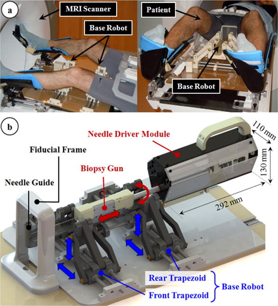
The robotic system: (a) The base robot adjusts the orientation and position of the needle guide, and is currently under clinical validation [15]. (b) The needle driver module inserts and rotates the biopsy gun through the needle guide, and triggers it for taking a tissue sample from a clinical target accurately.
This work presents an MRI-compatible needle driving device that builds onto the current version of our 4-DOF base robot, and aims toward a 7-DOF robotic platform that assists needle insertion during MRI-guided prostate biopsy and brachytherapy procedures. The devised module satisfies the material and size constraints for operating inside the MRI bore, enables (1) axial rotation, (2) translation (along the direction set by the 4-DOF base robot) and (3) triggering of the biopsy needle to steer through tissues to reach a target, and collect samples accurately. It uses a commercial biopsy gun (TSK Laboratory, Japan). This is, to the best of our knowledge, the first study to operate a standard biopsy gun in a needle steering study. The modular design of the system eliminates the need of moving the patient out of the scanner repeatedly in a multi-biopsy procedure. The functionality of the needle driver has been validated through preliminary experiments in artificial phantoms. The clinician-in-loop, step-by-step insertion strategy provides safety during operation.
In the following sections, we will first present the mechanical design and control system architecture of our device. Section III explicates the preliminary experimental evaluation of the needle driver module. This is followed by a discussion of the results, and our future aims.
II. The Robotic System
A. Mechanical Design
The principal target in this study is accurate transperineal needle placement in the prostate under MRI guidance for diagnostic (biopsy) or therapeutic (brachytherapy seed placement) purposes. During the mechanical design phase of our system, we considered the constraints of the clinical environment and workflow. In the clinical setup, the patient lies in the semilithotomy position with legs raised as in Fig. 1a. We developed a robotic system that operates in the confined space between the patient's legs and inside the MRI bore. The system consists of two main parts (Fig. 1b): the base robot and the needle driver module.
The base robot is a 4-DOF parallel manipulator and is actuated by moving the front and rear trapezoid stages. It employs non-magnetic ultrasonic motors (USR60-S4N, Shinsei Co., Tokyo, Japan) as opposed to its pneumatically actuated ancestor [5] for better accuracy and greater ease in control. Its main duties are providing 2-DOF Cartesian and 2-DOF angular motion to the needle driver module, bringing the needle guide to the desired pose before starting needle insertion. This mechanism was designed under the size and material constraints set by MRI compatibility as reported in our previous work [14]. More details including the design, kinematics and MRI compatibility can be found in [15]. Yet, there is currently ongoing work evaluating the effects of device on the MR image quality by inspecting signal-to-noise ratio and the geometric distortion based on the NEMA standards [17].
The needle driver module consists of a compact actuation unit covered with a sterile drape, and a sterilizable detachable part carrying a disposable needle (Fig. 2a). Considering the electromagnetic compatibility constraints, the module was built using 3D printed Acrylonitrile Butadiene Styrene (ABS), laser cut acrylic, three aluminum bars, and brass fasteners. The length (292 mm), width (110 mm) and height (130 mm) of the actuation unit allows up to ±10° angular motion in the sagittal and coronal planes without interfering with the base robot links, the patient legs or the MRI bore. Depending on the application, the sterilizable needle mount located at the tip of the actuation unit enables easy attachment/removal of either a standard disposable biopsy gun or a brachytherapy needle with a slide-and-click mechanism. The entire module is attached on the base robot via a similar quick-release mechanism (robot mount in Fig. 2b), which adds the needle driver coordinates onto the base robot position and orientation. This saves operational time when multiple insertions is needed. During biopsy, the driver module provides 3-DOF manipulation of the biopsy gun: (1) translation, (2) axial rotation and (3) biopsy gun trigger. These DOFs are sufficient to insert the biopsy needle following a desired trajectory and sample tissue from a target. While using a brachytherapy needle, only the translational and rotational DOFs are used.
Fig. 2.
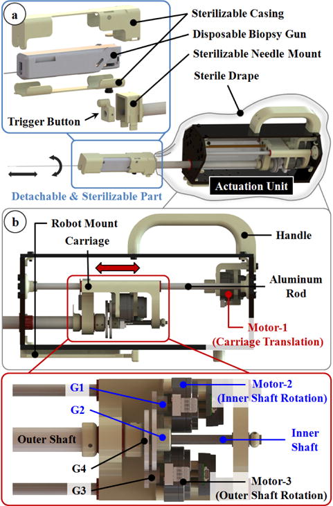
The needle driver module: (a) The biopsy gun is held in a casing that slides and clicks onto the module. (b) 3 non-magnetic ultrasonic motors are used to provide axial rotation, translation and triggering functions without disrupting MRI compatibility.
Similar to the base robot, actuation of the needle driver module is provided by 3 non-magnetic ultrasonic motors (USR30-S4N, Shinsei Co., Tokyo, Japan). Motor-1 in Fig. 2b is used to insert and remove the needle. It is located at the back of the module and rotates a lead screw to translate a carriage back and forth. The carriage slides on two parallel aluminum rods along the module within a range of 130 mm, which is sufficient for typical prostate biopsies. Mounted on the carriage are the other 2 motors (motor-2 and motor-3 in Fig. 2b), which rotate two concentric shafts, separately. The inner shaft is an aluminum rod. It is threaded at its distal tip forming a short power screw for moving the trigger button. The gears G1 and G2 in Fig. 2b provide a reduction ratio of 1:2 between the inner shaft and motor-2. When rotated, the threaded end of the inner shaft translates the trigger button inside the needle mount. The gear reduction combined with the power screw generates sufficient force (20 N using ACECUT automatic biopsy system by TSK Laboratory, Japan) to fire the biopsy gun by pushing the trigger located at its back. Driving the trigger button forth fires the biopsy gun to take a tissue sample. The tubular outer shaft carries the needle mount, thus the entire biopsy gun assembly. Motor-3 in Fig. 2b is connected to the outer tube via the gears G3 and G4 (reduction ratio=1:2), provides axial rotation (360°) of the biopsy (or brachytherapy) needle. This DOF is essential for needle steering since the orientation of the bevel needle tip directly defines the insertion direction. The motion of each motor is tracked by a rotary incremental quadrature encoder (E8P-512, US Digital, Vancouver, Washington). For homing the mechanism, digital fiber optic sensors serving as limit switches are used (FU-38, Keyence Co., NJ, US).
B. Controller
The controller of our needle driver module performs three main functions: (1) It receives control orders from a PC tower, sends encoder readings and limit switch states back. (2) It runs the motors and processes the encoder readings of the driver module. (3) It monitors the motion state through the optical limit switches and confines the motion to the designed range for safe operation.
The controller hardware, shown in Fig. 3, consists of (1) three motor drivers (D6030, Shinsei Co., Tokyo, Japan), (2) a 4-axis DMC-2143 Ethernet motion controller with ICM-20105 opto-isolated I/O module (Galil Motion Control, Rocklin, CA, USA), (3) a media converter (B&B Electronics Mfg. Co., Ottawa, IL, Canada) connecting the Galil controller and the PC outside the MRI room via fiber-optic cables, and (4) a custom-developed command signal converter based on an Arduino Nano platform serving as a translator between the Galil Controller and motor drivers. Additionally, there are two optical limit switch processors (FS-N11P, Keyence Co., NJ, US) and a 24V to 5V DC-DC converter. All these components are shielded in an aluminum casing to minimize the electromagnetic interference during use inside the MRI room. The controller communicates with the PC tower in the control room via optical cables. A 24V power supply is transmitted from the control room to the controller in the MRI room. Most parts in the controller consume 24VDC power except the command signal converter which works under 5VDC, thus a 24V to 5V DC-DC converter is engaged.
Fig. 3.
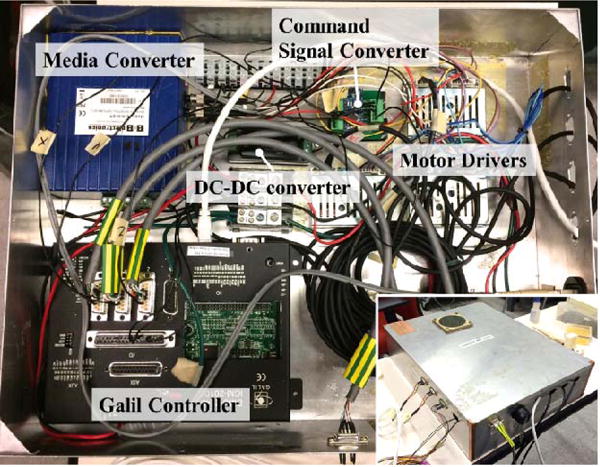
Main components of the controller. The aluminum casing minimizes electro-magnetic interference and enables use inside the MRI room.
An essential part of the control system is the command signal converter. The input control signal for each Shinsei driver includes a 0-3.3VDC speed signal accompanied by two 5V TTL signals defining the direction of rotation. The Galil controller commands lead to ±10VDC signals, which is not appropriate for controlling the Shinsei drivers. We designed and implemented a signal converter between the Galil controller and the motor drivers to map the −10~10VDC signal range linearly into a 0-3.3VDC signal range, with two direction signals at the same time. The core idea is utilizing Analog-Digital (A-D) converters inside an Atmel AVR chip (the main processor on Arduino kits) and generating speed signals by PWM waves. The architecture of the converter board is shown in Fig. 4.
Fig. 4.
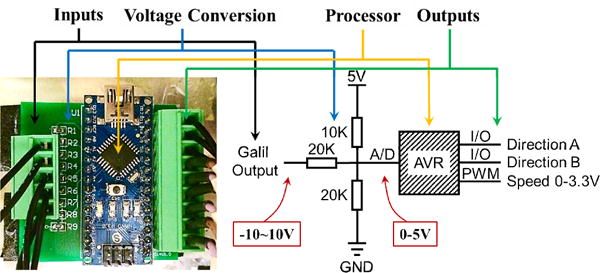
The architecture of the custom command signal converter.
C. System Workflow and Control Scheme
The workflow associated with the proposed system (after acquiring pre-procedural MRI volume of the anatomy and defining the clinical targets) is as follows:
The base robot (BR) and the needle driver module (NDM) are draped in a sterile cover.
BR and NDM are homed to their zero configurations. NDM homing procedure, shown in the video attachment, is completed after the following steps: (a) The carriage is drawn back until activating the optical limit switch on the linear stage; (b) The outer shaft is rotated until activating the limit switch on the carriage; (c)The trigger button, which is used to fire the biopsy gun, is installed on the threaded end of the inner shaft by rotating motor-2until it reaches the base of the needle mount.
BR is placed in the MRI bore between the patient legs.
The biopsy gun/brachytherapy needle is mounted on NDM as in Fig. 2a.
NDM is attached on BR, via the quick-release mechanism (robot mount in Fig. 2b).
BR is positioned for targeting.
The biopsy/brachytherapy needle is inserted using NDM under MRI guidance.
After the clinical target is reached, biopsy gun is triggered or brachytherapy seeds are delivered.
NDM is driven back and detached from BR; then the biopsy gun/brachtherapy needle is taken out.
If another insertion is required, a new needle is placed in the casing (Fig. 2a) and steps 4–10 are repeated.
During the needle insertion phase of this workflow (step 7), the needle orientation needs to be adjusted to avoid obstacles, thus to reach the target via needle steering. Based upon the acquired MRI data, this step can be accomplished in three different ways: (1) Image guided discretized insertion: The clinician inserts the needle step-by-step, observing the needle deflection behavior from the acquired images, and makes decisions to reorient the needle when necessary; (2) Software-assisted discretized insertion: Based upon the target location, obstacles and the implemented needle bending model, a planning software computes the optimal needle trajectory and advises the clinician on when to rotate the needle. The software updates this trajectory using the acquired images; (3) Automatic continuous insertion: After the target and the obstacles in the anatomy are defined by the clinician, the robotic system computes the trajectory, performs the insertion autonomously with imaging feedback.
Among the three alternatives, the former two are preferable as they keep the clinician in the control loop, thus they are inherently safer. Currently, our system runs based upon the first scheme, which is sufficient to test the feasibility of the proposed setup, as the main purpose of this paper. Model based software assistance methods will be integrated upon verification of clinical compatibility.
D. Graphical User Interface
The graphical user interface (GUI) functions as both the control center and the monitor panel providing visual feedback during the procedure. The monitored GUI parameters are the insertion depth and the rotation angle. These values are updated based on encoder readings. An initiatory GUI is shown in Fig. 5b. For control, there are three sets of push buttons corresponding to each DOF of the driver module. There are also buttons for initializing the system and guiding the workflow. A series of elaborated logical locks are set to the buttons to strengthen safety of the system. For instance, if the biopsy gun trigger button is pushed, the needle motion commands are disabled. Table I explicates the function of each button. Hotkeys are added to each button enabling the clinician to interact with the system via an MRI-compatible keyboard — an intuitive, inexpensive yet reliable platform that is easy to integrate, instead of a sophisticated haptic interface as in [13]. This transforms the insertion of the needle into a step-by-step procedure, where each clicking of the insertion button provides either a 5 mm or a 1 mm-deep insertion. As opposed to continuous insertion, this gives the operator more time to observe the needle behavior, thus making safer decisions. In the future, the insertion step will be further optimized for the clinicians’ convenience.
Fig. 5.
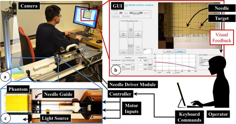
The information flow during needle insertion trials on a soft plastic phantom using the developed needle driver module with visual feedback. (a) The experimental setup using an 18 G biopsy gun. (b) The user interface showing the target location and current needle position for visual feedback to the operator. (c) A detailed view of the operation site while inserting a 20 G brachytherapy needle.
TABLE I.
Needle Control Functions in GUI
| Needle Driver Control | GUI Button | |
|---|---|---|
| Homing | All DOFs to Home Position | |

|
Translation | Insertion (1mm or 5mm) |
| Extraction | ||

|
Axial Rotation | +180° Rotation |
| −180° Rotation | ||

|
Biopsy Gun Trigger | Trigger Activation |
| Trigger to Home Position |
III. Experiments
A. Repeatability and Accuracy Experiments
The precision assessment of the base robot had already been studied in [15]. The goal in this experiment was to analyze the repeatability and accuracy of the needle driver module. A caliper (500-196, Mitutoyo Co., Japan, resolution 0.01 mm), a dial indicator (543-693B, Mitutoyo Co., Japan, resolution 0.001 mm), and a laser level (#0675, Checkpoint Inc., precision 0.1 degree) were used in the measurements. The caliper was used to obtain the distance between the needle mount and the needle driver body after each homing procedure. To determine the translational motion accuracy, the dial indicator was fixed in front of and in contact with the needle mount. The level was attached on the upper flat surface of the needle mount and showed the rotation angle at the end of each motion.
B. Needle Steering Experiment
Goal
Needle steering experiments were carried out to test the feasibility of the needle driver module using visual feedback. The goal in this experiment was to insert a bevel-tip needle into a soft tissue phantom and bring its tip as close to a predefined target within the phantom as possible using the developed robotic system.
Setup
As shown in Fig. 5a, the needle driver was mounted on a fixed platform with a needle guide. An isotropic phantom made of plastic (M-F Manufacturing Company, TX, US, super soft plastic and hardener ratio 3:2), was used to simulate soft tissue. The phantom was molded in an acrylic rectangular box with small holes on the sides serving as needle insertion ports. The dimension of the phantom was 120×80×20mm. A digital camera (USB2-MIRCO-200X, Plugable Technologies) was engaged to capture images of the needle trajectory with a frequency of 10 frames per second. It was fixed above the phantom at a proper height to capture the entire insertion region clearly. The images were fed into the GUI for visual feedback to the operator. A flat panel light source was placed under the phantom to enhance vision contrast of the needle in the image.
Procedure
The operators controlled the needle driver module using a keyboard and monitored the needle advancement from the GUI. The target position was marked on the GUI, and remained fixed during each insertion. The challenge was to examine the deflection of the needle as it was inserted into the phantom, predict its trajectory, and steer it toward the target by rotating the needle to change its bevel direction. Needle steering in this experiment was confined to the horizontal plane by adjusting the bevel direction facing always sideways, so that the camera above the phantom could accurately capture the needle bending behavior.
In needle steering applications, retracting and reinserting the needle, and rotating it excessively often increase tissue damage [16], thus needs to be avoided. In our experiments, we allowed for only one-time rotation (180°) of the needle, which is the minimum number required for steering the needle toward the target in a plane. After beginning the insertion, the operator was not allowed to retract the needle back. The operator needed to predict the critical turning point based on the observed deflection behavior, stop the insertion, rotate the needle 180°, and continue the insertion until reaching the target depth.
The experiment consisted of two consecutive sets of three needle insertions. The first set of insertions used an 18 gauge (18 G) biopsy needle (TSK Laboratory, Japan, tip angle 30 degrees), while the second set used a thinner 20 gauge (20 G) brachytherapy needle (E-Z-EM Incorporation, NY, US, tip angle 45 degrees) (Fig. 5a, 5c). These needles have different flexural stiffness, thus exhibit different bending behavior when inserted into the phantom. Four users with no prior clinical experience performed three insertions per needle type trying to reach a different target position each time. In total, the same set of targets were tested with each user and for each needle type. However, the target was altered between trials in random order to negate the effects of a learning curve in our results. A different hole on the phantom box was used for each trial to prevent interference from neighboring trajectories due to prior insertions. At the end of each trial, the image showing the final needle configuration was recorded for analysis.
Data Analysis
The targeting errors were analyzed by computing the lateral offset between the needle tip and the target position for each needle type, and for each target. For this, a sub-function was added on the GUI that computed the loci of the points on the needle trajectory by retrieving the corresponding pixels on the recorded images. 37 pixels on the image represent 1 cm in reality. Thus, each pixel corresponds approximately to 0.27 mm on the phantom. Compared with the needle diameters (1.3 mm for 18 G, and 0.9 mm for 20 G) and scale of our phantom, this resolution provides sufficient accuracy during point retrieve.
Two coordinate frames were involved in the image processing procedure (Fig. 6): camera image frame (Oc), and needle frame (On). The needle frame origin and orientation was set manually by picking points on the acquired image. This defined the transformation from On to Oc: in (1), where, and are the rotation and translation components, respectively.
| (1) |
Fig. 6.
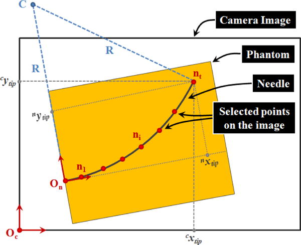
Parameters involved in the computation of radius of curvature (R) and the needle tip position [nxtip nytip] based upon the captured camera images during needle insertion trials.
Then points on the needle trajectory were selected which gave ni coordinates in the camera image frame. Using (2), the points were transformed into the needle frame.
| (2) |
Since the target position in our insertion trials was defined relative to the insertion port on the phantom, thus in the needle frame, this transformation was necessary while computing the error between the needle tip and the target positions.
Based on the observation in [3], regardless of the needle gauge, a bevel-tip needle inserted straight into a soft homogeneous phantom without any rotations follows a circular trajectory. As the needle is pushed in, the proximal section of the needle keeps following the path generated by the distal section. The curvature of the circle indicates the relative stiffness property between the needle and the tissue. In our trials, the GUI sub-function computes the radius of the curvature based upon the selected points on the insertion trajectory.
IV. Results and Discussion
A. Repeatibility and Accuracy Experiments
The tests reported in this section were done by running the system under no external forcing. The reported values here demonstrate the inherent errors due to system components (gear backlash, optical limit switch and encoder resolution), and do not involve the potential deflection of ABS components due to external forces, which will be studied in combination with the base robot to reveal the overall consistency and reliability.
After homing the needle driver module 10 times consecutively, the maximum deviation observed for the linear stage position was 0.04 mm, and for the rotary stage angle was 0.2°. Giving the linear stage random travel commands of up to ±10 mm, and measuring the amount of actual travel with the caliper, we observed a mean error of 0.025 mm, while the maximum error was 0.068 mm in 15 consecutive trials. For the rotary stage, 15 random commands varying from −360° to +360° produced a mean error of 1.0°. The maximum error was 2.1°, which can be attributed to the gear backlash of about 1°.
B. Needle Steering Experiment
The results of our needle insertion trials using the biopsy needle, and the brachytherapy needle are shown in Figs. 8a and 8b, respectively. Using the biopsy needle, most insertions reached a close proximity to the target locations (Fig. 8a). The average error considering all of the users and targets was measured as 0.92 mm (Fig. 9). On the contrary, the overall average error in the trials performed with the thinner brachytherapy needle was 1.65 mm. The range of final needle tip position was also visibly larger (Fig. 8b), especially for the deepest target (T3) requiring a 110 mm insertion. The mean error for this target was 0.96 mm using the biopsy needle as compared to the 2.61 mm mean error with the brachytherapy needle. This can be attributed to the deflection behavior difference between the two needles. As shown in Fig. 7, when inserted straight into the phantom, the 20 G brachytherapy needle bends significantly more than the 18 G biopsy needle. The mean radii of curvature for the 18 G and 20 G needles in this particular soft plastic phantom were respectively as 875 mm and 608 mm. Since the brachytherapy needle is much more flexible and bends more, rotating the needle even slightly before or after the optimal location will result in a larger deviation from the target. Thus, the targeting accuracy for this type of needle is very sensitive to the timing of needle rotation, and requires much more careful planning of the steering action.
Fig. 8.
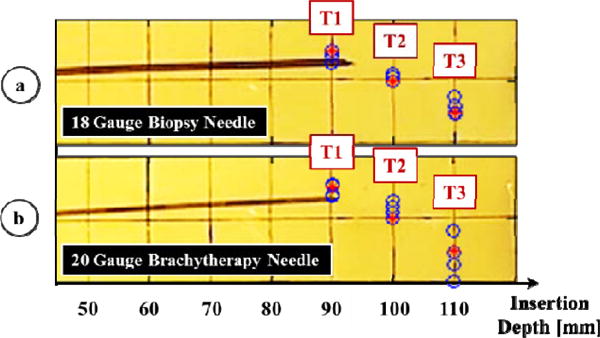
Results of needle steering using (a) an 18 G biopsy needle and (b) a 20 G brachytherapy needle. Measured needle tip positions at the end of each insertion are shown in blue. The three target loci (T1, T2, T3) are marked in red, requiring 90, 100, and 110 mm depth of insertions respectively. Higher targeting accuracy was obtained in 18 G biopsy needle trials.
Fig. 9.
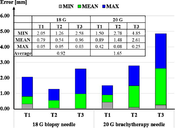
Errors computed in needle steering toward targets T1, T2 and T3 using an 18 G biopsy needle vs. a 20 G brachytherapy needle. Overall, larger targeting errors were observed for the latter.
Fig. 7.
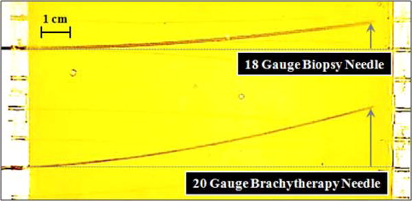
Deflection behavior of an 18 G biopsy needle vs. a 20 G brachytherapy needle in a soft plastic phantom. When inserted without any rotations, the 20 G brachytheraphy needle bends significantly more. The radii of curvature were computed respectively as 875 mm and 608 mm.
V. Conclusion
This paper presented an MRI-compatible needle driver designed for our former prostate intervention robot, which we currently are developing toward clinical use. In accordance with the clinical workflow and MRI compatibility requirements, mechanical design, controller architecture and system integration were explicated. The novel features of the presented approach are: (1) the modular design eliminates the need of moving the patient out of the MRI bore repeatedly throughout multi-biopsy procedures; (2) the step-by-step insertion strategy keeps clinician in the control loop, which provides operation safety; (3) the needle driverI module can manipulate a standard biopsy gun and therefore can be integrated easily into current clinical practice.
Our preliminary experiments demonstrated the accuracy of the system and its feasibility for reaching targets in an artificial phantom via 2D needle steering. The operators could reach approximately 100 mm deep targets with a mean error of 0.92 mm for 18 G needles and 1.65 mm for 20 G needles. Our current studies aim at extending these results and further evaluating the system through IRB-approved multiple-subject experiments, in which multiple needle rotations are allowed and operators’ behavior on making decisions and correcting errors under visual feedback are observed. This is an ongoing work, and future tasks involve evaluation of 3D needle deflection models and integration of model-based path planning algorithms into the control scheme. This will assist operators during insertion by suggesting to them when to rotate the needle for higher targeting accuracy with minimal tissue damage.
Acknowledgments
The authors thank Michael Pozin for his contributions in setting up the experiments.
Footnotes
Research supported in part by the National Institutes of Health under R01 CA111288 and in part by Johns Hopkins University internal funds. Meng Li is supported by China Scholarship Council.
References
- 1.DiMiao SP, Salcudean SE. Needle steering and model-based trajectory planning. Proceedings of the Medical Image Computing and Computer-Assisted Intervention. 2003:33–40. [Google Scholar]
- 2.Glozman D, Shoham M. Flexible needle steering and optimal trajectory planning for percutaneous therapies. Proceedings of the Medical Image Computing and Computer-Assisted Intervention. 2004:137–144. [Google Scholar]
- 3.Webster RJ, Kim JS, Cowan NJ, Chirikjian GS, Okamura AM. Nonholonomic modeling of needle steering. The International Journal of Robotics Research. 2006 May;25(5–6):509–525. [Google Scholar]
- 4.Patil S, Alterovitz R. Interactive motion planning for steerable needles in 3D environment with obstacles. Proceedings of the International Conference on Biomedical Robotics and Biomechatronics. 2010:26–29. doi: 10.1109/BIOROB.2010.5625965. [DOI] [PMC free article] [PubMed] [Google Scholar]
- 5.Seifabadi R, Song S-E, Krieger A, Cho NB, Tokuda J, et al. Robotic system for MRI-guided prostate biopsy: feasibility of teleoperated needle insertion and ex vivo phantom study. International Journal of Computer Assisted Radiology and Surgery. 2012 Mar;7(2):181–190. doi: 10.1007/s11548-011-0598-9. [DOI] [PMC free article] [PubMed] [Google Scholar]
- 6.Fichtinger G, DeWeese TL, Patriciu A, Tanacs A, Mazilu D, Anderson JH, et al. System for robotically assisted prostate biopsy and therapy with intraoperative CT guidance. Academic Radiology. 2002 Jan;9(1):60–74. doi: 10.1016/s1076-6332(03)80297-0. [DOI] [PubMed] [Google Scholar]
- 7.Podder TK, Beailieu L, Caldwell B, Cormack RA, Crass JB, et al. AAPM and GEC-ESTRO guidelines for image-guided robotic brachytherapy: report of task group 192. The International Journal of Medical Physics Research and Practice. 2014 Oct;41(10):101501. doi: 10.1118/1.4895013. [DOI] [PubMed] [Google Scholar]
- 8.Su H, Shang W, Cole G, Li G, Harrington K, Camilo A, et al. Piezoelectrically actuated robotic system for MRI-guided prostate percutaneous therapy. IEEE/ASME Transactions on Mechatronics. 2014 Nov;1(1):1–12. doi: 10.1109/TMECH.2014.2359413. [DOI] [PMC free article] [PubMed] [Google Scholar]
- 9.Shang W, Su H, Li G, Fischer GS. Teleoperation system with hybrid pneumatic-piezoelectric actuation for MRI-guided needle insertion with haptic. International Conference on Intelligent Robots and System. 2013:4092–4098. doi: 10.1109/IROS.2013.6696942. [DOI] [PMC free article] [PubMed] [Google Scholar]
- 10.Burbank FH, Fogarly TJ, Manska WE, Ritchart MA, Ryan TJ, Zerhouni EA. Apparatus for automated biopsy and collection of soft tissue. US5775333A. U.S. Patent. 1998 Jul 7;
- 11.Moon Y, Choi J. Development of a robotic mechanism for teleoperation-based needle interventions. 44th International Symposium on Robotics (ISR) 2013:1–3. [Google Scholar]
- 12.Stoianovici D, Song D, Petrisor D, Ursu D, Mazilu D, et al. “MRI Stealth” robot for prostate interventions. Minimally Invasive Therapy & Allied Technologies. 2007;16(4):241–248. doi: 10.1080/13645700701520735. [DOI] [PMC free article] [PubMed] [Google Scholar]
- 13.Seifabadi R, Iordachita I, Fichtinger G. Design of a teleoperated needle steering system for MRI-guided prostate interventions. Proceedings of the International Conference on Biomedical Robotics and Biomechatronics. 2012:793–798. doi: 10.1109/BioRob.2012.6290862. [DOI] [PMC free article] [PubMed] [Google Scholar]
- 14.Eslami S, Fischer GS, Song S-E, Tokuda J, Hata N, et al. Toward clinically optimized MRI-guided surgical manipulator for minimally invasive prostate percutaneous interventions constructive design. International Conference on Robotics and Automation. 2013:1228–1233. doi: 10.1109/ICRA.2013.6630728. [DOI] [PMC free article] [PubMed] [Google Scholar]
- 15.Eslami S, Shang W, Li G, Patel N, Fischer GS, Tokuda J, et al. In-bore prostate transperineal interventions with an MRI-guided parallel manipulator: system development and preliminary evaluation. International Journal of Computer Assisted Radiology and Surgery. 2015 doi: 10.1002/rcs.1671. in press. [DOI] [PMC free article] [PubMed] [Google Scholar]
- 16.Swaney PJ, Burgner J, Gilbert HB, Webster RJ. A flexure-based steerable needle: high curvature with reduced tissue damage. IEEE Transaction on Biomedical Engineering. 2012 Nov;60(4):906–909. doi: 10.1109/TBME.2012.2230001. [DOI] [PMC free article] [PubMed] [Google Scholar]
- 17.NEMA. Determination of two-dimensional geometric distortion in diagnostic magnetic resonance images. Vol. 2. National Electrical Manufacturers Association Standards Publication MS; 2008. [Google Scholar]


