Abstract
The use of a phased array of ultrasound transducer elements to sonicate through the skull has opened the way for new treatments and the delivery of therapeutics beyond the blood-brain barrier. The limited steering range of current clinical devices, particularly at higher frequencies, limits the regions of the brain that are considered treatable by ultrasound. A new array design is introduced that allows for high levels of beam steering and increased transmission throughout the brain. These improvements are achieved using concave transducers normal to the outer-skull surface in a patient-specific configuration to target within the skull, so that the far-field of each beam is within the brain. It is shown that by using pulsed ultrasound waves timed to arrive in-phase at the desired target, sufficient levels of acoustic energy are delivered for blood-brain barrier opening throughout the brain.
1. Introduction
The application of focused ultrasound to the brain through the intact skull has a long history leading up to the clinical implementations of the present day. Since the first successful ablation of animal brain tissue transcranially using a single transducer in 1980 (Fry & Goss 1980), to the present day clinical treatments of essential tremor using hemispherical phased arrays consisting of more than one thousand elements (Elias et al. 2016), new phased array designs have been conceptualized to overcome previous challenges. Previous developments include skull aberration correction (Thomas & Fink 1996, Hynynen & Jolesz 1998, Clement & Hynynen 2002), standing wave reduction (Song et al. 2012), skull heating minimization (Sun & Hynynen 1999, Clement & Hynynen 2000), and dual-frequency blood-brain barrier (BBB) opening (Liu et al. 2014).
Most of the current clinical work in transcranial focused ultrasound involves continuous wave ultrasound to cause thermal ablation (McDannold et al. 2010, Jeanmonod et al. 2012, Jung et al. 2015, Elias et al. 2016). Early animal studies, however, have shown that burst ultrasound could be used for BBB opening (Vykhodtseva et al. 1995, Hynynen et al. 2001). This has led to studies involving BBB opening in conjunction with drug delivery to treat brain tumors (Treat et al. 2007) and Alzheimer’s disease (Jordão et al. 2010) and deliver immune cells to metastatic brain tumors (Alkins et al. 2013), among others. A recent study has even shown that mechanical tissue destruction is possible with lower intensity pulsed ultrasound when used in conjunction with microbubbles (Huang et al. 2013, McDannold et al. 2013). In these applications, skull heating is of minimal concern due to the low duty cycle.
To obtain maximal energy transmission through the skull, the wave should enter the skull at normal incidence (Clement & Hynynen 2002). This limits the areas of skull that can be used for ideal power transmission to the target region - especially for targets that are not in the central regions of the brain. Here, we propose a new approach using concave transducers focusing their beam inside the skull, such that the planar wave at the focus penetrates the skull at normal incidence. With the proper design, the planar waves propagate through the skull and exit the brain as diverging waves, thereby minimizing the impact of the impedance mismatch with bone. By using an array of such transducers and timing the bursts such that they arrive at the desired target simultaneously, one would expect an acoustic focus to be generated. In this numerical study, the feasibility of this idea in a realistic skull geometry is explored.
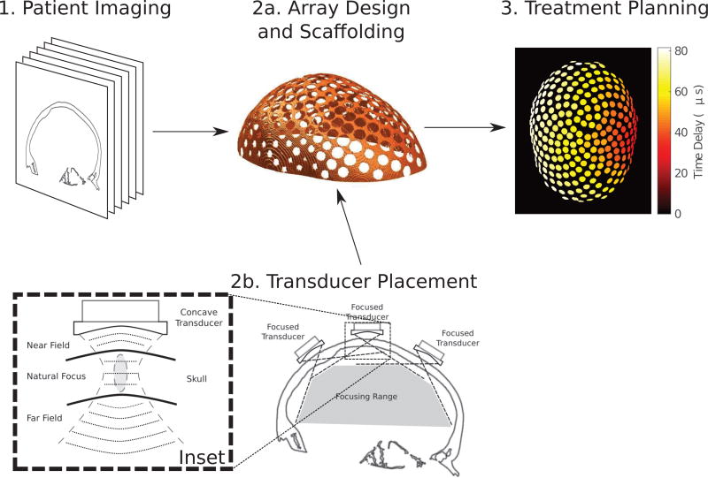
In clinical practice, an array scaffold would be constructed from imaging data to fit the patient, followed by the placement of the curved transducer elements within the scaffold. Finally, upon fixing the array to the patient head at the time of treatment, a final imaging sequence would be obtained for use in computer-assisted treatment planning. The workflow of the proposed treatment process is outlined in Figure 1.
Figure 1.
The treatment workflow using a patient-specific array: (1) 3-dimensional patient imaging for scaffold design; (2a) the construction of a phased array scaffold for transducer placement; (2b) the placement of focused transducer elements within the scaffold, where the inset illustrates the concept of focusing inside the skull at normal incidence to increase the steering range and transmission; and (3) computer-assisted treatment planning to control the time delays on each element in the array to steer the beam to a lateral target in the brain, shown as a maximum-intensity projection of the time delays on each element.
2. Materials and Methods
2.1. Array Design
The concept of the array design and resultant treatment workflow is illustrated in Figure 1, where a concave transducer is positioned such that the natural focus of the transducer is inside the skull. In this way, the brain is within the far-field of the transducer. With proper transducer design, the majority of trans-skull transmission should be planar waves in the process of converting from convergent to divergent wavefronts. This planar transmission at normal incidence should then theoretically result in higher trans-skull transmission and a larger steering range, compared to a hemispherical array with the same number of elements.
In setting up the transducer array geometry, the number of transducers in the array was considered fixed. That is, an array was determined to have N elements of some size in some configuration, and focusing at some variable depths within the skull. Once the number of transducers was determined, the positions were assigned using Vogel’s method (Vogel 1979), such that the placement was optimally random and spaced out as far as possible given N. Given these fixed distances, the maximum transducer area was determined, with consideration being given to engineering limitations of inter-element spacing, such that a reasonable gap was left. All transducers in each array were of the same size.
The incidence angle to the skull surface at the closest point to the transducer center was determined, and each transducer was rotated independently, such that the transducer was of normal incidence to the skull surface. Each transducer was then shifted towards or away from the skull surface in order to achieve identical distances with the midpoint of the skull. The fixed distance from the skull was based on trial and error to determine the closest reasonable position of the transducer elements to the skull. This minimum distance was found to vary depending on both the total number of transducers in the array and the concavity of each transducer.
In this way, all transducer elements were set approximately normal to the skull surface and approximately equidistant to the skull focus point.
2.2. Patient Treatment Modeling
A CT scan (LightSpeed VCT, GE Healthcare, Chalfont St Giles, UK) of a human cadaver skull was obtained and used in each of the numerical simulations (512 × 512 × 328 voxels with uniform voxels of size 625 × 625 × 625 µm3). The density was obtained using a linear relation with the Hounsfield Units, using knowledge of the densities of water and air in the CT scan (Connor et al. 2002). The skull CT data was then segmented in MATLAB (The Mathworks Inc., Natick, MA, USA) and interpolated such that the discretization in the numerical simulations was λ/10, where λ was the wavelength of the ultrasound in water.
A previously-introduced numerical model (Pulkkinen et al. 2014), which combines finite difference simulations (Croft 1977) with the grid method (Zhang 2004), was modified to allow for ultrasound bursts of variable length to be emitted from the transducer elements in the array. Details of the numerical implementation of these acoustic simulations are given elsewhere (Pulkkinen et al. 2014, Hughes et al. 2016). A Fast Fourier Transform of the peak cycle of the acoustic field was taken to obtain the time-averaged pressure field over the treatment domain. Each simulation was run over a sufficient number of temporal steps to allow the ultrasound wavefront from each element to reach the target. The phasing of each transducer element was obtained by first sending a pulse from the target focus in the brain, and delaying the transmission pulse based on the time-of-flight obtained to each element. Each sonicating transducer element was then driven with the time-delayed Gaussian-enveloped sinusoidal signal obtained from the reversed problem. All sonications were performed with a 3-cycle pulse unless otherwise specified.
Thermal simulations were performed in the cranial bone, using the absorbed power density obtained from (Hosten et al. 2008). The absorbed power density was then used as a heat source in the Pennes bioheat equation (Pennes 1948). The temporal evolution of this equation was solved using a finite-difference time-domain (FDTD) technique.
A computer cluster consisting of eight Intel Xeon processors was used to perform the simulation of the FDTD simulations, while a standard desktop computer was used to analyze and process the data.
2.3. Safety Analysis
In order to assess the potential safety of the sonications to brain tissue, the ratio of the peak pressure amplitude at the focus to the maximum pressure at the inner-surface of the skull was analyzed, in order to assess the acoustic energy deposition away from the focus. This ratio was described as the array gain, GMAX.
3. Results
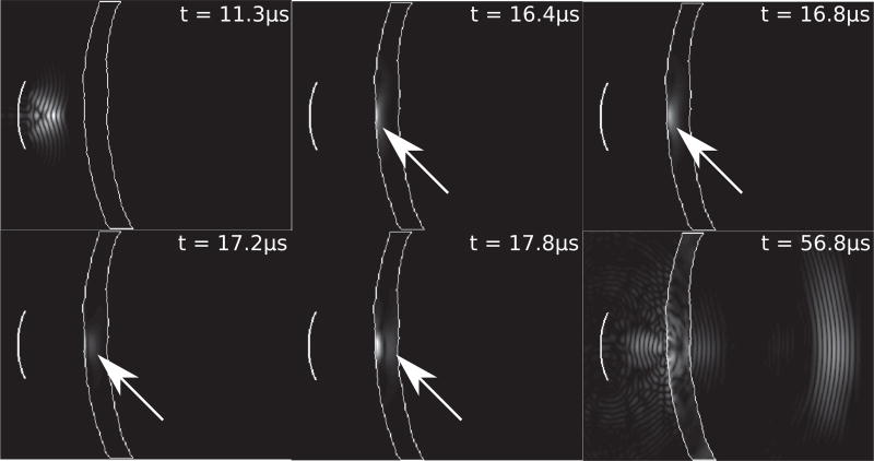
Emphasizing the wave conversion presented in Figure 1, Figure 2 illustrates the propagation of the ultrasonic wave through the skull, emphasizing the conversion to plane wave propagation. The transducer (f-number=1, radius=10 mm, f=500 kHz) is focused inside the skull. The outline of the skull is shown in white. At 16.4 µs, the converging spherical wave is converted to a planar wave which then propagates at normal incidence through the skull, as highlighted at t = 16.8, 17.2, and 17.8µs with the white arrows. At 56.8 µs, the attenuated wave is shown inside the head as a diverging spherical wave. The particle displacement fields inside the skull are scaled for visual contrast with the pressure field.
Figure 2.
An illustration of the temporal wave propagation of a 5-cycle pulse emitted from a single curved transducer (f-number=1, radius=10 mm, f=500 kHz) focused inside the skull, at timepoints 11.3, 16.4, 16.8, 17.2, 17.8, and 56.8 µs.
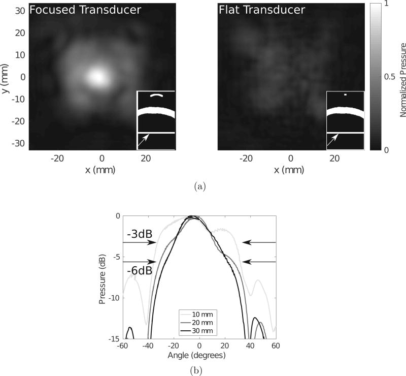
To illustrate the increased transmission resulting from this wave conversion in the skull, Figure 3a compares a concave transducer focused inside the skull to a flat λ/2-diameter element. Both transducer powers are normalized to the same value, and the pressure fields are taken as ratios to the maximum pressure in the focused transducer case. The panels in each subfigure illustrate schematics of the geometry through the coronal plane, with the arrows pointing to the position of the transverse plane through which the pressure maps are displayed. It is clear in this example that the curved transducer transmits a higher intensity acoustic field through the skull, with a more disperse acoustic field than the flat transducer of size λ/2. Figure 3b demonstrates the effect of the focal lengths listed in the legend on the angle of dispersion of the acoustic field for a transducer of diameter 20 mm. It is clear that the −3 dB and −6 dB beamwidths are increased when the transducer is more concave, as highlighted by the arrows.
Figure 3.
(a) A comparison between a focused (left) and flat, λ/2-diameter (right) transducer and (b) a comparison between the beamwidths of transducers with different focal lengths for a 20 mm-diameter transducer, with the −3dB and −6dB widths indicated by the arrows.
Figures 2 and 3 demonstrate that focusing a wavefront through the skull allows for dispersion of the wave within the head, as well as an increased transmission as compared to a single small element.
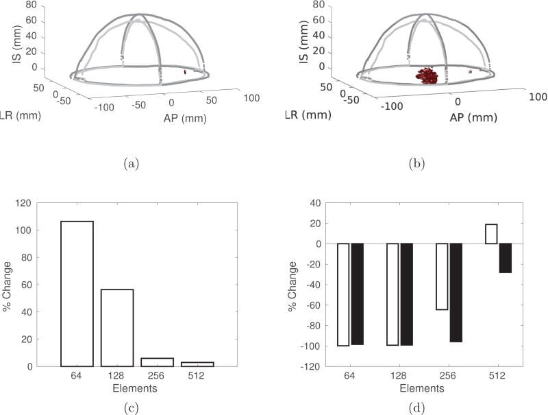
Figure 4 summarizes the advantages of a conformal array to a hemispherical array. The −3dB isosurfaces for a conformal (Figure 4a) and a hemispherical (Figure 4b) array illustrate the improvement in focusing when using only 128 elements. Figure 4c shows the percentage increase in the transmitted intensity at a lateral brain target when using a conformal array as compared to a hemispherical array. Figure 4d shows the percentage change in the −3dB (white) and −6dB (black) volumes, illustrating the improvement in focal quality when using a conformal array.
Figure 4.
The −3 dB isosurfaces for (a) the conformal array and (b) the hemispherical array, with 128 elements, and the percentage change in (c) the intensity and (d) the −3dB (white) and −6dB (black) volumes, as a function of the number of elements, when comparing the conformal array to a hemispherical array. In all cases, the focus is positioned at (AP = +60 mm, LR = 0, IS = 0), where (0, 0, 0) is the geometric center of the brain, to demonstrate the steering capabilities of the conformal array.
3.1. Safety Analysis
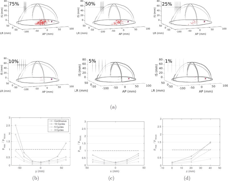
The primary safety concern is the deposition of acoustic energy at locations away from the target focus. Figure 5a illustrates the effect of the duty cycle on the focusing quality, for duty cycles of 75, 50, 25, and 10 %. The red indicates the −6 dB isosurface, and the blue indicates the −3 dB isosurface. In all four cases, the −3 dB isosurface is contained to the vicinity of the target, whereas the −6 dB isosurface is widely dispersed for 50 and 75 % duty cycles, and minimal for less than 25 % duty cycles. It is therefore imperative that the sonication duty cycle be reduced in order that acoustic energy is not deposited to central regions of the brain when targeting to lateral positions. Figures 5b, 5c, and 5d further this point, by presenting the peak pressure in the brain compared to the target focus for bursts of 3, 5, and 10 cycles, and continuous-wave sonication. These figures demonstrate that shorter pulse lengths are ideal for more lateral targets in the brain, to avoid accumulation of acoustic energy away from the target focus.
Figure 5.
(a) The effect of duty cycle on the −3 dB (blue) and −6 dB (red) isosurfaces, and (b–d) the ratio between the maximum acoustic pressure in the brain compared to the target focus, for a 256-element conformal array targeted to (AP = +60 mm, LR = 0, IS = 0).
With sufficient temporal spacing to allow for skull cooling, in conjunction with present-day skull cooling mechanisms during treatment, it appears that skull heating would not be a limitation to potential treatments with this device. Using a 256-element array sonicating at 100 W at a frequency of 500 kHz, a single 1000-cycle burst, representing a continuous wave sonication of duration 2 ms, led to a temperature rise of approximately 0.03 °C, while the focal pressure amplitude ranged between 0.24–1.4 MPa for the different steered positions. Naturally, a duty cycle lower than 100% would lead to a smaller temperature rise. In addition, Table 1 illustrates the effect of the number of transducers on the minimum (GMIN) and maximum (GMAX) gain values throughout the head, as well as the minimum (pMIN) and maximum (pMAX) focal pressure amplitudes.
Table 1.
A summary of the minimum (GMIN) and maximum (GMAX) gains, and minimum (pMIN) and maximum (pMAX) focal pressure amplitudes, for different numbers of elements.
| Number of Elements | ||||
|---|---|---|---|---|
| 64 | 128 | 256 | 512 | |
| min(GMAX) | 2.8 | 3.9 | 9.6 | 26.5 |
| max(GMAX) | 7.3 | 11.3 | 56.9 | 140.5 |
| pMAX (MPa) | 0.34 | 0.63 | 1.4 | 1.9 |
| pMIN (MPa) | 0.13 | 0.19 | 0.24 | 0.35 |
4. Discussion
A novel phased array design for transcranial focused ultrasound therapy was presented. This design could extend the limited electronic steering range in the brain by reducing the impact of the high acoustic impedance of the skull on the propagation window and using focused array elements focused in the skull such that the plane waves generated were propagated through the skull. With a sharply-focused transducer, the wave in the far field in the brain diverges, providing an increased steering range. This study also introduced the novel idea of placing the array elements in a patient-specific scaffold, designed to fit tightly around the patients head. This patient-specific transducer helmet could potentially be formed by rapid prototyping it based on MRI- or CT-derived head geometry.
There is potential that this new array design could be used in higher frequency applications requiring low-power, low-duty-cycle applications, including BBB opening. The use of a conformal array of focused transducer elements allows for tight focusing at lateral targets in the brain, with sufficient acoustic pressures for a number of therapies involving relatively short ultrasound pulses, including BBB opening, where sonications were performed at a pressure of 0.54 MPa (O’Reilly et al. 2011), which is within the range of acoustic pressures presented in Table 1. These studies were performed at 1.18 MHz, however, and the required pressures at 500 kHz could be different as a result. Other studies found that at 558 kHz, targeted antibodies reduced Amyloid-β plaque loads while sonicating in 10 ms bursts at 0.3 MPa (Jordão et al. 2010), and blood-brain barrier opening was possible at 0.52 MPa at 600 kHz (Liu et al. 2014). Both of these acoustic pressures are within the pressure ranges presented in this study.
Clinical transcranial therapies are currently performed using hemispherical arrays (McDannold et al. 2010, Jung et al. 2015, Elias et al. 2016), and the performance of conformal arrays compared to hemispherical arrays was summarized in Figure 4. Most importantly, it was shown that with only 64 or 128 channels, precise targeting and high transmission was achieved. With the increased electronic complexity associated with many independent channels, the ability to focus with few elements would make for an array with relatively simple driving electronics. This advancement could allow for ease of adoption of the technology. Interestingly, the margins of improvement in transmission and focusing quality with a conformal array over a hemispherical array decrease as the number of elements is increased. This is hypothesized to be in large part because the curvature of the elements becomes more like the flat elements in the hemispherical array as the number of elements is increased.
The question of how to optimize this configuration for a given patient geometry then arises. For each patient geometry, there is a limited surface area over which to distribute elements in such a conformal configuration. That is, the number of elements is limited by the diameter of each transducer, and the f-number of each transducer is limited by the allowable distance to the skull. In addition, the distance of each element from the skull, for a given f-number, dictates how the wavefront will propagate through the skull, affecting both the transmission as well as the dispersion of the wave inside the head. Figure 3b illustrates the effect of different transducer focal lengths on the dispersion of the pressure wave transmitted through the skull. The advantage of a relatively wide dispersion is that the steering range is increased, since there is minimal natural concentration of acoustic energy in any point in the brain, allowing for tight focusing anywhere in the brain. In addition, Figure 3a clearly demonstrates the benfits of focusing a transducer in the skull to achieve higher transmission and better focus resolution, compared to a λ/2-diameter flat element. The optimal array design that balances degrees of freedom from having more elements with the increased transmission from a larger, more sharply-focused element, remains to be understood.
A limitation of the proposed array construction is the duration of the bursts that can be safely sonicated, as well as the duty cycle of these bursts. Figure 5 showed that with reducing duty cycle, the targeting becomes more accurate, and the peripheral −6 dB volumes decrease. In addition, it seems that only short-duration pulses would allow for precise targeting and the elimination of acoustic depositions at unintended locations in the brain. With a duty cycle of less than 10%, however, acoustic deposition away from the focus was shown to be minimal. As a result, sonications using a short pulse with 10% duty cycle could potentially be used. Skull heating for burst ultrasound was analyzed and found to not cause any safety limitations.
Further, there is the potential for error associated with various stages of the array manufacturing process. The CT images used to construct the skull volume have a resolution of 0.625 mm, and therefore there is the potential maximum 1.08 mm alignment error between the actual skull and the array. In addition, the method of printing the scaffold from the CT DICOM images using a FORTUS 400 3D printer results in a 0.075 mm tolerance.
4.1. Numerical Limitations
The model presented here is a linear simulation of the acoustic field and is valid for the low pressure amplitude sonications investigated here. The utility of the array design for nonlinear applications, including histotripsy and higher power therapies have thus not been simulated. The use of nonlinear simulations, however, would come with additional convergence issues, particularly when coupling the finite-difference simulations with the grid method as performed in this study.
5. Conclusions
A novel phased array design for transcranial focused ultrasound therapy was presented. The use of a conformal array of focused transducer elements allows for tight focusing at lateral targets in the brain, with sufficient acoustic pressures for BBB opening and drug delivery.
Acknowledgments
The authors would like to thank Aki Pulkkinen and Sean Purcell for their technical assistance with the development of the numerical models. Support for this work was provided by the National Institutes of Health under grant number R01-EB003268, as well as the Canada Research Chair Program.
References
- Alkins R, Burgess A, Ganguly M, Francia G, Kerbel R, Wels WS, Hynynen K. Cancer Research. 2013;73(6):1892–1899. doi: 10.1158/0008-5472.CAN-12-2609. [DOI] [PMC free article] [PubMed] [Google Scholar]
- Clement GTG, Hynynen K. The Journal of the Acoustical Society of America. 2000;108(1):441–6. doi: 10.1121/1.429477. [DOI] [PubMed] [Google Scholar]
- Clement GT, Hynynen K. Physics in medicine and biology. 2002;47(8):1219–36. doi: 10.1088/0031-9155/47/8/301. [DOI] [PubMed] [Google Scholar]
- Connor CW, Clement GT, Hynynen K. Physics in medicine and biology. 2002;47(22):3925–44. doi: 10.1088/0031-9155/47/22/302. [DOI] [PubMed] [Google Scholar]
- Croft DR. Heat transfer calculations using finite difference equations. Applied Science Publishers; London: 1977. [Google Scholar]
- Elias WJ, Lipsman N, Ondo WG, Ghanouni P, Kim YG, Lee W, Schwartz M, Hynynen K, Lozano AM, Shah BB, Huss D, Dallapiazza RF, Gwinn R, Witt J, Ro S, Eisenberg HM, Fishman PS, Gandhi D, Halpern CH, Chuang R, Butts Pauly K, Tierney TS, Hayes MT, Cosgrove GR, Yamaguchi T, Abe K, Taira T, Chang JW. New England Journal of Medicine. 2016;375(8):730–739. doi: 10.1056/NEJMoa1600159. [DOI] [PubMed] [Google Scholar]
- Fry FJ, Goss SA. Ultrasound in Medicine and Biology. 1980;6(1):33–35. doi: 10.1016/0301-5629(80)90061-7. [DOI] [PubMed] [Google Scholar]
- Hosten B, Bacon C, Biateau C. The Journal of the Acoustical Society of America. 2008 Dec;124:3491–3496. doi: 10.1121/1.2998392. [DOI] [PubMed] [Google Scholar]
- Huang Y, Vykhodtseva NI, Hynynen K. Ultrasound in Medicine and Biology. 2013;39(8):1420–1428. doi: 10.1016/j.ultrasmedbio.2013.03.006. [DOI] [PMC free article] [PubMed] [Google Scholar]
- Hughes A, Huang Y, Pulkkinen A, Schwartz ML, Lozano AM, Hynynen K. Physics in Medicine and Biology. 2016;61(22):8025–8043. doi: 10.1088/0031-9155/61/22/8025. [DOI] [PMC free article] [PubMed] [Google Scholar]
- Hynynen K, Jolesz FAFFA. Ultrasound in Medicine and Biology. 1998;24(2):275–283. doi: 10.1016/s0301-5629(97)00269-x. [DOI] [PubMed] [Google Scholar]
- Hynynen K, McDannold N, Vykhodtseva N, Jolesz F. Radiology. 2001;220(3) doi: 10.1148/radiol.2202001804. [DOI] [PubMed] [Google Scholar]
- Jeanmonod D, Werner B, Morel A, Michels L, Zadicario E, Schiff G, Martin E. Neurosurgical focus. 2012;32(1):E1. doi: 10.3171/2011.10.FOCUS11248. [DOI] [PubMed] [Google Scholar]
- Jordão JF, Ayala-Grosso CA, Markham K, Huang Y, Chopra R, McLaurin J, Hynynen K, Aubert I. PLoS ONE. 2010;5(5):4–11. doi: 10.1371/journal.pone.0010549. [DOI] [PMC free article] [PubMed] [Google Scholar]
- Jung HH, Kim SJ, Roh D, Chang JGW, Chang WS, Kweon EJ, Kim CH, Chang JGW. Molecular Psychiatry. 2015;20(10):1205–1211. doi: 10.1038/mp.2014.154. [DOI] [PubMed] [Google Scholar]
- Liu HlL, Jan CkK, Chu PcC, Hong JcC, Lee PyY, Hsu JdD, Lin CC, Huang CY, Chen PY, Wei KC. IEEE Transactions on Biomedical Engineering. 2014;61(4):1350–1360. doi: 10.1109/TBME.2014.2305723. [DOI] [PubMed] [Google Scholar]
- McDannold N, Clement GT, Black P, Jolesz F, Hynynen K. Neurosurgery. 2010;66(2):323–32. doi: 10.1227/01.NEU.0000360379.95800.2F. [DOI] [PMC free article] [PubMed] [Google Scholar]
- McDannold N, Zhang YZ, Power C, Jolesz F, Vykhodtseva N. Journal of neurosurgery. 2013;119(5):1208–20. doi: 10.3171/2013.8.JNS122387. [DOI] [PMC free article] [PubMed] [Google Scholar]
- O’Reilly MA, Waspe AC, Ganguly M, Hynynen K. Ultrasound in Medicine and Biology. 2011;37(4):587–594. doi: 10.1016/j.ultrasmedbio.2011.01.008. [DOI] [PMC free article] [PubMed] [Google Scholar]
- Pennes HH. Journal of applied physiology. 1948;1(2):93–122. doi: 10.1152/jappl.1948.1.2.93. [DOI] [PubMed] [Google Scholar]
- Pulkkinen A, Werner B, Martin E, Hynynen K. Physics in medicine and biology. 2014;59(7):1679–700. doi: 10.1088/0031-9155/59/7/1679. [DOI] [PMC free article] [PubMed] [Google Scholar]
- Song J, Pulkkinen A, Huang Y, Hynynen K. IEEE Transactions on Biomedical Engineering. 2012;59(2):435–444. doi: 10.1109/TBME.2011.2174057. [DOI] [PMC free article] [PubMed] [Google Scholar]
- Sun J, Hynynen K. The Journal of the Acoustical Society of America. 1999;105(4):2519–27. doi: 10.1121/1.426863. [DOI] [PubMed] [Google Scholar]
- Thomas JLJL, Fink MAM. IEEE Transactions on Ultrasonics, Ferroelectrics and Frequency Control. 1996;43(6):1122–1129. [Google Scholar]
- Treat LH, McDannold N, Vykhodtseva N, Zhang Y, Tam K, Hynynen K. International Journal of Cancer. 2007;121(4):901–907. doi: 10.1002/ijc.22732. [DOI] [PubMed] [Google Scholar]
- Vogel H. Mathematical Biosciences. 1979;189:179–189. [Google Scholar]
- Vykhodtseva NI, Hynynen K, Damianou C. Ultrasound in Medicine and Biology. 1995;21(7):969–979. doi: 10.1016/0301-5629(95)00038-s. [DOI] [PubMed] [Google Scholar]
- Zhang J. Geophysical Journal International. 2004;159(1):240–252. [Google Scholar]


