 New Ru(ii)–Re(i) diads with bridging ligands constructed of two diimines connected by –CH2OCH2– or –CH2SCH2– were synthesized and investigated as photocatalysts with enhanced oxidation power.
Abstract
We developed Ru(ii)–Re(i) supramolecular photocatalysts in which each metal complex unit is connected by a –CH2XCH2– (X = O, S, CH2) chain. The photocatalyst with X = O exhibited the best photocatalytic efficiency for CO2 reduction in the reported systems using a NAD(P)H model compound as an electron donor because the introduced oxygen atom strengthened the oxidation power of the Ru photosensitizer unit in the excited state and accelerated electron transfer from the one-electron-reduced Ru photosensitizer unit to the Re catalyst unit. In contrast, the catalytic ability of the photocatalyst with X = S rapidly decreased during irradiation because the supramolecular structure split into mononuclear complexes. A detailed mechanism for the efficient photocatalytic reaction involving these supramolecular photocatalysts was investigated for the first time.
Introduction
The conversion of CO2 into high-energy compounds using solar energy is a potential technology for addressing both the problem of global warming and the shortage of fossil fuel resources.1 Some transition metal complexes can broadly absorb visible light and function as redox photosensitizers, which drive one-electron-transfer reactions.2 However, because the reduction of CO2 to stable compounds requires multi-electron insertion into CO2, a catalyst is also required for photocatalytic CO2 reduction systems.3 Electrochemical catalysts for CO2 reduction using transition metal complexes5 or a pyridinium cation6 have been developed, and some of them have been applied for photocatalytic systems with redox photosensitizers.7 As typical examples, mixed systems consisting of [Ru(N⁁N)3]2+ (N⁁N = diimine ligand) as a photosensitizer and Co, Ni, and Ru complexes as a catalyst have been reported to photocatalyze CO2 reduction to CO and/or HCOOH using visible light.4
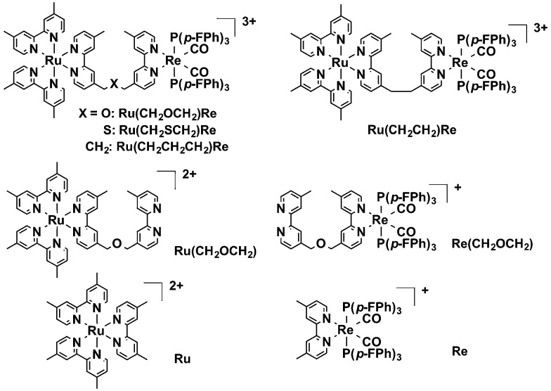
We have developed supramolecular photocatalysts with a Ru(ii) photosensitizer and a Re(i) catalyst connected to each other via a bridging ligand consisting of two diimine moieties connected with an alkyl chain,8e.g., Ru(CH2CH2)Re (Chart 1): the quantum yield (ΦCO) and the turnover number (TONCO) of CO formation were 0.15 and 207, respectively, by using 1-benzyl-1,4-dihydronicotinamide (BNAH) as a reductant,8e which has been the most efficient supramolecular photocatalyst for CO2 reduction of those reported.8b The efficiency and durability of these diad photocatalysts are much higher than those of the corresponding mixed systems. However, these systems still have a problem; the low oxidation power of the excited Ru unit of the diads severely limits the kinds of reductants that can be used. For example, only 62% of the excited Ru units of Ru(CH2CH2)Re were reductively quenched by a relatively high concentration (0.1 M) of BNAH, which has been often used as a sacrificial electron donor. This result means that 38% of the absorbed photons are wasted in the first process of the photocatalytic reaction and cannot be used for CO2 reduction. Therefore, improvement of the oxidation power of the excited Ru unit is required to enhance the photocatalytic activity of the diad. One method for improving the oxidation ability of the excited Ru unit has been reported: introducing electron-withdrawing groups, e.g., –CF3, into the peripheral ligands.8a Although greater efficiency of the quench by a reductant could be achieved, the photocatalytic ability of the diad with such a Ru unit for CO2 reduction was much lower than that of the corresponding diad without the electron-withdrawing groups in the Ru unit. Electron transfer from the reduced Ru unit to the Re unit could not efficiently proceed because the added electron was localized in the peripheral ligands with the electron-withdrawing groups and the redox potential of the Ru unit became more positive than that of the Re unit. Improving the photocatalytic activity of the supramolecular photocatalyst therefore requires both strengthening the oxidation power of the photosensitizer unit and achieving efficient electron transfer from the reduced photosensitizer unit to the catalyst unit.
Chart 1. Structures and abbreviations of the metal complexes.
Recently, we also reported a new hybrid CO2 reduction photocatalyst in which a supramolecular photocatalyst with phosphate anchor groups was adsorbed onto the semiconductor photocatalyst TaON.9 This hybrid photocatalyst exhibited both strong oxidation power and selective reduction power for CO2 reduction because of the Z-scheme mechanism, in which stepwise two-photon excitation can make both a hole as a powerful oxidant in the valence band of TaON and an electron in the photosensitizer unit of the diad. One of the most important keys to improving the efficiency of this promising hybrid photocatalyst is the reconciliation of the stronger oxidation power of the excited photosensitizer unit and the efficient intramolecular electron transfer in the diad because efficient interfacial electron transfer should proceed from the conduction band of TaON to the excited photosensitizer unit of the diad and then to the catalyst unit during the photocatalytic reduction of CO2.
In this report, new Ru(ii)–Re(i) diads with bridging ligands constructed of two diimines connected by –CH2OCH2– or –CH2SCH2– were synthesized and investigated as photocatalysts with enhanced oxidation power; their enhanced oxidation power stems from the greater electronegativity of the bridging ligands' oxygen and sulfur atoms compared to that of the central carbon atom in the alkyl chains such as –CH2CH2CH2– (Chart 1). The diad with the –CH2OCH2– chain exhibited the best performance as a supramolecular catalyst for CO2 reduction using BNAH as the reductant. A detailed mechanism of CO2 reduction using the Ru–Re diads is also reported for the first time.
Results and discussion
The diads were synthesized by the following method: the reaction of [(dmb)2RuCl2]2+ (dmb = 4,4′-dimethyl-2,2′-bipyridine) and the bridging ligand gave Ru(CH2XCH2) (X = O, S, CH2) with a bridging ligand with a non-coordinated diimine moiety; Ru(CH2XCH2) was subsequently reacted with [Re(CO)3{P(p-FPh)3}2(OTf)] to give Ru(CH2XCH2)Re in 8–32% yield calculated on the basis of the amount of [(dmb)2RuCl2]2+ used.
Fig. 1a shows the UV-vis absorption spectra of Ru(CH2OCH2)Re and its model mononuclear complexes (Ru(CH2OCH2) and Re(CH2OCH2)), and Fig. 1b shows those of Ru(CH2CH2CH2)Re and its models (Ru and Re). The spectra of both diads are approximately consistent with the summation spectra of their model complexes, as shown by the dotted lines in the figures. The results indicate that no strong electronic interaction occurs between the Ru and Re units in the ground states of both diads. The broad absorption at 400–550 nm is assignable to metal-to-ligand charge-transfer (1MLCT) absorption of the Ru unit, whereas that at 350–460 nm is attributable to 1MLCT absorption of both Ru and Re units. The strong absorption band at approximately 300 nm is attributed to π–π* absorption of the diimine ligands of both the Ru and the Re units.
Fig. 1. UV-vis absorption spectra of (a) Ru(CH2OCH2)Re (red), Ru(CH2OCH2) (purple), and Re(CH2OCH2) (pink), and (b) Ru(CH2CH2CH2)Re (black), Ru (green), and Re (red). The dotted lines show the 1 : 1 summation spectrum of (a) Ru(CH2OCH2) and Re(CH2OCH2) and (b) Ru and Re. Dimethylformamide (DMF) was used as the solvent.
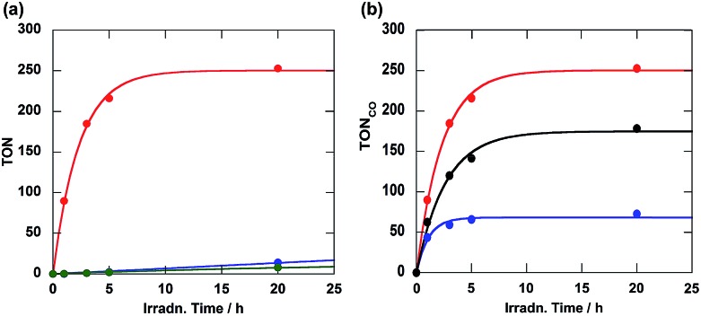
As a typical example of a photocatalytic reaction, a DMF–triethanolamine (TEOA) (5 : 1, v/v) solution containing Ru(CH2OCH2)Re (0.05 mM) and BNAH (0.1 M) as the reductant was irradiated under a CO2 atmosphere at wavelengths greater than 500 nm; these wavelengths could be absorbed only by the Ru unit. Carbon monoxide was selectively produced along with very small amounts of H2 and HCOOH (Fig. 2a). The turnover number of CO formation (TONCO) was as high as 253 for 20 h of irradiation. The quantum yield of CO formation (ΦCO) was 0.18, which was determined using monochromic light at λ = 480 nm (light intensity: 4.3 × 10⁻⁹ einstein s–1). Notably, this ΦCO achieved with Ru(CH2OCH2)Re is the highest value among the reported photocatalytic systems in which BNAH was used as the reductant. The other diads also gave CO selectively; the CO formation achieved using each diad is compared in Fig. 2b. The photocatalytic activity of Ru(CH2OCH2)Re (ΦCO = 0.18, TONCO = 253) was greater than that of Ru(CH2CH2CH2)Re (ΦCO = 0.10, TONCO = 178); however, both the efficiency and stability of Ru(CH2SCH2)Re (ΦCO = 0.09, TONCO = 73) were lower than those of Ru(CH2CH2CH2)Re.
Fig. 2. (a) Turnover number of Ru(CH2OCH2)Re for CO (red), HCOOH (green), and H2 (blue) formation and (b) those of Ru(CH2OCH2)Re (red), Ru(CH2SCH2)Re (black), and Ru(CH2CH2CH2)Re (blue) for CO formation as a function of irradiation time. DMF–TEOA (5 : 1) solutions containing 0.05 mM of the diad and 0.1 M of BNAH were irradiated at λ > 500 nm under a CO2 atmosphere.
Fig. 3 shows the emission spectra of the diads. In all cases, broad emission from the 3MLCT excited state of the Ru unit was observed. The emission maxima of both Ru(CH2OCH2)Re and Ru(CH2SCH2)Re were red-shifted by 10 nm compared to that of Ru(CH2CH2CH2)Re. The emission quantum yields (Φem) and emission lifetimes (τem) of Ru(CH2OCH2)Re and Ru(CH2SCH2)Re decreased compared to those of Ru(CH2CH2CH2)Re according to the energy-gap law (Table 1). These emission properties of the Ru units in both Ru(CH2OCH2)Re and Ru(CH2CH2CH2)Re were very similar to those of their model mononuclear complexes, i.e., Ru(CH2OCH2) and Ru, respectively (Table 1). These similarities strongly suggest that the difference between the emission properties of Ru(CH2OCH2)Re and Ru(CH2CH2CH2)Re was mainly caused by the introduction of the oxygen atom into the bridging ligand; thus, introduction of the Re unit into the opposite side did not strongly affect the emission properties in either case. This result also suggests that intramolecular quenching of the 3MLCT of the Ru unit by electron and/or energy transfer to the Re unit did not proceed or proceeded with very low efficiency.
Fig. 3. The emission spectra of Ru(CH2OCH2)Re (red), Ru(CH2SCH2)Re (blue), and Ru(CH2CH2CH2)Re (black) collected at 25 °C in DMF; the spectra are normalized to the absorbance of the solutions at λexcitation = 456 nm.
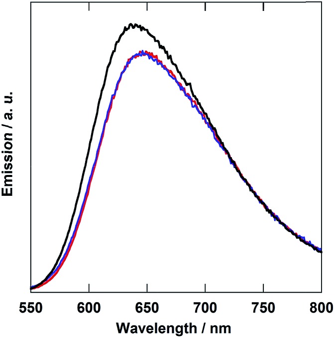
Table 1. Emission properties of the metal complexes and quenching rates of the emission by BNAH a .
| Complex | λ em a /nm | Φ em a | τ em a /ns | k q τ b , c /M–1 s–1 | k q/107 M–1 | η q d |
| Ru(CH2OCH2)Re | 649 | 0.087 | 735 | 42.1 | 5.73 | 0.82 |
| Ru(CH2SCH2)Re | 649 | 0.087 | 734 | 36.3 | 4.95 | 0.78 |
| Ru(CH2CH2CH2)Re | 639 | 0.097 | 761 | 21.0 | 2.76 | 0.67 |
| Ru(CH2OCH2)Re(CO)3(X) | 645 | 0.119 b | 724 b | 14.0 | 1.92 | 0.58 |
| X = –OC(O)OC2H4N(C2H4OH)2 | ||||||
| Ru | 639 | 0.086 | 760 | — | — | — |
| Ru(CH2OCH2) | 649 | 0.092 | 747 | — | — | — |
aDMF was used as the solvent, and the excitation wavelength was 456 nm.
bDMF–TEOA (5 : 1 v/v) was used as the solvent.
cThe excitation wavelength was 520 nm.
dQuenching fraction with 0.1 M BNAH, ηq = 1 – 1/(1 + kqτ[BNAH]).
Emission from the Ru units in all of the diads was reductively quenched by BNAH, and the Stern–Volmer plots of the emission quenching exhibited good linearity (Fig. S1, ESI†). Table 1 summarizes the quenching rate constants of the emission from the Ru units (kq) and the quenching fractions with 0.1 M BNAH (ηq). Under the photocatalytic reaction conditions, the ηq values of Ru(CH2OCH2)Re and Ru(CH2SCH2)Re were approximately 10% higher than that of Ru(CH2CH2CH2)Re. This result strongly suggests that the oxidizing powers of the excited Ru units in Ru(CH2OCH2)Re and Ru(CH2SCH2)Re were improved compared with that of the excited Ru units in Ru(CH2CH2CH2)Re, likely because of the high electronegativities of the heteroatoms introduced into the bridging ligands. The increased quenching fraction should be partly responsible for improving the photocatalytic activity of Ru(CH2OCH2)Re. However, the quenching fraction of Ru(CH2OCH2)Re increased only 1.2-fold compared with that of Ru(CH2CH2CH2)Re, whereas the quantum yield of CO formation in the case of Ru(CH2OCH2)Re increased by 1.7 times compared with that in the case of Ru(CH2CH2CH2)Re. Other factors likely contribute to the improvement of the photocatalytic activity of Ru(CH2OCH2)Re. In addition, both the ΦCO and TONCO in the case of Ru(CH2SCH2)Re were lower compared to those in the case of Ru(CH2CH2CH2)Re, even though the ηq of Ru(CH2SCH2)Re was greater than that of Ru(CH2CH2CH2)Re.
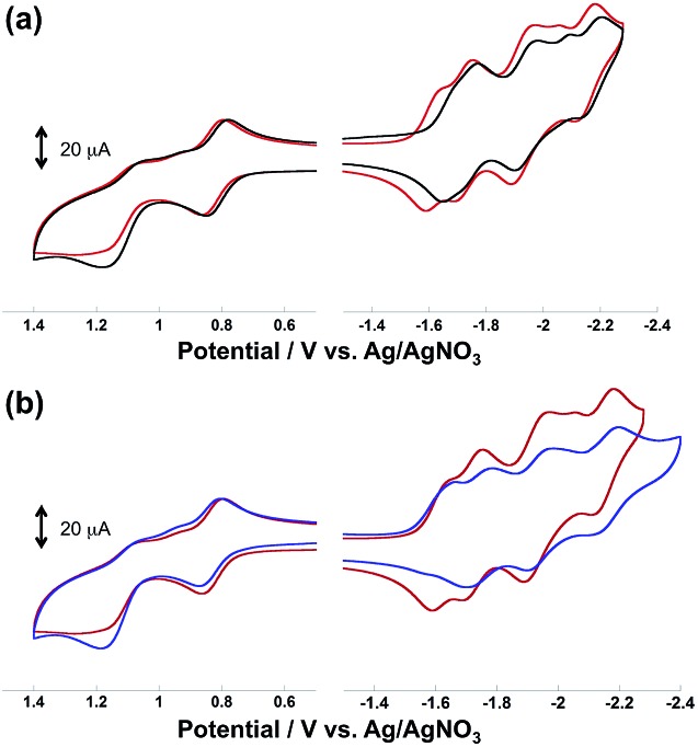
Fig. 4 illustrates the cyclic voltammograms (CVs) of the diads measured in MeCN containing Et4NBF4 (0.1 M) as a supporting electrolyte. In the case of Ru(CH2OCH2)Re, as shown in Fig. 5a, five reduction waves were observed in the cathodic scan; these waves were respectively attributed, from left to right, to the ligand-based reduction of the Re unit, the first ligand-based reduction of the Ru unit, the second ligand-based reduction of the Ru unit, the Re-centered reduction, and the third ligand-based reduction of the Ru unit on the basis of comparison with the corresponding model complexes. All of the reduction waves except for the Re-centered reduction were reversible. In the anodic scan, two oxidation waves were observed, the reversible wave at E1/2 = 0.82 V and the irreversible wave at Ep = 1.21 V were attributed to the Ru-centered (Ru(ii)/Ru(iii)) and the Re-centered oxidation (Re(i)/Re(ii)), respectively.
Fig. 4. Cyclic voltammograms of (a) Ru(CH2OCH2)Re (red) and Ru(CH2CH2CH2)Re (black), and (b) Ru(CH2SCH2)Re (blue) and Ru(CH2OCH2)Re (red) measured in MeCN containing Et4NBF4 (0.1 M) as the supporting electrolyte.
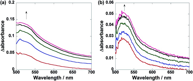
Fig. 5. In situ differential UV-vis absorption spectra of the reaction solutions before and after irradiation: (a) Ru(CH2OCH2)Re, where the irradiation time was 840–1080 s at intervals of 60 s; (b) Ru(CH2CH2CH2)Re, where the irradiation time was 2640–2760 s at intervals of 30 s. DMF–TEOA (5 : 1) solutions containing BNAH (0.1 M) and the complex (0.3 mM) were irradiated under a CO2 atmosphere at λ = 480 nm with a light intensity of 3.2 × 10⁻⁹ einsteins–1.
All redox waves in the CV of Ru(CH2CH2CH2)Re were similarly observed but negatively shifted compared to those of Ru(CH2OCH2)Re (Fig. 4a). In the case of Ru(CH2SCH2)Re, however, the ligand-based reduction of the Re unit was irreversible and the Re-centered reduction wave could not be identified (Fig. 4b). This result suggests that the one-electron-reduced species (OERs) of Ru(CH2SCH2)Re was less stable than the corresponding OERs of the other diads. The first reduction waves of the Re units in both Ru(CH2OCH2)Re and Ru(CH2CH2CH2)Re were observed at potentials similar to those of the corresponding model complexes, i.e., Re(CH2OCH2) and Re (Table 2). This observation also indicates that the Ru unit did not exert a strong electronic effect on the Re units through the bridging ligand. Therefore, the positive shifts of the redox potentials of Ru(CH2OCH2)Re compared to those of Ru(CH2CH2CH2)Re, as described above, are attributable mainly to the electron-withdrawing ability of the oxygen atom in the bridging ligand, which lowers the HOMO and LUMO energies of the Ru and Re units.
Table 2. Electrochemical properties of the metal complexes.
| Complex |
E
1/2 (ΔE/mV)/V vs. Ag/AgNO3 |
||||||
| Ligand based reduction of the Ru unit |
[Re(L/L–)] | [Re0/I] a | [RuII/III] | [ReI/II] a | |||
| Ru(CH2OCH2)Re | –1.73 (61) | –1.93 (103) | –2.15 (76) | –1.62 (66) | –2.00 | +0.82 (70) | +1.21 |
| Ru(CH2SCH2)Re | –1.73 (110) | –1.94 (100) | –2.15 (110) | –1.67 a | — b | +0.84 (70) | +1.19 |
| Ru(CH2CH2CH2)Re | –1.76 (50) | –1.94 (90) | –2.16 (92) | –1.67 (40) | –2.10 | +0.81 (70) | +1.15 |
| Ru(CH2OCH2) | –1.72 (73) | –1.91 (72) | –2.15 (70) | +0.84 (76) | |||
| Ru c | –1.74 (76) | –1.93 (71) | –2.16 (71) | +0.82 (67) | |||
| Re(CH2OCH2) | –1.62 (60) | –2.12 | +1.15 | ||||
| Re c | –1.67 (65) | –2.22 | +1.15 | ||||
The first reduction of Ru(CH2OCH2) was observed at a potential 20 mV more positive than that of Ru; however, the first reduction of Re(CH2OCH2) was 50 mV more positive than that of Re (Table 2). This discrepancy indicates that the introduction of an oxygen atom into the bridging ligand more strongly affected the LUMO energy of the Re unit than that of the Ru unit and that, in the case of Ru(CH2OCH2)Re, the driving force of intramolecular electron transfer from the OERs of the Ru unit to the Re unit was greater than that of Ru(CH2CH2CH2)Re.
These results are consistent with the differences between the UV-vis absorption spectra of the solutions during the photocatalytic reactions in the presence of Ru(CH2OCH2)Re and Ru(CH2CH2CH2)Re (Fig. 5). In the case of Ru(CH2CH2CH2)Re, a relatively sharp absorption band with a maximum at 520 nm appeared during irradiation (Fig. 5a). The corresponding absorption band of Ru(CH2OCH2)Re was broader, with relatively stronger absorption at wavelengths longer than ∼560 nm (Fig. 5b). Both spectra were fitted by a linear combination of the absorption spectra of the OERs of Ru and Re, which were obtained by the flow electrolysis method (Fig. S2, ESI†). Using these data, we calculated the ratios of the OERs between the Ru and Re units to be 1 : 1.3 in the case of Ru(CH2CH2CH2)Re, and 1 : 9.3 in the case of Ru(CH2OCH2)Re (Fig. S3, ESI†). These results strongly indicate that the added electron was more localized on the Re unit in the OERs of Ru(CH2OCH2)Re than that of Ru(CH2CH2CH2)Re because of the greater driving force of the intramolecular electron transfer from the Ru unit to the Re unit. This greater driving force should be another reason for the higher photocatalytic efficiency of Ru(CH2OCH2)Re.
Fig. 6 illustrates size-exclusion chromatograms of the reaction solution in the case of Ru(CH2OCH2)Re. Before irradiation, only a single peak attributed to Ru(CH2OCH2)Re was observed at 34.9 min. The irradiation induced a decrease in the intensity of the peak of Ru(CH2OCH2)Re with the appearance of a new peak at 36.1 min; after 120 min of irradiation, a photostationary state, where the ratio of the peak areas was approximately 3 : 1, was observed. The electrospray ionization (ESI) mass spectra of the eluents collected at 36.1 min showed a peak attributable to [(dmb)2Ru(CH2OCH2)Re(CO)3(CH3COO–)]2+, whose CH3COO– group likely originated from the eluent (MeCN–MeOH (1 : 1 v/v) containing 0.05 M CH3COONH4) at m/z = 591 (Fig. S4, ESI†). This result strongly suggests that the Re unit in some Ru(CH2OCH2)Re complexes was converted into a tricarbonyl complex, i.e., fac-[Re(N⁁N)(CO)3(L)] (N⁁N = diimine ligand, L = monodentate ligand), during the first stage of the photocatalytic reaction.
Fig. 6. Size exclusion chromatograms of the solutions before and after the photocatalytic reaction using Ru(CH2OCH2)Re (irradiation times: 0, 80, 120, 160, and 200 min). The eluent was MeCN–MeOH (1 : 1 v/v) containing 0.5 M CH3COONH4; two Shodex PROTEIN KW402.5 columns were used with a KW-LG guard column under the following conditions: flow rate, 0.2 mL min–1; column temperature, 40 °C; detection wavelength, 390 nm. The reaction conditions were the same as those described in Fig. 5.

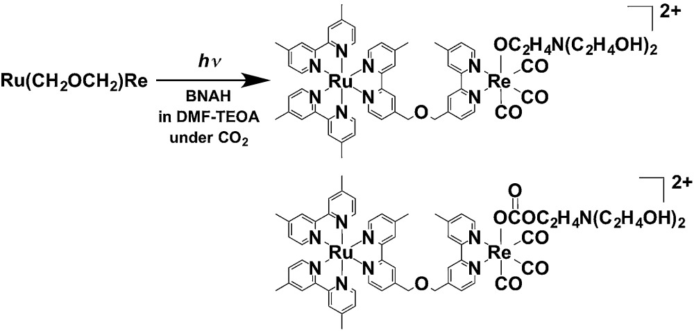
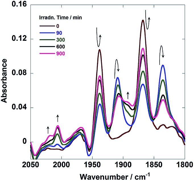
Fig. 7 shows in situ IR spectral changes of a solution during the photocatalytic reaction. The concentration of the diad was greater than that used in the case of Fig. 6 because of the lower sensitivity of the IR spectrometer compared to that of the size exclusion chromatograph. Immediately after the irradiation was initiated, the CO-stretching bands corresponding to the Re unit of Ru(CH2OCH2)Re (νCO = 1938 and 1868 cm–1) decreased in intensity, whereas a pair of bands of the corresponding OERs (νCO = 1909 and 1836 cm–1) increased in intensity.10 Further irradiation resulted in the formation of new bands attributable to two kinds of diads with a Re tricarbonyl unit (νCO = 2018, 2006, and ∼1890 cm–1; other νCO bands associated with these species should be observed, but they were overlapped by the bands of other species). These species were identified as diads with two types of the Re units: fac-[Re(N⁁N)(CO)3{OC2H4N(C2H4OH)2}] with a deprotonated TEOA ligand, and its CO2-inserted product, fac-[Re(N⁁N)(CO)3{OC(O)OC2H4N(C2H4OH)2}], where both TEOA and CO2 molecules are captured to form a carbonate ester ligand. These structural assignments are based on the similarities of these species to the corresponding Re mononuclear complexes, i.e., fac-[Re(bpy)(CO)3{OC2H4N(C2H4OH)2}] (νCO = 2006, 1897, 1881 cm–1) and fac-[Re(bpy)(CO)3{OC(O)OC2H4N(C2H4OH)2}] (νCO = 2020, 1915, 1892 cm–1) (bpy = 2,2′-bipyridine), reported in our previous paper.11 As described below, the IR spectra of authentic samples of the diads with either a –OC2H4N(C2H4OH)2 or a –OC(O)OC2H4N(C2H4OH)2 ligand, i.e., Ru(CH2OCH2)Re(CO)3(X) (X = –OC2H4N(C2H4OH)2 or –OC(O)OC2H4N(C2H4OH)2) also showed similar CO-stretching bands (Fig. S5, ESI†). These results strongly indicate that Ru(CH2OCH2)Re was partially converted into Ru(CH2OCH2)Re(CO)3(X) in the first stage of the photocatalytic reaction (eqn (1)).
 |
1 |
Fig. 7. In situ IR spectra of a DMF–TEOA (5 : 1 v/v) solution containing Ru(CH2OCH2)Re (1 mM) and BNAH (0.1 M) during photoirradiation at λ = 480 nm under a CO2 atmosphere.
Further irradiation resulted in a photostationary state, where the reaction solution contained both Ru(CH2OCH2)Re and Ru(CH2OCH2)Re(CO)3(X) in an approximately 3 : 1 ratio, as described above. Fig. 8 illustrates the initial stage of photocatalytic CO formation at lower light intensity (3.2 × 10⁻⁹ einstein s–1) than that used in the case of Fig. 2. An induction period of CO formation was observed in the case of Ru(CH2OCH2)Re, which strongly indicates that Ru(CH2OCH2)Re(CO)3(X) played an important role in the photocatalytic reaction. Therefore, we synthesized Ru(CH2OCH2)Re(CO)3(X) by reacting Ru(CH2OCH2)Re(CO)3(MeCN), TEOA, and CO211 and investigated the photocatalytic ability of Ru(CH2OCH2)Re(CO)3(X); the results are also shown in Fig. 8 (green). The clear induction period of CO formation disappeared; however, the quantum yield of CO formation (ΦCO = 0.12) was lower than that achieved with Ru(CH2OCH2)Re (ΦCO = 0.18, red in Fig. 8). Given these results, we examined the photocatalytic ability of a 3 : 1 mixed system of Ru(CH2OCH2)Re and Ru(CH2OCH2)Re(CO)3(X), which is a similar ratio observed in the photostationary state when only Ru(CH2OCH2)Re was used as the photocatalyst (Fig. 6). As shown in Fig. 8 (orange), no clear induction period was observed and the quantum yield of CO formation achieved using this system (ΦCO = 0.19) was similar to that achieved using Ru(CH2OCH2)Re after the induction period (ΦCO = 0.18). Therefore, we conclude that Ru(CH2OCH2)Re and Ru(CH2OCH2)Re(CO)3(X) played important but different roles in the photocatalytic reaction.
Fig. 8. Photocatalytic CO formation using DMF-TEOA (5 : 1 v/v) solutions containing 0.1 M of BNAH and 0.3 mM of Ru(CH2OCH2)Re (red), Ru(CH2OCH2)Re(CO)3(X) (green), or a 3 : 1 mixture of Ru(CH2OCH2)Re and Ru(CH2OCH2)Re(CO)3(X) (orange). The reaction conditions were same as those described in Fig. 5.
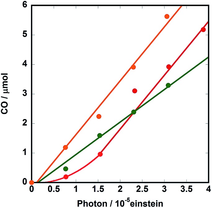
Fig. 9 illustrates the rise and decay curves of the FT-IR absorption peaks (Fig. 7) attributed to each diad in the reaction solution during irradiation. However, immediately after the irradiation was started, the OERs of the Re unit in Ru(CH2OCH2)Re (blue) formed rapidly and its concentration decreased between 120 s and 600 s of irradiation time, the non-reduced Ru(CH2OCH2)Re (red) was recovered. Further irradiation did not induce a change in the ratio between the OERs and non-reduced species. The decrease of the concentration of the OERs appeared to occur after Ru(CH2OCH2)Re(CO)3(X) (green and purple) was accumulated in the reaction solution. These results indicate that efficient electron transfer from the OERs of Ru(CH2OCH2)Re to Ru(CH2OCH2)Re(CO)3(X) and/or an intermediate produced from the OERs of Ru(CH2OCH2)Re(CO)3(X) occurred during the steady-state CO formation in the photocatalytic reaction.
Fig. 9. Changes in the intensities of the absorbance peaks in the in situ IR spectra (Fig. 7): Ru(CH2OCH2)Re(CO)3(X) (green, 2018 cm–1, X = –OC(O)OC2H4N(C2H4OH)2; purple, 2006 cm–1, X = –OC2H4N(C2H4OH)2), Ru(CH2OCH2)Re (red, 1938 cm–1), and the OER species of Ru(CH2OCH2)Re (blue, 1909 cm–1). See Fig. 7.
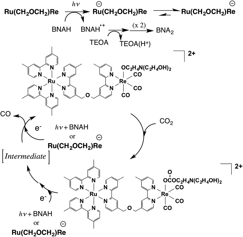
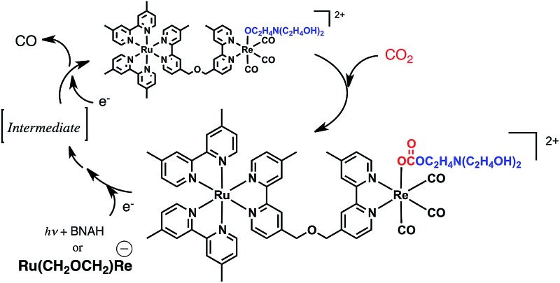
Scheme 1 summarizes the possible mechanism for the photocatalytic reaction involving Ru(CH2OCH2)Re. The Ru unit is selectively excited, and the resulting 3MLCT excited state is reductively quenched by BNAH to give the OER species of the Ru unit of Ru(CH2OCH2)Re. Rapid intramolecular electron transfer proceeds from the OERs of the Ru unit to the Re unit to give the OER species of the Re unit of Ru(CH2OCH2)Re. Rapid abstraction of a proton from the one-electron-oxidized BNAH by TEOA and dimerization have been reported to proceed to give BNA2. In the first stage of the photocatalytic reaction, approximately a quarter of the added Ru(CH2OCH2)Re was efficiently converted into Ru(CH2OCH2)Re(CO)3(X) (X = –OC2H4N(C2H4OH)2 or –OC(O)OC2H4N(C2H4OH)2), which was the real photocatalyst for CO2 reduction. Ru(CH2OCH2)Re, which remained in the solution, functioned as a redox photosensitizer that supplied electrons to Ru(CH2OCH2)Re(CO)3(X) and/or the intermediate during the photocatalytic reaction. Notably, the Ru unit of Ru(CH2OCH2)Re(CO)3(X) should serve as another redox photosensitizer (Table 1, Fig. S6, ESI†) because Ru(CH2OCH2)Re(CO)3(X) alone can function as a relatively efficient photocatalyst for CO2 reduction, though its ΦCO is lower than that of the mixed system. Because the absorption band attributable to the OER species of Ru(CH2OCH2)Re(CO)3(X) was not detected in the UV-vis absorption spectrum of the reaction solution during the photocatalytic reaction, the photochemically accepted electron in the Ru unit should rapidly transfer to the Re unit and then participate in the reduction of CO2. The electrons for the second reduction process, where an electron was accepted by the Re unit of the intermediate forming from the OER species of Ru(CH2OCH2)Re(CO)3(X) to produce CO, originated from two possible sources: the reduced Ru unit in the intermediate or the reduced Ru(CH2OCH2)Re. The previously described results indicate that the reduction efficiency with the latter species was better than that with the former species; i.e., the reduction of the intermediate should be a rate-limiting process in the photocatalytic reduction of CO2viaRu(CH2OCH2)Re(CO)3(X) under the investigated reaction conditions. Because similar photocatalytic behavior of Ru(CH2CH2CH2)Re was observed (Fig. S7–S9, ESI†), the photocatalytic reaction involving Ru(CH2CH2CH2)Re should proceed through a mechanism similar to that for Ru(CH2OCH2)Re.
Scheme 1. Partial reaction mechanism of photocatalytic CO2 reduction by Ru(CH2OCH2)Re.
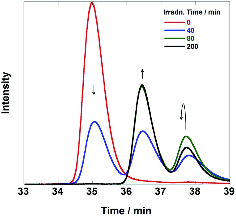
As previously described, the durability of Ru(CH2SCH2)Re was much lower than that observed for the other diads. Fig. 10 shows SEC analysis data of the reaction solution; these chromatograms clearly indicate that Ru(CH2SCH2)Re completely disappeared after irradiation for 80 min and that two new species with smaller sizes formed. The LC-MS analysis data (Fig. S10, ESI†) indicated that the species detected at retention times of 36.5 min and 37.8 min were Ru(ii) mononuclear complexes, i.e., Ru(CH2OCH2), Ru, and [Ru(dmb)2(CS–)]+ (CS– = MebpyCH2S–), and Re(i) mononuclear complexes, i.e., Re, [Re(CH2OCH2)(CO)2{P(p-FPh3)2}2]+, and [Re(dmb) (CO)2{P(p-FPh)3}(MeCN)]+ (MeCN was contained in the eluent), respectively. Therefore, Ru(CH2SCH2)Re was completely cleaved to give the mononuclear complexes in the first stage of the reaction, which should lower both the efficiency and durability of the photocatalysis of Ru(CH2SCH2)Re.
Fig. 10. Size exclusion chromatograms of the solutions before and after the photocatalytic reaction using Ru(CH2SCH2)Re (irradiation times: 0, 40, 80, and 200 min). The reaction and analytical conditions were the same as those described in Fig. 6.
Experimental
General procedures
UV-vis absorption spectra were recorded on a JASCO V-565 spectrophotometer. 1H NMR spectra were recorded on a JEOL AL300 (300 MHz) spectrometer. The residual proton of the deuterated solvent (acetone-d6 or acetonitrile-d3) was used as an internal standard. Emission spectra were measured at 25 ± 0.1 °C under an Ar atmosphere using a JASCO FP-6500 spectrofluorometer. Emission quantum yields were obtained with a Hamamatsu photonics C-9920-02 integrating sphere and a multi-photodiode-array detector. Emission lifetimes were measured with a Horiba FluoroCube time-correlated single-photon counting system (the excitation source was an LED pulse lamp (456 nm) with an instrumental response time of less than 0.1 ns). In the quenching experiments, the changes in the emission intensities of solutions containing a complex were monitored in the presence of various amounts of the quencher, BNAH. Quenching rate constants (kq) were calculated from linear Stern–Volmer plots. Electrospray ionization-mass spectroscopy (ESI-MS) was recorded on a Shimadzu LCMS-2010A mass spectrometer using MeCN or MeOH as the mobile phase. The redox potentials of the complexes in a MeCN solution were measured using a cyclic voltammetric technique. The CVs were recorded on an ALS/CHI CHI-620 electrochemical analyzer using Et4NBF4 (0.1 M) as the supporting electrolyte, a glassy-carbon disk working electrode (3 mm diameter), an Ag/AgNO3 (0.01 M) reference electrode, and a Pt counter electrode. The scan rate was 200 mV s–1. Analytical SEC12 was conducted using an HPLC system consisting of a JASCO 880-PU pump, a pair of Shodex PROTEIN KW402.5 columns, a KW-LG guard column, a Rheodyne 7125 injector, and a JASCO MD-2010 plus UV-Vis photodiode-array detector. The column temperature was maintained at 40 °C using a JASCO 860-CO column oven. A mixed solution of MeCN–MeOH (1 : 1 v/v) containing CH3COONH4 (0.5 mM) was used as the mobile phase. In the case of HPLC(SEC)-MS analyses, a HPLC system consisting of the SEC columns and the guard column, a Rheodyne 7125 injector, a Shimadzu FCV-10ALVP gradient unit, and a Shimadzu LC-10ADVP pump was connected before the ESI-MS detector. The column temperature was maintained at 40 °C using a Shimadzu SPD CTO-10ACVP oven. A MeCN–MeOH (1 : 1 v/v) mixed solution containing CH3COONH4 (0.05 mM) was used as the mobile phase. Isolation of the diads was achieved by preparative SEC using a pair of Shodex PROTEIN KW 2002.5 columns, a KW-LG guard column, and a JAI LC-9201 recycling preparative HPLC apparatus with a JASCO 870-UV detector. A MeCN–MeOH (1 : 1 v/v) mixed solution containing CH3COONH4 (0.15 mM) was used as the mobile phase.
Photocatalytic reactions
Photocatalytic reactions were performed on a 4 mL DMF–TEOA (5 : 1 v/v) mixed solution containing the diad (0.05 mM) and BNAH (0.1 M) in an 11 mL test tube (i.d. 8 mm). After the solution was purged with CO2 for 15 min, it was irradiated in a merry-go-round irradiation apparatus using λ > 500 nm light from a high-pressure Hg lamp equipped with a uranyl glass and a K2CrO4 (30% w/w, light pass length: 1 cm) solution filter. The tube was cooled with tap water during irradiation. In the case of quantum yield measurements, the mixed solution containing a higher concentration of the diad (0.3 mM) in a quartz cubic cell (the light pass length: 1 cm) was irradiated using a 480 nm monochromic light from an Ushio UXL-500D-O xenon short-arc lamp equipped with a 480 nm (FWHM: 10 nm) band-pass filter (Asahi Spectra Co.) and a CuSO4 solution filter (250 g L–1, light pass length: 5 cm). The absorbance of the reaction solution (>3 at 480 nm) during the measurement indicated that most of the irradiated light was absorbed by the diad in the solution. The temperature of the solutions was controlled during irradiation at 25 ± 0.1 °C using an IWAKI CTS-134A constant-temperature system. The incident light intensity was determined using a K3Fe(C2O4)3 actinometer.13 The gaseous products, i.e., CO and H2, were analyzed by GC-TCD (GL Science GC323), and the liquid-phase product, i.e., HCOOH, was analyzed by a capillary electrophoresis system (Otsuka Electronics Co. Capi-33001).
Materials
Acetonitrile was distilled over P2O5 three times and then distilled over CaH2 immediately before use. DMF was dried over molecular sieves 4A and then distilled under reduced pressure (10–20 mmHg). TEOA was distilled under reduced pressure (<1 mmHg). DMF and TEOA were stored under an Ar atmosphere prior to use. Et4NBF4 was dried under vacuum at 100 °C for a day prior to use. All other reagents were reagent-grade quality and were used without further purification. BNAH,14 the bridging ligands (4′-methyl-[2,2′-bipyridine]-4-yl)-CH2XCH2-(4′-methyl-[2,2′-bipyridine]-4-yl): X = O (CH2OCH2);15 S (CH2SCH2);15 CH2 (CH2CH2CH2),16 Ru(dmb)2Cl2,17 and mer-[Re(CO)3{P(p-FPh3)}2Br]18 were synthesized according to the methods described in the literature.
Synthetic procedures
Synthesis of [Re(CO)2{P(p-FPh)3}2(CH2OCH2)](PF6)·3H2O (Re(CH2OCH2))
A THF solution (17 mL) containing mer-[Re(CO)3{P(p-FPh3)}2Br] (197 mg, 0.200 mmol) and AgOTf (54.0 mg, 0.210 mmol) was refluxed for 3 h under an N2 atmosphere in the absence of light. After the mixture had cooled to room temperature, the white precipitate was removed by filtration through Celite. After evaporation of the solvent, CH2OCH2 (229 mg, 0.599 mmol) was added to the residue and the mixture was dissolved in EtOH (60 mL). The solution was refluxed for 5 h under an N2 atmosphere in the absence of light. After evaporation of the solvent, the by-products were removed by column chromatography on an SP Sephadex C-25 ion-exchange column using MeCN–H2O (1 : 1 v/v) containing NH4PF6 as the eluent and then by preparative SEC. Purification of the product was achieved by recrystallization using a MeOH–H2O mixed solvent. The yield was 32% (91 mg, 0.065 mmol). Elemental analysis calcd (%) for C62H52F12N4O6P3Re: C. 51.14; H. 3.60; N. 3.85, found: C. 51.18; H. 3.50; N. 3.89. 1H-NMR (300 MHz, acetone-d6) δ/ppm: 8.68 (d, J = 4.8 Hz, 1H, β-bpy-6), 8.51 (s, 1H, γ-bpy-3), 8.49 (d, J = 4.4 Hz, 1H, α-bpy-6), 8.41 (s, 1H, β-bpy-3), 8.35 (s, 1H, δ-bpy-3), 8.28 (s, 1H, α-bpy-3), 8.19 (d, J = 4.8 Hz, 1H, γ-bpy-6), 8.07 (d, J = 3.6 Hz, 1H, δ-bpy-6), 7.44 (d, J = 4.8 Hz, 1H, β-bpy-5), 7.38–7.32 (m, 12H, Ph-o), 7.28–7.23 (m, 2H, α-bpy-5, γ-bpy-5), 7.12 (t, JHH = 8.4 Hz, JFH = 8.4 Hz, 12H, Ph-m), 7.07 (d, J = 5.6 Hz, 1H, δ-bpy-5), 4.84 (s, 2H, β-CH2), 4.82 (s, 2H, γ-CH2), 2.46 (s, 6H, α-bpy-CH3, δ-bpy-CH3). FT-IR (in CH2Cl2) νCO/cm–1: 1868, 1939. ESI-MS (eluent: MeCN) m/z: 629 ([M – PF6– + H+]2+), 944 ([M – P(p-FPh)3 – PF6–]+).
Synthesis of [(dmb)2Ru(CH2OCH2)](PF6)2·H2O (Ru(CH2OCH2))
An EtOH–H2O (40 mL and 10 mL) mixed solution containing Ru(dmb)2Cl2 (91.5 mg, 0.159 mmol) and CH2OCH2 (184 mg, 0.482 mmol) was refluxed for 8 h under an N2 atmosphere in the absence of light. After evaporation of the solvent, water was added to the residue, giving a white precipitate of CH2OCH2; this precipitate was removed by filtration. NH4PF6 was added to the filtrate to give precipitates, which were recovered by filtration and washed with H2O. The product was isolated by column chromatography on an SP Sephadex C-25 ion-exchange column using MeCN–H2O (1 : 1 v/v) containing NH4PF6 as the eluent; the product was subsequently recrystallized from a CH2Cl2–ether mixed solvent. The yield was 88% (160 mg, 0.14 mmol). Elemental analysis calcd (%) for C48H48F12N8O2P2Ru: C. 49.70; H. 4.17; N. 9.66, found: C. 49.66; H. 4.13; N. 9.59. 1H-NMR (300 MHz, acetone-d6) δ/ppm: 8.78 (s, 1H, β-bpy-3), 8.66 (s, 5H, dmb-3, α-bpy-3), 8.62 (d, J = 4.5 Hz, 1H, γ-bpy-6), 8.48–8.46 (m, 2H, δ-bpy-6, γ-bpy-3), 8.31 (s, 1H, δ-bpy-3), 7.98 (d, J = 5.7 Hz, 1H, β-bpy-6), 7.85–7.81 (m, 5H, α-bpy-6, dmb-6), 7.57 (d, J = 4.2 Hz, 1H, β-bpy-5), 7.42–7.35 (m, 6H, γ-bpy-5, dmb-5, α-bpy-5), 7.25 (d, J = 4.8 Hz, 1H, δ-bpy-5), 4.92 (s, 2H, β-CH2), 4.85 (s, 2H, γ-CH2), 2.55–2.43 (m, 18H, dmb-CH3, α-bpy-CH3, δ-bpy-CH3). ESI-MS (eluent: MeCN) m/z: 426 ([M – 2PF6–]2+).
The other mononuclear complexes (Ru(CH2SCH2) and Ru(CH2CH2CH2)) were synthesized in a manner similar to that used for Ru(CH2OCH2) but with CH2SCH2 or CH2CH2CH2 used instead of CH2OCH2 as the bridging ligand.
[(dmb)2Ru(CH2SCH2)](PF6)2 (Ru(CH2SCH2))
Yield 44%. 1H-NMR (300 MHz, acetone-d6) δ/ppm: 8.60 (s, 4H, dmb-3), 8.47 (s, 1H, β-bpy-3), 8.36 (d, J = 5.2 Hz, 1H, γ-bpy-6), 8.34 (s, 1H, γ-bpy-3), 8.29 (d, J = 4.9 Hz, 1H, δ-bpy-6), 8.26 (s, 1H, α-bpy-3), 8.11 (s, 1H, δ-bpy-3), 7.81 (d, J = 5.9 Hz, 1H, β-bpy-6), 7.76–7.71 (m, 5H, dmb-6, α-bpy-6), 7.46 (d, J = 5.9 Hz, 1H, β-bpy-5), 7.41–7.25 (m, 6H, α-bpy-5, dmb-5, γ-bpy-5), 7.17 (d, J = 4.2 Hz, 1H, δ-bpy-5), 3.94–3.78 (m, 4H, β-CH2, γ-CH2), 2.53–2.33 (m, 18H, dmb-CH3, α-bpy-CH3, δ-bpy-CH3). ESI-MS (eluent: MeCN) m/z: 434 ([M – 2PF6–]2+).
[(dmb)2Ru(CH2CH2CH2)](PF6)2 (Ru(CH2CH2CH2))
Yield 34%. 1H-NMR (300 MHz, acetone-d6) δ/ppm: 8.67 (s, 1H, β-bpy-3), 8.64 (s, 4H, dmb-3), 8.62 (s, 1H, α-bpy-3), 8.52 (d, J = 5.0 Hz, 1H, γ-bpy-6), 8.47 (d, J = 5.0 Hz, 1H, δ-bpy-6), 8.29 (s, 2H, γ-bpy-3, δ-bpy-3), 7.86–7.80 (m, 6H, α-bpy-6, β-bpy-6, dmb-6), 7.45 (d, J = 5.5 Hz, 1H, β-bpy-5), 7.38–7.36 (m, 5H, α-bpy-5, dmb-5), 7.29–7.25 (m, 2H, γ-bpy-5, δ-bpy-5), 3.00–2.81 (m, 4H, β-CH2, γ-CH2), 2.55–2.43 (m, 18H, dmb-CH3, α-bpy-CH3, δ-bpy-CH3), 2.16 (tt, 4H, J = 4.6 Hz, 4.6 Hz, –CH2–CH2–CH2–). ESI-MS (eluent: MeCN) m/z: 426 ([M – 3PF6–]3+).
[(dmb)2Ru(CH2OCH2)Re{P(p-FPh)3}2](PF6)3 (Ru(CH2OCH2)Re)
A THF solution (30 ml) containing mer-[Re(CO)3{P(p-FPh3)}2Br] (86.5 mg, 0.0880 mmol) and AgOTf (23.7 mg, 0.0924 mmol) was refluxed for 4 h under an N2 atmosphere in the absence of light. After the mixture had cooled to room temperature, white precipitates were removed by filtration through Celite. After evaporation of the solvent, Ru(CH2OCH2) (51.4 mg, 0.0450 mmol) was added to the residue, and the mixture was dissolved in EtOH (60 mL). The solution was refluxed for 15 h under an N2 atmosphere in the absence of light. After evaporation of the solvent, the product was purified by column chromatography on a CM Sephadex C-25 ion-exchange column using MeCN–H2O (1 : 1 v/v) containing NH4PF6 as the eluent; the product was subsequently recrystallized with CH2Cl2–ether mixed solvent. The yield was 36% (35 mg, 0.016 mmol). Elemental analysis calcd (%) for C86H70F24N8O3P5ReRu: C. 47.78; H. 3.26; N. 5.18. Found: C. 47.52; H. 3.36; N. 5.16. 1H-NMR (300 MHz, acetone-d6) δ/ppm: 8.72 (s, 1H, β-bpy-3), 8.62 (s, 5H, α-bpy-3, dmb-3), 8.29 (s, 1H, γ-bpy-3), 8.20 (s, 1H, δ-bpy-3), 8.05 (d, J = 5.6 Hz, 1H, γ-bpy-6), 7.93 (d, J = 5.6 Hz, 1H, β-bpy-6), 7.90 (d, J = 5.6 Hz, 1H, δ-bpy-6), 7.81–7.79 (m, 5H, α-bpy-6, dmb-6), 7.55 (d, J = 5.6 Hz, 1H, β-bpy-5), 7.35–7.27 (m, 17H, α-bpy-5, dmb-5, Ph-o), 7.18 (d, J = 5.6 Hz, 1H, γ-bpy-5), 7.06 (dd, JHH = 7.8 Hz, JFH = 7.8 Hz, 12H, Ph-m), 6.97 (d, J = 5.2 Hz, 1H, δ-bpy-5), 4.86 (s, 2H, β-CH2), 4.82 (s, 2H, γ-CH2), 2.54–2.44 (m, 18H, dmb-CH3 α-bpy-CH3, δ-bpy-CH3). FT-IR (in CH2Cl2) νCO/cm–1: 1870, 1940. ESI-MS (eluent: MeCN) m/z: 576 ([M – 3PF6–]3+), 936 ([M – 2PF6–]2+).
The other diad was synthesized in a manner similar to that used to prepare Ru(CH2OCH2)Re but with Ru(CH2SCH2) or Ru(CH2CH2CH2) used instead of Ru(CH2OCH2).
Yield 19%. Elemental analysis calcd (%) for C86H72F24N8O3P5ReRuS: C. 47.04; H. 3.31; N. 5.10; S. 1.46. Found: C. 47.04; H. 3.45; N. 5.09; S. 1.68. 1H-NMR (300 MHz, acetone-d6) δ/ppm: 8.76 (s, 1H, γ-bpy-3), 8.66 (s, 5H, β-bpy-3, dmb-3), 8.33 (s, 1H, δ-bpy-3), 8.26 (s, 1H, α-bpy-3), 8.11 (d, J = 5.6 Hz, 1H, γ-bpy-6), 7.96 (d, J = 5.6 Hz, 1H, β-bpy-6), 7.89–7.81 (m, 6H, α-bpy-6, dmb-6, δ-bpy-6), 7.53 (d, J = 6.0 Hz, 1H, β-bpy-5), 7.39–7.29 (m, 17H, α-bpy-5, dmb-5, Ph-o), 7.17 (d, J = 5.6 Hz, 1H, γ-bpy-5), 7.10 (dd, JHH = 8.6 Hz, JFH = 8.4 Hz, 12H, Ph-m), 6.99 (d, J = 5.6 Hz, 1H, δ-bpy-5), 3.94–3.88 (m, 4H, β-CH2, γ-CH2), 2.57–2.54 (m, 18H, dmb-CH3, α-bpy-CH3, δ-bpy-CH3). FT-IR (in CH2Cl2) νCO/cm–1: 1868, 1939. ESI-MS (eluent: MeCN) m/z: 581 ([M – 3PF6–]3+), 944 ([M – 2PF6–]2+).
[(dmb)2Ru(CH2CH2CH2)Re{P(p-FPh)3}2](PF6)3 (Ru(CH2CH2CH2)Re)
Yield 72%. Elemental analysis calcd (%) for C87H72F24N8O2P5ReRu: C. 48.38; H. 3.36; N. 5.19. Found: C. 48.40; H. 3.45; N. 5.06. 1H-NMR (300 MHz, acetone-d6) δ/ppm: 8.61 (s, 1H, β-bpy-3), 8.59 (s, 5H, α-bpy-3, dmb-3), 8.19 (s, 1H, γ-bpy-3), 8.16 (s, 1H, δ-bpy-3), 7.98 (d, J = 5.3 Hz, 1H, γ-bpy-6), 7.80–7.78 (m, 2H, β-bpy-6, α-bpy-6), 7.74–7.72 (m, 5H, δ-bpy-6, dmb-6), 7.38 (d, J = 6.0 Hz, 1H, β-bpy-5), 7.32–7.25 (m, 17H, α-bpy-5, dmb-5, Ph-o), 7.04 (dd, JHH = 8.6 Hz, JFH = 8.6 Hz, 12H, Ph-m), 6.96 (d, J = 5.6 Hz, 1H, γ-bpy-5), 6.90 (d, J = 5.9 Hz, 1H, δ-bpy-5), 2.86 (s, 2H, β-CH2), 2.78 (s, 2H, γ-CH2), 2.50–2.40 (m, 18H, dmb-CH3 α-bpy-CH3, δ-bpy-CH3), 2.01 (tt, 4H, J = 2.1 Hz, 2.1 Hz, –CH2–CH2–CH2–). FT-IR (in CH2Cl2) νCO/cm–1: 1868, 1938. ESI-MS (eluent: MeCN) m/z: 575 ([M – 3PF6–]3+), 935 ([M – 2PF6–]2+).
Synthesis of [(dmb)2Ru(CH2OCH2)Re(CO)3Br](PF6)2 (Ru(CH2OCH2)Re(CO)3Br)
Ru(CH2OCH2) (68.5 mg, 0.06 mmol) and Re(CO)5Br (32.5 mg, 0.08 mmol) were dissolved in EtOH (60 mL), and the solution was refluxed for 5 h under an N2 atmosphere in the absence of light. After evaporation of the solvent, Ru(CH2OCH2)Re(CO)3Br was isolated by ion-exchange column chromatography on a SP Sephadex C-25 column using acetonitrile–water (1 : 1 v/v) containing NH4PF6 as the eluent. Although a small amount of Ru(CH2OCH2)Re(CO)3(MeCN) byproduct was present as a contaminant, the recovered sample was used in the subsequent synthesis without further purification. Yield: 66.5 mg (crude). FT-IR (in CH2Cl2) νCO/cm–1: 2039, 2022, 1919. ESI-MS (eluent: MeCN) m/z: 600 ([M – 2PF6–]2+).
Synthesis of [(dmb)2Ru(CH2OCH2)Re(CO)3(MeCN)](PF6)3·H2O (Ru(CH2OCH2)Re(CO)3(MeCN))
The crude sample (75.3 mg) of Ru(CH2OCH2)Re(CO)3Br containing Ru(CH2OCH2)Re(CO)3(MeCN) and CF3SO3H (0.03 mL, 0.34 mmol) were dissolved in o-dichlorobenzene (7 mL), and the solution was refluxed for 5 h under an Ar atmosphere in the absence of light. After evaporation of the solvent, the product was isolated by ion-exchange column chromatography on a CM Sephadex C-25 column using MeCN–H2O (1 : 1 v/v) containing NH4PF6 as the eluent. After evaporation of the solvent, Ru(CH2OCH2)Re(CO)3(MeCN) was obtained by recrystallization from a CH2Cl2–diethyl ether mixed solution as a red solid. The yield was 70% (56.5 mg, 0.05 mmol). Elemental analysis calcd (%) for C53H51F18N9O5P3ReRu: C, 39.39; H, 3.18; N, 7.80. Found: C, 39.36; H, 3.19; N, 7.71. 1H-NMR (300 MHz, acetonitrile-d3) δ/ppm: 8.96 (d, J = 5.9 Hz, 1H, β-bpy-6), 8.85 (d, J = 5.7 Hz, 1H, α-bpy-6), 8.47 (s, 1H, β-bpy-3), 8.44 (s, 1H, α-bpy-3), 8.37 (s, 1H, γ-bpy-3), 8.34 (s, 1H, δ-bpy-3), 8.32 (s, 4H, dmb-3), 7.70 (d, J = 5.7 Hz, 1H, γ-bpy-6), 7.68 (d, J = 6.2 Hz, 1H, β-bpy-5), 7.55–7.49 (m, 6H, δ-bpy-6, dmb-6, α-bpy-5), 7.39 (d, J = 5.7 Hz, 1H, γ-bpy-5), 7.21–7.20 (m, 5H, δ-bpy-5, dmb-5), 4.91 (s, 2H, β-CH2), 4.88 (s, 2H, γ-CH2), 2.56–2.51 (m, 18H, dmb-CH3, β-bpy-CH3, γ-bpy-CH3), 2.04 (s, 3H, CH3–CN–). FT-IR (in MeCN) νCO/cm–1: 2039, 1934. ESI-MS (eluent: MeCN) m/z: 600 ([M – MeCN + Br– – 3PF6–]3+), 655 ([M – 2PF6–]2+).
Synthesis of [(dmb)2Ru(CH2OCH2)Re(CO)3(OC(O)OC2H4N(C2H4OH)2)](PF6)2 (Ru(CH2OCH2)Re(CO)3(X))
Ru(CH2OCH2)Re(CO)3(MeCN) was dissolved in DMF, and the resulting solution was stirred overnight. TEOA was added to the solution, and the solution was stirred for an hour to give a mixture of Ru(CH2OCH2)Re(CO)3(DMF) and Ru(CH2OCH2)Re(CO)3(TEOA). Ru(CH2OCH2)Re(CO)3(X) was obtained by bubbling the solution with CO2 for 10 min. The reversibility of this CO2 insertion reaction was confirmed by the recovery of the starting complexes in the solution after bubbling with Ar for 20 min. FT-IR (in MeCN) νCO/cm–1: 2006, 2018 (Fig. S5, ESI†).
Conclusions
The greatest photocatalytic activity for CO2 reduction using BNAH as the reductant was achieved using Ru(CH2OCH2)Re (ΦCO = 0.18, TONCO = 253). Introduction of an oxygen atom into the bridging unit improved the oxidation power of the excited Ru unit in the diad and increased the driving force of the intramolecular electron transfer from the OER species of the Ru unit to the Re unit. During the photocatalytic reaction, a part of the used Ru(CH2OCH2)Re was converted into Ru(CH2OCH2)Re(CO)3(X) (X = –OC2H4N(C2H4OH)2 or –OC(O)OC2H4N(C2H4OH)2) during the initial stage of the photocatalytic reaction. The 3 : 1 mixture of Ru(CH2OCH2)Re and Ru(CH2OCH2)Re(CO)3(X), which respectively functioned as a photosensitizer and a photocatalyst in the photostationary state, efficiently photocatalyzed CO2 reduction for an extended period.
Supplementary Material
Acknowledgments
This work was partially supported by the All Nippon Artificial Photosynthesis Project for Living Earth (AnApple) of JSPS and the Photon and Quantum Basic Research Coordinated Development Program (MEXT).
Footnotes
†Electronic supplementary information (ESI) available: Stern–Volmer plots of the dyad; UV-vis spectra of the OERs of Ru and Re; UV-vis spectral changes during the photocatalytic reaction; ESI-MS spectrum of the SEC peak at 36.1 min after the 120 min photocatalytic reaction using Ru(CH2OCH2)Re; IR spectral change by the formation of Ru(CH2OCH2)Re(CO)3(X) (X = –OC2H4N(C2H4OH)2 or –OC(O)OC2H4N(C2H4OH)2); Stern–Volmer plots for Ru(CH2OCH2)Re(CO)3(X) (X = –OC(O)OC2H4N(C2H4OH)2); changes of SEC chromatograms, ESI-MS spectra, and IR spectra during the photocatalytic reaction using Ru(CH2CH2CH2)Re; changes of a ESI-MS spectrum after the photocatalytic reaction; ESI-MS spectra of the SEC peak at 36.5 min and 37.8 min after the 120 min photocatalytic reaction using Ru(CH2SCH2)Re. See DOI: 10.1039/c4sc03710c
References
- (a) Arakawa H., Aresta M., Armor J. N., Barteau M. A., Beckman E. J., Bell A. T., Bercaw J. E., Creutz C., Dinjus E., Dixon D. A., Domen K., DuBois D. L., Eckert J., Fujita E., Gibson D. H., Goddard W. A., Goodman D. W., Keller J., Kubas G. J., Kung H. H., Lyons J. E., Manzer L. E., Marks T. J., Morokuma K., Nicholas K. M., Periana R., Que L., Rostrup-Nielson J., Sachtler W. M. H., Schmidt L. D., Sen A., Somorjai G. A., Stair P. C., Stults B. R., Tumas W. Chem. Rev. 2001;101:953. doi: 10.1021/cr000018s. [DOI] [PubMed] [Google Scholar]; (b) Inoue H., Shimada T., Kou Y., Nabetani Y., Masui D., Takagi S., Tachibana H. ChemSusChem. 2011;4:173. doi: 10.1002/cssc.201000385. [DOI] [PubMed] [Google Scholar]
- Balzani V., Juris A., Ventyri M., Campagna S., Serroni S. Chem. Rev. 1996;96:759. doi: 10.1021/cr941154y. [DOI] [PubMed] [Google Scholar]
- (a) Fujita E. Coord. Chem. Rev. 1999;185–186:373. [Google Scholar]; (b) Takeda H., Ishitani O. Coord. Chem. Rev. 2010;254:346. [Google Scholar]
- (a) Hawecker J., Lehn J.-M., Ziessel R. J. Chem. Soc., Chem. Commun. 1983:536. [Google Scholar]; (b) Ziessel R., Hawecker J., Lehn J.-M. Helv. Chim. Acta. 1986;69:1065. [Google Scholar]; (c) Tinnemans A. H. A., Koster T. P. M., Thewissen D. H. M. W., Mackor A. Recl. Trav. Chim. Pays-Bas. 1984;103:288. [Google Scholar]; (d) Grant J. L., Goswami K., Spreer L. O., Otvos J. W., Calvin M. J. Chem. Soc., Dalton Trans. 1987:2105. [Google Scholar]; (e) Ishida H., Terada T., Tanaka K., Tanaka T. Inorg. Chem. 1990;29:905. [Google Scholar]
- Costentin C., Robert M., Savéant J.-M. Chem. Soc. Rev. 2013;42:2423. doi: 10.1039/c2cs35360a. [DOI] [PubMed] [Google Scholar]
- (a) Yan Y., Zeitler E. L., Gu J., Hu Y., Bocarsly A. B. J. Am. Chem. Soc. 2013;135:14020. doi: 10.1021/ja4064052. [DOI] [PubMed] [Google Scholar]; (b) Cole E. B., Lakkaraju P. S., Rampulla D. M., Morris A. J., Abelev E., Bocarsly A. B. J. Am. Chem. Soc. 2010;132:11539. doi: 10.1021/ja1023496. [DOI] [PubMed] [Google Scholar]
- (a) Kiyosawa K., Shiraishi N., Shimada T., Masui D., Tachibana H., Takagi S., Ishitani O., Tryk D. A., Inoue H. J. Phys. Chem. C. 2009;113:11667. [Google Scholar]; (b) Kou Y., Nakatani S., Sunagawa G., Tachikawa Y., Masui D., Shimada T., Takagi S., Tryk D. A., Nabetani Y., Tachibana H., Inoue H. J. Catal. 2014;310:57. [Google Scholar]; (c) Gabrielsson A., Hartl F., Zhang H., Lindsay Smith J. R., Towrie M., Vlćek Jr A., Perutz R. N. J. Am. Chem. Soc. 2006;128:4253. doi: 10.1021/ja0539802. [DOI] [PubMed] [Google Scholar]; (d) Schneider J., Vuong K. Q., Calladine J. A., Sun X.-Z., Whitwood A. C., George M. W., Perutz R. N. Inorg. Chem. 2011;50:11877. doi: 10.1021/ic200243y. [DOI] [PubMed] [Google Scholar]; (e) Sato S., Arai T., Morikawa T., Uemura K., Suzuki T. M., Tanaka H., Kajino T. J. Am. Chem. Soc. 2011;133:15240. doi: 10.1021/ja204881d. [DOI] [PubMed] [Google Scholar]
- (a) Gholamkhass B., Mametsuka H., Koike K., Tanabe T., Furue M., Ishitani O. Inorg. Chem. 2005;44:2326. doi: 10.1021/ic048779r. [DOI] [PubMed] [Google Scholar]; (b) Tamaki Y., Koike K., Morimoto T., Ishitani O. J. Catal. 2013;304:22. [Google Scholar]; (c) Koike K., Naito S., Sato S., Tamaki Y., Ishitani O. J. Photochem. Photobiol., A. 2009;207:109. [Google Scholar]; (d) Sato S., Koike K., Inoue H., Ishitani O. Photochem. Photobiol. Sci. 2007;6:454. doi: 10.1039/b613419j. [DOI] [PubMed] [Google Scholar]; (e) Tamaki Y., Watanabe K., Koike K., Inoue H., Morimoto T., Ishitani O. Faraday Discuss. 2012;155:115. doi: 10.1039/c1fd00091h. [DOI] [PubMed] [Google Scholar]; (f) Sahara G., Ishitani O. Inorg. Chem. doi: 10.1021/ic502675a. [DOI] [PubMed] [Google Scholar]
- Sekizawa K., Maeda K., Domen K., Koike K., Ishitani O. J. Am. Chem. Soc. 2013;135:4596. doi: 10.1021/ja311541a. [DOI] [PMC free article] [PubMed] [Google Scholar]
- (a) Ishitani O., George M. W., Ibusuki T., Johnson F. P. A., Koike K., Nozaki K., Pac C., Turner J. J., Westwell J. R. Inorg. Chem. 1994;33:4712. [Google Scholar]; (b) Tsubaki H., Sekine A., Ohashi Y., Koike K., Takeda H., Ishitani O. J. Am. Chem. Soc. 2005;127:15544. doi: 10.1021/ja053814u. [DOI] [PubMed] [Google Scholar]; (c) Tsubaki H., Sugawara A., Takeda H., Gholamkhass B., Koike K., Ishitani O. Res. Chem. Intermed. 2007;33:37. [Google Scholar]
- Morimoto T., Nakajima T., Sawa S., Nakanishi R., Imori D., Ishitani O. J. Am. Chem. Soc. 2013;135:16825. doi: 10.1021/ja409271s. [DOI] [PubMed] [Google Scholar]
- Takeda H., Yamamoto Y., Nishiura C., Ishitani O. Anal. Sci. 2006;22:545. doi: 10.2116/analsci.22.545. [DOI] [PubMed] [Google Scholar]
- Calvert J. G. and Pitts J. N., Photochemistry, Wiley and Sons, NewYork, 1966. [Google Scholar]
- Mauzerall D., Westheimer F. J. Am. Chem. Soc. 1955;77:2261. [Google Scholar]
- Elliott C. M., Derr D. L., Ferrere S., Newton M. D., Liu Y.-P. J. Am. Chem. Soc. 1996;118:5221. [Google Scholar]
- Ferrere S., Elliott C. M. Inorg. Chem. 1995;34:5818. [Google Scholar]
- Sullivan B. P., Salmon D. J., Meyer T. J. Inorg. Chem. 1978;17:3334. [Google Scholar]
- Tamaki Y., Koike K., Morimoto T., Yamazaki Y., Ishitani O. Inorg. Chem. 2013;52:11902. doi: 10.1021/ic4015543. [DOI] [PubMed] [Google Scholar]
Associated Data
This section collects any data citations, data availability statements, or supplementary materials included in this article.


