Abstract.
Retinal nerve fiber layer thickness (RNFLT) measured by optical coherence tomography (OCT) is widely used in clinical practice to support glaucoma diagnosis. Clinicians frequently interpret peripapillary RNFLT areas marked as abnormal by OCT machines. However, presently, clinical OCT machines do not take individual retinal anatomy variation into account, and according diagnostic biases have been shown particularly for patients with ametropia. The angle between the two major temporal retinal arteries (interartery angle, IAA) is considered a fundamental retinal ametropia marker. Here, we analyze peripapillary spectral domain OCT RNFLT scans of 691 glaucoma patients and apply multivariate logistic regression to quantitatively compare the diagnostic bias of spherical equivalent (SE) of refractive error and IAA and to identify the precise retinal locations of false-positive/negative abnormality marks. Independent of glaucoma severity (visual field mean deviation), IAA/SE variations biased abnormality marks on OCT RNFLT printouts at 36.7%/22.9% of the peripapillary area, respectively. 17.2% of the biases due to SE are not explained by IAA variation, particularly in inferonasal areas. To conclude, the inclusion of SE and IAA in OCT RNFLT norms would help to increase diagnostic accuracy. Our detailed location maps may help clinicians to reduce diagnostic bias while interpreting retinal OCT scans.
Keywords: optical coherence tomography, abnormality patterns, refractive error, glaucoma, myopia
1. Introduction
Optical coherence tomography (OCT)1 is widely applied in ophthalmic clinical practice to estimate retinal nerve fiber layer (RNFL) thickness (RNFLT), because the thinning of the RNFL is considered a diagnostic marker for the disease of glaucoma,2 one of the leading causes of blindness worldwide. Glaucoma is an optic neuropathy accompanied by characteristic optic nerve damage as well as a characteristic loss of functional vision, clinically assessed by visual field (VF) measurements. The amount and spatial configuration of the abnormality of RNFLT determined by OCT are commonly used as an adjunct to clinical glaucoma diagnosis. However, these abnormality marks are based on normative databases of OCT manufacturers, which do not take anatomical variations of eyes into account. An individual deviation of, for instance, the major RNFL bundles of a healthy eye might therefore yield an abnormality profile that resembles glaucomatous RNFL thinning.3,4 Spherical equivalents (SE) of refractive errors are typically associated with anatomical parameters not only of eye size, such as an increase/decrease of axial length for myopia/hyperopia, but also with the location of the main RNF bundles,5 and myopia-induced impairments of OCT sensitivity6 and specificity3 have been demonstrated.
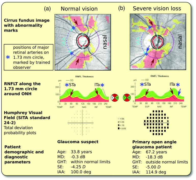
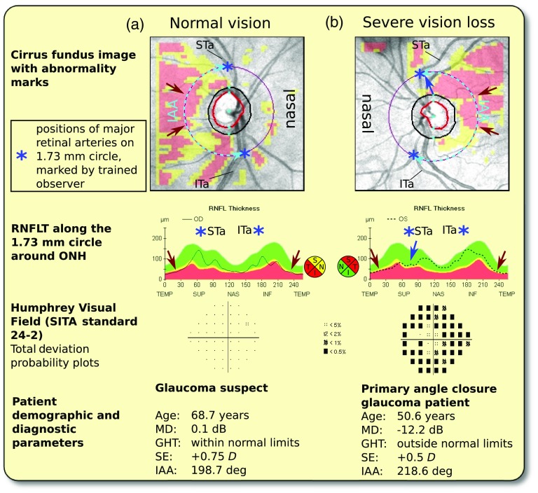
These findings emphasize the importance of considering individual anatomical variations of the RNFL bundle geometry in the interpretation of ophthalmic clinical OCT scans. However, as glaucoma is accompanied by RNFL thinning due to loss of retinal ganglion cell axons, RNFLT measurements of glaucoma patients do not necessarily reveal the predisease individual RNFL geometry of the respective patient. In contrast to RNFLT peaks, major blood vessels are typically easily recognizable on fundus photographs, which are routinely obtained in clinical practice. Previous OCT RNFLT studies have shown strong correlations of the local thickness maxima of the major RNFL bundles with the main temporal veins and arteries7,8 and vascularization density,9 and taking individual artery locations on a single circle around the optic nerve head (ONH) into account considerably improved diagnostic performance of RNFL defects.4 In a prior work,10 we systematically studied a large set of retinal artery- and vein-related parameters and found the closest relationship between SE and the angle between the two major retinal temporal arteries (interartery angle, IAA) at a radius of 1.73 mm around the ONH. At the same time, the IAA was unrelated to glaucoma severity measured by VF mean deviation. This makes the IAA at an eccentricity of 1.73 mm the ideal candidate for the development of a personalized evaluation of retinal OCT scans based on individual eye anatomy for the purpose of glaucoma diagnosis. To demonstrate the substantial diagnostic challenges of abnormal IAAs, Figs. 1 and 2 show illustrative examples of eyes with abnormally small (Fig. 1) and large (Fig. 2) IAA, respectively, and their corresponding RNFLT abnormality patterns in the absence and presence of glaucomatous vision loss.
Fig. 1.
Illustrative RNFLT abnormality patterns of eyes with extreme angles between major STa/ITa (IAA), part 1: patients with small IAA. (a) Glaucoma suspect without VF loss. As illustrated on the plot of RNFLT around the 1.73-mm radius circle (central panel), the patient’s individual RNFLT maxima are in close proximity to the STa/ITa locations (blue asterisks), which is in agreement with previous studies that showed strong correlations between RNFLT maxima and major retinal blood vessels in absence of glaucomatous RNFL thinning. The patient’s individual RNFLT humps, however, are displaced in temporal direction compared to the humps of the Cirrus RNFLT norms (red/yellow/green colored regions), and at the positions of the latter, the naturally thin RNFL of the patient is marked as abnormal (red arrows). (b) Patient with severe vision loss. Large parts of the areas marked as abnormal are at similar locations as for patient A, as denoted by the red arrows. In contrast to patient A, at the patient’s individual ITa/STa locations, RNFLT is severely decreased. However, at the patient’s ITa location, the machine’s normative data expect naturally thin RNFL, so the corresponding region around the blue arrow is not marked as abnormal. MD, VF mean deviation in decibel; GHT, glaucoma hemifield test; SE, spherical equivalent of refractive error in diopters ().
Fig. 2.
Illustrative (RNFLT) abnormality patterns, part 2: patients with large IAA. The results are analogous to Fig. 1, but the patients’ individual RNFLT humps are displaced in nasal direction, so the abnormality is focused on the temporal area (red arrows). As in Fig. 1, for the patient with severe vision loss (b), the region surrounding one of the patient’s individual blood vessel locations (STa) is not marked as abnormal although it is likely that substantial RNFL thinning has occurred (blue arrow). MD, VF mean deviation in decibel; GHT, glaucoma hemifield test; SE, spherical equivalent of refractive error in diopters (D).
The aim of this work is to systematically investigate the effects of SE and IAA on OCT abnormality patterns independent of glaucoma severity. In particular, we (1) quantify and compare possible diagnostic bias due to SE and IAA as percentage of the affected retinal area, (2) study precisely which retinal locations around the ONH are subject to systematic biases introduced by SE and IAA variations, and (3) investigate whether the previously reported impact of SE, particularly of myopia, can solely be explained by the effect of the SE-specific IAA variation. A companion paper in the same issue11 investigates the according impact of ONH-related parameters that are associated with SE.
2. Methods
This retrospective study was approved by the institutional review board of Massachusetts Eye and Ear (MEE), which waived the need for informed consent. The study adheres to the Declaration of Helsinki.
2.1. Subjects and Data
In the initial selection process, VFs and OCT ONH scans of all patients measured at the clinical glaucoma practice of MEE between 2011 and 2014 were electronically transferred from the machines (Humphrey Field Analyzer HFA-II and Cirrus HD-OCT, Software version 6.5, Carl Zeiss Meditec AG, Jena, Germany) if the following criteria were met: the patient had at least one Humphrey SITA Standard 24–2 VF with false-positive/negative rates and fixation loss rate and a Cirrus OCT scan, protocol optic disc cube , software version 6.5, with a signal strength , within 1 year from the VF measurement. If more than one OCT/VF pair per eye met the criteria, the most recent measurement was selected. If both eyes of a patient matched the criteria, one eye was randomly chosen. Thereby, in total, OCT/VF measurement pairs of 2161 eyes of 2161 patients were electronically transferred from the machines.
2.2. Data Preprocessing and Reliability Checks
The Cirrus ONH OCT scan comprises an area of , approximately centered around the optic disc. The ONH center was determined by the Cirrus software as the centroid of Bruch’s membrane opening12 and marked on the fundus image. After the export from the machine, the thickness color maps and the corresponding fundus images of each eye were centered according to the ONH center. Scans with ONH centers that deviated more than 0.3 mm in vertical or horizontal direction from the fundus image center were excluded, and for the further data analyses, 0.3 mm of all edges of the centered images were cut to ensure the availability of data over the complete area for each centered image.
All fundus images were visually inspected by a trained observer for motion artifacts due to eye movements during the scan. If a vessel shift of at least one vessel diameter or a visible shift within the optic disc area was detected, the respective scan was excluded. Black areas on the color thickness plot denote missing data. Scans with black pixels on relevant areas of the color thickness plot were excluded as well. SE of refractive error (determined by subjective refraction) was extracted from the patient’s MEE medical records. Some of the patients were referred to MEE glaucoma service by external clinical institutions or practitioners, so their refractive error was not tested at MEE and not available in the patient records. These patients were excluded from SE-related data analyses. As nuclear cataract and cataract surgery may alter SE, we checked the medical records of the patients for cataract diagnoses and excluded all patients with visually significant cataract (3+ nuclear sclerosis or worse), pseudophakia, or aphakia from SE-related data analyses.
2.3. Vessel Tracking
For vessel tracking, graphical parameters on the fundus images, such as the standard scanning circle or abnormality ratings, were switched off, and a circle with radius of 1.73 mm around the ONH center was overlaid on the image. A trained observer marked the intersections of the circle with the major superior/inferior temporal arteries (STa/ITa) on each centered fundus image that matched the aforementioned criteria. Illustrative examples of STa/ITa intersections with the 1.73 mm circle are provided in Figs. 1 and 2. To facilitate the vessel tracking by the trained observer, we developed a custom software in the programming language R (version 3.1.1, R Foundation, Vienna, Austria).
For data analysis of tracked vessels, all eyes were represented in right-eye orientation. We used the coordinate system definitions from the Cirrus device, which defines the angular position of zero on the horizontal line temporal to ONH and counts angles clockwise.
2.4. Statistics
Statistical analyses were performed by the software R (version 3.1.1, R Foundation). To study how artery locations and SE impact RNFLT abnormality independent of glaucoma severity and whether SE-related abnormality effects can be fully explained by artery location effects, we computed multivariate logistic regression models with the occurrence of abnormality at each single of the 40,401 pixels of the Cirrus abnormality images as regressands (i.e., dependent variables) and VF mean deviation (MD; an established glaucoma severity measure), IAA, respectively SE, and their combination as regressors (i.e., independent variables). The specific impacts of the respective regressors were assessed by model comparisons by likelihood ratio tests. Table 1 details and describes the models applied to each pixel. Illustrative examples are provided in Sec. 3.2. The values of the 40,401 tests for each parameter were adjusted for multiple comparisons by the false discovery rate method.13
Table 1.
Description of regressors (independent variables) of the different models applied to each of the 40,401 pixels of the images of the circumpapillary region. Regressand (dependent variable) was the Cirrus abnormality rating at the respective pixel. The leftmost column contains the respective model identifiers used throughout this study, the central column the corresponding regressors. The occurrence of RNFLT abnormality marks was fitted to VF mean deviation (MD), angle between superior and inferior artery (IAA), and spherical equivalent of refractive error (SE). Model comparisons by likelihood ratio tests assess the respective significance of the parameter ( after adjustment for multiple comparisons). MD acts as a “null model,” so the significance of a parameter at a specific pixel means that the parameter has an impact at the corresponding retinal location which is not explained by glaucoma severity. Illustrative examples for further understanding are presented in Sec. 3.2.
| Model | Parameters | Explanation |
|---|---|---|
| MD | “Null model” (glaucoma severity) | |
| MD + IAA | Additional IAA effect | |
| : IAA | MD | versus | Effect of IAA unexplained by glaucoma severity |
| MD + SE | Additional ametropia effect | |
| : SE | MD | versus | Effect of SE unexplained by glaucoma severity |
| MD + IAA + SE | Additional effect of both parameters | |
| : SE | IAA,MD | versus | Effect of SE unexplained by IAA and glaucoma severity |
3. Results
1480 of the 2161 eyes were excluded due to OCT quality-related parameters (see Sec. 2), as detailed in Table 2. Table 3 contains demographical and diagnostic details for the whole population of the remaining 691 eyes as well as separated by quartiles of IAA at the Cirrus standard radius (1.73 mm). 246 eyes were excluded from all SE-related data analyses due to cataract or due to unavailability of SE (see Table 2). Table 4 contains demographical and diagnostic details for the remaining 445 eyes, additionally separated by quartiles of SE.
Table 2.
Results of the iteratively applied exclusion criteria (see Sec. 2). Note that the number of excluded eyes is always relative to the number of remaining eyes in the respective previous table row. 691 eyes were selected after measurement artifact exclusion and 445 eyes after criteria related to SE of refractive error.
| Criterion | #Eyes excluded | #Eyes remaining |
|---|---|---|
| Initially transferred from machines | 2161 | |
| Out of center | 221 | 1940 |
| Motion artifacts | 1082 | 858 |
| Missing data | 167 | 691 |
| Missing SE data | 122 | 569 |
| Cataract | 124 | 445 |
Table 3.
Demographics by quartiles (specified as percentages and ranges in the column headers) of IAA at the Cirrus standard radius (1.73 mm). OAG, primary or secondary open angle glaucoma; ACG, primary or secondary angle closure glaucoma; MMG, mixed mechanism glaucoma; MD, mean deviation in decibel; PSD, pattern standard deviation; GHT, glaucoma hemifield test (GHT result categories: WNL/ONL, within/outside normal limits; BL, borderline; GRS, general reduction of sensitivity).
| Quartiles of IAA |
Total | ||||
|---|---|---|---|---|---|
| 0% to 25% [84.7 deg, 134.3 deg] | 25% to 50% [134.3 deg, 148.6 deg] | 50% to 75% [148.6 deg, 162.1 deg] | 75% to 100% [162.1 deg, 218.6 deg] | ||
| 173 | 173 | 172 | 173 | 691 | |
| Sex (m/f) | 76/97 | 79/94 | 66/106 | 88/85 | 309/382 |
| Age (years) | |||||
| Age range (years) | [16.7, 91.1] | [16.4, 98.8] | [17.7, 90.7] | [17.2, 91.3] | [16.4, 98.8] |
| Race/Ethnicity | |||||
| European descent | 125 | 140 | 125 | 121 | 511 |
| Asian descent | 21 | 8 | 8 | 9 | 46 |
| African descent | 9 | 16 | 21 | 25 | 71 |
| Hispanic identity | 6 | 4 | 13 | 11 | 34 |
| Mixed/other | 11 | 5 | 5 | 7 | 28 |
| Diagnosis | |||||
| OAG | 77 | 91 | 78 | 70 | 316 |
| ACG | 2 | 2 | 3 | 8 | 15 |
| MMG | 7 | 3 | 3 | 4 | 17 |
| Suspect | 72 | 64 | 75 | 80 | 291 |
| Normal | 15 | 13 | 13 | 11 | 52 |
| Glaucoma parameters | |||||
| MD (dB) | |||||
| PSD | |||||
| Glaucoma Hemif. Test | |||||
| GHT WNL | 76 | 78 | 91 | 83 | 328 |
| GHT BL | 23 | 12 | 14 | 20 | 69 |
| GHT ONL | 62 | 72 | 57 | 60 | 251 |
| GHT GRS | 9 | 8 | 9 | 9 | 35 |
| GHT BL/GRS | 3 | 3 | 1 | 1 | 8 |
Table 4.
As Table 3, but for SE of refractive error in Diopters (D) for the respective subset of eyes.
| Quartiles of SE of refractive error |
Total | ||||
|---|---|---|---|---|---|
| 0% to 25% | 25% to 50% | 50% to 75% | 75% to 100% [0.8D, 6.4D] | ||
| 116 | 110 | 108 | 111 | 445 | |
| Sex (m/f) | 64/52 | 56/54 | 52/56 | 30/81 | 202/243 |
| Age (years) | |||||
| Age range (years) | [16.7,79.1] | [16.4,81.8] | [30.4,91.3] | [40.7,88.8] | [16.4,91.3] |
| Race/ethnicity | |||||
| European descent | 88 | 77 | 75 | 86 | 326 |
| Asian descent | 14 | 13 | 3 | 3 | 33 |
| African descent | 6 | 11 | 16 | 13 | 46 |
| Hispanic identity | 2 | 5 | 11 | 4 | 22 |
| Mixed/other | 5 | 4 | 3 | 5 | 17 |
| Diagnosis | |||||
| OAG | 57 | 48 | 50 | 45 | 200 |
| ACG | 0 | 0 | 3 | 2 | 5 |
| MMG | 2 | 4 | 2 | 1 | 9 |
| Suspect | 47 | 50 | 46 | 58 | 201 |
| Normal | 10 | 8 | 7 | 5 | 30 |
| Glaucoma parameters | |||||
| MD (dB) | |||||
| PSD | |||||
| Glaucoma Hemif. Test | |||||
| GHT WNL | 60 | 59 | 55 | 54 | 228 |
| GHT BL | 14 | 9 | 8 | 17 | 48 |
| GHT ONL | 37 | 34 | 41 | 35 | 147 |
| GHT GRS | 4 | 8 | 3 | 3 | 18 |
| GHT BL/GRS | 1 | 0 | 1 | 2 | 4 |
3.1. Major Artery Locations and RNFL Bundles
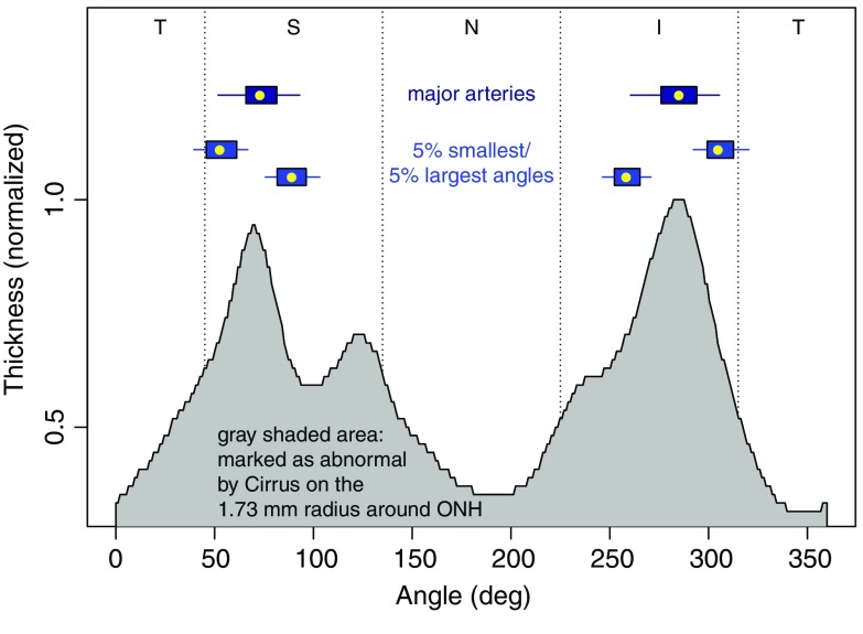
Figure 3 graphically illustrates the relationship between the RNFLT norms extracted from the Cirrus machine and the artery locations on a radius of 1.73 mm around ONH. Although the modalities (RNFLT peaks versus blood vessel locations) as well as the populations (glaucoma patients in our study versus healthy controls for the norms) are entirely different, median artery locations are closely related to the normative RNFL thickness peaks (differences: superior peaks/arteries: 3.5 deg, inferior peaks/arteries: 0.7 deg).
Fig. 3.
Artery location distributions and Cirrus RNFL thickness norms on a radius of 1.73 mm around ONH. The gray shaded area contains the 5% quantile of the Cirrus normative RNFLT around the 1.73 mm circle, based on RNFLT measurements of 284 healthy subjects.12 The thickness norms are normalized by setting the maximum to 1, as the axis is scaled with age. The age effect is restricted to linear scaling, which means, the locations of the peaks remain stable over age. Boxplots: distributions of artery locations (box: first to third quartile, central mark: median, whiskers: 5th to 95th percentile). For comparison, the artery locations of the 5% largest and smallest angles (blue boxes) are added below. Annotations: T, temporal; S, superior; N, nasal; I, inferior w.r.t. ONH.
3.2. Impact on Abnormality Profiles
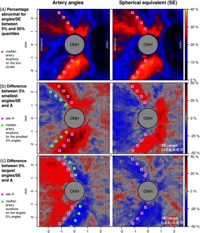
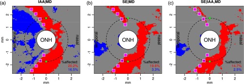
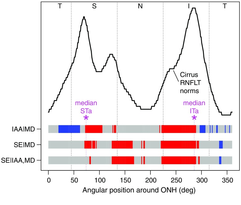
Figures 4–6 summarize the impact of IAA and SE on the spatial distribution of the Cirrus abnormality marks. Figure 4 shows the differences in the frequency of abnormality marks of the 5% smallest/largest IAA/SE values (rows B and C) with the inner 90% of the respective distributions (row A). The quantiles of the IAA distributions refer to the circle with radius 1.73 mm. To statistically quantify the IAA/SE effects independent of MD, we additionally calculated model comparisons for each of the 40,401 pixels of the images shown in Fig. 4, which analyze the variance, which is not explained by MD alone. The respective models are illustratively detailed for two selected pixels (the 90 deg and 270 deg locations on the 1.73 mm circle) in Table 5. Figure 5 shows the significant locations among the total 40,401 pixels and Fig. 6 shows the respective locations on the 1.73 mm circle. Higher abnormality ratings for smaller IAA/higher myopia (red colors) concentrate nasal to the median STa/ITa locations and for SE additionally immediately nasal to ONH. Figure 5(c) shows the effect of SE, which is unexplained by the variance caused by IAA. A comparison with B reveals that while the superotemporal abnormalities due to SE are mainly caused by the covariation of SE and IAA, substantial parts of the inferior and nasal abnormalities are independent of IAA.
Fig. 4.
Frequency of RNFLT abnormality ratings of the inner 90% of the distribution (a) and their changes (differences) for the 5% smallest (b)/largest (c) tail of the distribution for artery angles (left column) and spherical equivalent (SE, right column). The magenta squares which are added as a spatial reference to each plot denote the median artery locations on the four radii () around the ONH. Filled green circles on the artery plots denote the medians of the 5% smallest/largest angles. In the two difference plots (b and c), red color denotes an increase, blue color a decrease of abnormality marks relative to a.
Fig. 5.
Impacts of (a) IAA in addition to VF mean deviation (MD), (b) SE in addition to MD, and (c) SE in addition to IAA and MD on the frequency of abnormality marks. As positional references, the Cirrus standard circle (dashed circle), median superior/inferior temporal artery locations on the four circles (magenta squares), and the two positions shown in Table 5 (green dots) have been added. Red/blue pixels: significant ( after correction for multiple comparisons) increase/decrease of frequency of abnormality marks for decreasing IAA and SE (i.e., higher myopia). Gray areas: not significant. Red/blue numbers in bottom right corner: respective percentage of area in red/blue. The values were obtained from model comparisons by tests with the respective “null model” that contained only MD as regressor, as illustrated and detailed in Table 5 for the two specific positions marked by green dots. In summary, for myopes resp. for patients with small IAA, red pixels denote locations with increased risk of false alarms and blue pixels locations with increased risk of misses. For hyperopes/patients with large IAA, the opposite relationship holds.
Fig. 6.
Separate representation of those values illustrated in Fig. 5 which are located on the Cirrus standard circle (radius: 1.73 mm around ONH). As positional references, the Cirrus RNFLT norms (black curve) and median superior/inferior temporal arteries (STa/ITa, magenta asterisks) have been added. The bars colored in red, blue, and gray reproduce the colors from the respective locations in Fig. 5. More specifically, the top bar represents Fig. 5(a), the central bar Fig. 5(b), and the bottom bar Fig. 5(c).
Table 5.
Illustrative results of the comparisons of logistic regression models for two selected locations on the Cirrus standard circle (90 deg and 270 deg). The occurrence of RNFLT abnormality marks was fitted to VF mean deviation (MD), angle between superior and inferior artery (IAA), and SE of refractive error. In addition to the fitted coefficients (coef) and their respective values, results of model comparisons by likelihood ratio tests are shown. A significant test () denotes that the model with the additional parameter is preferred. For instance, in the last row, at position 270 deg, there is an effect of SE which is not explained by the variance of IAA and MD, that is, SE contributes to abnormality marks independently of MD and IAA. At the 90 deg position, however, this effect is not significant (). The “null model” , against which all other models are compared, fits MD, that is, all effects are analyzed in addition to the variance explained by MD. Figure 5 illustrates the values (after correction for multiple comparisons) of the tests for all positions measured by Cirrus. The two locations used in this table are marked by green dots. Figure 6 illustrates the subset of 256 locations which are located on the Cirrus standard circle.
| Model | Parameters | Position: 90 deg | Position: 270 deg | |||
|---|---|---|---|---|---|---|
| Coef. | Coef. | |||||
| MD | Intercept | 0.000 | 0.000 | |||
| MD | 0.000 | 0.000 | ||||
| MD + IAA | Intercept | 2.66 | 0.009 | 3.34 | 0.000 | |
| MD | 0.000 | 0.000 | ||||
| IAA | 0.000 | 0.000 | ||||
| : IAA | MD | versus | 0.000 | 0.000 | |||
| MD + SE | Intercept | 0.000 | 0.000 | |||
| MD | 0.000 | 0.000 | ||||
| SE | 0.009 | 0.000 | ||||
| : SE | MD | versus | 0.010 | 0.000 | |||
| MD + IAA + SE | Intercept | 2.19 | 0.039 | 2.52 | 0.004 | |
| MD | 0.000 | 0.000 | ||||
| IAA | 0.000 | 0.000 | ||||
| SE | 0.104 | 0.000 | ||||
| : SE | IAA,MD | versus | 0.109 | 0.000 | |||
4. Discussion
4.1. Impact of Interartery Angles on OCT RNFLT Abnormality Patterns
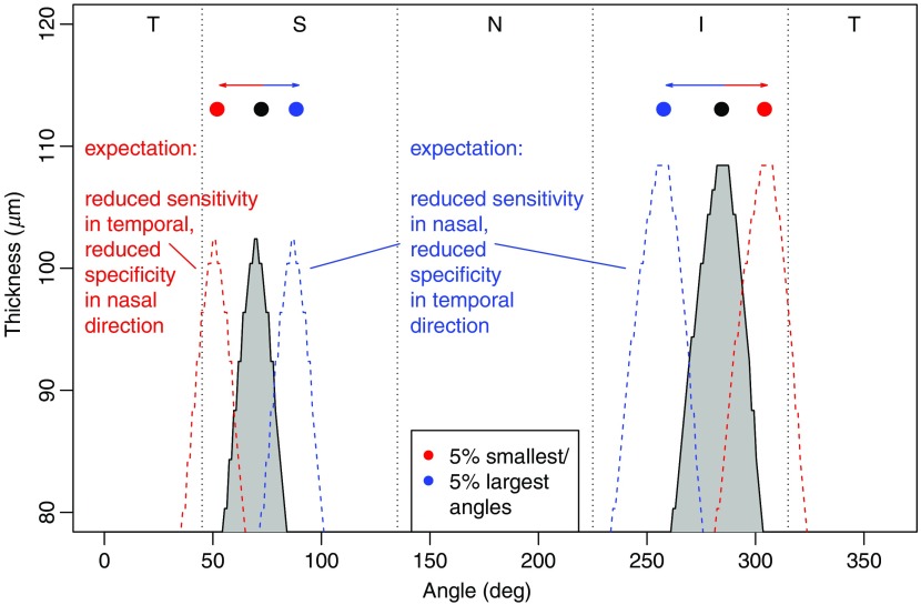
OCT manufacturers generate color plots of deviations of individual RNFL thicknesses from norms, which are used as an adjunct for clinical glaucoma diagnosis. The thickness norms vary substantially over location (gray-shaded area in Fig. 3). Individual deviations of retinal nerve fiber bundle anatomy may therefore impair deviation color plots, as shown in Fig. 7. Under the assumption that, for instance, the 5% patients with the smallest artery angles have their natural RNFL thickness profile shifted according to their individual artery locations (as sketched by the stroked red line), locations temporal to the median artery location of the total population are naturally thicker. Therefore, possible true RNFL defects are more likely to be missed (which means a reduction in sensitivity), as illustrated in the example in Fig. 1(b) by the blue arrow. At the median artery location of the total population, on the other hand, these patients have a naturally thin RNFL. These areas are therefore more likely to be marked as abnormal by the OCT machine even for healthy individuals (which means a reduction in specificity), as shown by the red arrows in Fig. 1. Analogously, specificity and sensitivity shifts can be postulated for the patients with the largest artery angles (blue in Fig. 7). Our results for IAA (Figs. 4–6) confirm these postulations. Independent of MD, 20.2% specificity and 16.5% significant sensitivity shifts for patients with smaller IAA over the total scanning area could be identified [Fig. 5(a)], and their respective spatial locations conform with our predictions, both on the Cirrus standard circle (Fig. 6) and the total area [Fig. 5(a)].
Fig. 7.
Expectations of sensitivity and specificity changes of the Cirrus RNFLT abnormality profiles by artery location, adapted from Fig. 3. Under the assumption that the RNFLTs of a patient follow the norms (gray shaded peaks taken from the gray shaded area in Fig. 3) apart from being spatially shifted according to the patient’s individual artery location, for patients within the 5% smallest artery angles (dashed red curve), reduced sensitivity in temporal and reduced specificity in nasal regions relative to the median artery locations (filled black circles) can be expected. The according expectations for patients within the 5% largest artery angles (blue) are reduced sensitivity in nasal and reduced specificity in temporal directions.
These results support the proposal by Rho et al.4 to introduce artery location-specific norms and are compatible with approaches to compensate for RNFL variability by SE, vessel density, and further retinal parameters14 as well as with the recent finding that, whereas more precise VF and OCT measurements did not improve structure function correlations, individualized ONH sector maps yielded substantial improvements.15
4.2. Impact of Spherical Equivalent of Refractive Error on OCT RNFLT Abnormality Patterns
While the area of specificity shifts due to SE is similarly large as for IAA (19.6% versus 20.2%, see Fig. 5), the effect on sensitivity is substantially smaller (3.3% versus 16.5% for IAA). Furthermore, our findings clearly show that the SE-induced effects cannot solely be attributed to the covariation of SE and IAA. Figures 5(c) and 6 (bottommost row) demonstrate that particularly the inferior and nasal areas of SE-related specificity shifts are independent of IAA. Therefore, previously suggested artery-specific norms4 are not sufficient to address ametropia-related RNFLT abnormality patterns.
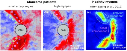
As a demonstration of the external validity of our study, note the remarkable similarity of our Figs. 4(b) (right column) and Fig. 3 in the work of Leung et al.5 in which the authors show a frequency distribution of abnormality ratings of 189 healthy myopes, as shown in Fig. 8. As there were no glaucoma patients or suspects in their study, any areas with frequency of abnormality ratings above 5% can be attributed to reduced specificity locations due to myopia. The similarity supports our conclusion that the red areas in Figs. 4(b) (right column) and 5(b) are indeed attributable to regions of specificity loss and that the red nasal region in Fig. 5(c) is a relevant IAA-independent component and an indication that difficulties in interpreting abnormality plots of myopes not only arise from lower angles of RNF bundles.
Fig. 8.
Two independent components of specificity loss (i.e., increased risk of false alarms) for myopes. In (a) and (b), angular (cyan) and nasal (magenta) components are graphically superimposed on Fig. 4(b). The same locations were preferably rated as abnormal by the Cirrus machine in a population of 189 healthy myopes in a previous study, as illustrated in (c). The plot of the frequency of abnormality ratings over space in C was reproduced with permission from Fig. 3 in the work of Leung et al.5 In (c), warmer, “more red” colors denote a higher frequency of abnormality marks.
Increasing ocular axial length typically does not uniformly magnify the eye but transforms a naturally oblate (flat curvature) retina into a prolate (increased curvature) shape.16 It has been discussed that for longer axial length therefore the retina gets “dragged” toward the temporal raphe, so temporal fibers get compressed and nasal fibers stretched,17–19 which might contribute to the increased number of abnormality ratings in nasal direction for myopes but not for small artery angles. In addition, the increased incidence of tilted discs in myopes might have an impact on the spatial RNFL thickness distribution.18–21 Chung and Yoo18 argued that the placement of the standard scanning circle by Cirrus can be wrong for tilted discs. Their manual repositioning of the scanning circles for tilted discs yielded a statistically significant reduction of abnormality ratings in the nasal but not in the other quadrants. Note, however, that the results regarding disc tilt presented in our companion paper11 indicate that this explanation is not sufficient, as the disc tilt effect on RNFLT abnormality patterns seems to be fully explained by a covariation with SE.
Apart from the parameters discussed above, eye size-specific effects on the RNFLT abnormality patterns of myopes have been extensively discussed.3,6,22–24 Kang et al.22 argued that the OCT scanning area is not adjusted for ocular magnification in eyes with larger axial length. For instance, according to a widely applied eye size magnification formula, for a myopic eye with axial length of 26 mm, the true standard scanning circle would be 1.85 mm instead of the 1.73 mm assumed by the Cirrus machine. As RNFL thickness naturally decreases with increasing eccentricity, there would be an underestimation of average thickness in healthy eyes with larger axial length, and the authors suggest a correction factor. Following this line of reasoning, the difference plot for myopes in Fig. 4(b) (right column) and the model comparison plot in Fig. 5(b) should have uniformly more red pixels (higher abnormality ratings), as every single pixel would have been measured at a higher eccentricity than expected by Cirrus. However, while there are considerable red areas, the red values are clearly not uniformly distributed over space. Therefore, eye size correction is not sufficient to address ametropia-induced RNFLT abnormality patterns.
4.3. Clinical Implications
Figures 4–6 suggests the following clinical implications: first, abnormal IAAs impose a greater challenge on the interpretation of OCT RNFLT abnormality profiles than ametropia. Second, patients with myopia/small IAAs face a risk of false-positive interpretations that is raised up to 50% and further amplified by the shape of the patterns, as they resemble typical nerve fiber trajectories. Third, large IAA, but not hyperopia, increases the risk of false-positive interpretations in the superotemporal area. Figures 5 and 6 may be used as an adjunct for the clinical interpretation of OCT scans of eyes with abnormal IAAs or ametropia.
Currently, applied normative datasets of RNFLT of OCT manufacturers consider age as the only relevant parameter to explain interindividual variability. Our results demonstrate that IAA and ametropia have substantial and independent impacts on RNFLT variability as well and should be included in future normative data sets.
Acknowledgments
We wish to thank Drs. Peter J. Bex, Louis R. Pasquale, Lucy Q. Shen, Hiroshi Ishikawa, Joel Schuman, and Gadi Wollstein for their collaboration, discussions and insightful suggestions. This work was supported by the Massachusetts Lions Foundation (T.E., N.B., M.W.), NIH grants R01 EY018664 and NEI Core grant P30EYE003790 (T.E., N.B., M.W.), Harvard Glaucoma Center of Excellence (T.E.), China Scholarship Council (Q.J., H.W.), BrightFocus Foundation (T.E., M.W.), and Research to Prevent Blindness (T.E., N.B., M.W.).
Biographies
Tobias Elze is an assistant professor of ophthalmology at Harvard Medical School. He received his PhD in computer science from Max Planck Institute for Mathematics in the Sciences in Leipzig, Germany, in 2011. He is the author of more than 20 research papers. His current research interests include applications of optical coherence tomography to the field of ophthalmology in order to improve the diagnosis of eye diseases and to monitor their progression over time.
Biographies for the other authors are not available.
Disclosures
None of the authors has any conflict of interest to disclose.
References
- 1.Huang D., et al. , “Optical coherence tomography,” Science 254(5035), 1178–1181 (1991). 10.1126/science.1957169 [DOI] [PMC free article] [PubMed] [Google Scholar]
- 2.Quigley H. A., “Glaucoma,” Lancet 377(9774), 1367–1377 (2011). 10.1016/S0140-6736(10)61423-7 [DOI] [PubMed] [Google Scholar]
- 3.Yoo Y. C., Lee C. M., Park J. H., “Changes in peripapillary retinal nerve fiber layer distribution by axial length,” Optom. Vision Sci. 89(1), 4–11 (2012). 10.1097/OPX.0b013e3182358008 [DOI] [PubMed] [Google Scholar]
- 4.Rho S., et al. , “Improvement of diagnostic performance regarding retinal nerve fiber layer defect using shifting of the normative database according to vessel position,” Invest. Ophthalmol. Visual Sci. 55(8), 5116–5124 (2014). 10.1167/iovs.14-14630 [DOI] [PubMed] [Google Scholar]
- 5.Leung C. K.-S., et al. , “Retinal nerve fiber layer imaging with spectral-domain optical coherence tomography: interpreting the RNFL maps in healthy myopic eyes,” Invest. Ophthalmol. Visual Sci. 53(11), 7194–7200 (2012). 10.1167/iovs.12-9726 [DOI] [PubMed] [Google Scholar]
- 6.Yamashita T., et al. , “Relationship between supernormal sectors of retinal nerve fibre layer and axial length in normal eyes,” Acta Ophthalmol. 92(6), E481–E487 (2014). 10.1111/aos.2014.92.issue-6 [DOI] [PubMed] [Google Scholar]
- 7.Hood D. C., et al. , “Blood vessel contributions to retinal nerve fiber layer thickness profiles measured with optical coherence tomography,” J. Glaucoma 17(7), 519–528 (2008). 10.1097/IJG.0b013e3181629a02 [DOI] [PMC free article] [PubMed] [Google Scholar]
- 8.Hood D. C., et al. , “The location of the inferior and superior temporal blood vessels and interindividual variability of the retinal nerve fiber layer thickness,” J. Glaucoma 19(3), 158–166 (2010). 10.1097/IJG.0b013e3181af31ec [DOI] [PMC free article] [PubMed] [Google Scholar]
- 9.Pereira I., et al. , “Correlation between retinal vessel density profile and circumpapillary RNFL thickness measured with Fourier-domain optical coherence tomography,” Br. J. Ophthalmol. 98(4), 538–543 (2014). 10.1136/bjophthalmol-2013-303910 [DOI] [PubMed] [Google Scholar]
- 10.Wang M., et al. , “The interrelationship between refractive error, blood vessel anatomy, and glaucomatous visual field loss,” Transl. Vision Sci. Technol. (in press). [DOI] [PMC free article] [PubMed] [Google Scholar]
- 11.Baniasadi N., et al. , “Ametropia, retinal anatomy, and OCT abnormality patterns in glaucoma. 2. Impacts of optic nerve head parameters,” J. Biomed. Opt. (in press). [DOI] [PMC free article] [PubMed]
- 12.Carl Zeiss Meditec Inc., Cirrus HD-OCT User Manual, Carl Zeiss Meditec Inc., Dublin, California: (2012). [Google Scholar]
- 13.Benjamini Y., Hochberg Y., “Controlling the false discovery rate: a practical and powerful approach to multiple testing,” J. R. Stat. Soc. Ser. B–Methodol. 57(1), 289–300 (1995). [Google Scholar]
- 14.Pereira I., et al. , “Multivariate model of the intersubject variability of the retinal nerve fiber layer thickness in healthy subjects,” Invest. Ophthalmol. Visual Sci. 56(9), 5290–5298 (2015). 10.1167/iovs.15-17346 [DOI] [PubMed] [Google Scholar]
- 15.Ganeshrao S. B., et al. , “Enhancing structure-function correlations in glaucoma with customized spatial mapping,” Ophthalmology 122(8), 1695–1705 (2015). 10.1016/j.ophtha.2015.04.021 [DOI] [PubMed] [Google Scholar]
- 16.Atchison D. A., et al. , “Shape of the retinal surface in emmetropia and myopia,” Invest. Ophthalmol. Visual Sci. 46(8), 2698–2707 (2005). 10.1167/iovs.04-1506 [DOI] [PubMed] [Google Scholar]
- 17.Kim M. J., Lee E. J., Kim T.-W., “Peripapillary retinal nerve fibre layer thickness profile in subjects with myopia measured using the Stratus optical coherence tomography,” Br. J. Ophthalmol. 94(1), 115–120 (2010). 10.1136/bjo.2009.162206 [DOI] [PubMed] [Google Scholar]
- 18.Chung J. K., Yoo Y. C., “Correct calculation circle location of optical coherence tomography in measuring retinal nerve fiber layer thickness in eyes with myopic tilted discs,” Invest. Ophthalmol. Visual Sci. 52(11), 7894–7900 (2011). 10.1167/iovs.11-7712 [DOI] [PubMed] [Google Scholar]
- 19.Hwang Y. H., Yoo C., Kim Y. Y., “Myopic optic disc tilt and the characteristics of peripapillary retinal nerve fiber layer thickness measured by spectral-domain optical coherence tomography,” J. Glaucoma 21(4), 260–265 (2012). 10.1097/IJG.0b013e31820719e1 [DOI] [PubMed] [Google Scholar]
- 20.Shin H., Park H. L., Park C. K., “The effect of myopic optic disc tilt on measurement of spectral-domain optical coherence tomography parameters,” Br. J. Ophthalmol 99(1), 69–74 (2015). 10.1136/bjophthalmol-2014-305259 [DOI] [PubMed] [Google Scholar]
- 21.Baniasadi N., et al. , “Associations between optic nerve head related anatomical parameters and refractive error over the full range of glaucoma severity,” Transl. Vision Sci. Technol. 6(4), 9 (2017). 10.1167/tvst.6.4.9 [DOI] [PMC free article] [PubMed] [Google Scholar]
- 22.Kang S. H., et al. , “Effect of myopia on the thickness of the retinal nerve fiber layer measured by cirrus HD optical coherence tomography,” Invest. Ophthalmol. Visual Sci. 51(8), 4075–4083 (2010). 10.1167/iovs.09-4737 [DOI] [PubMed] [Google Scholar]
- 23.Hirasawa K., et al. , “Determination of axial length requiring adjustment of measured circumpapillary retinal nerve fiber layer thickness for ocular magnification,” PLoS ONE 9(9), e107553 (2014). 10.1371/journal.pone.0107553 [DOI] [PMC free article] [PubMed] [Google Scholar]
- 24.Nowroozizadeh S., et al. , “Influence of correction of ocular magnification on spectral-domain OCT retinal nerve fiber layer measurement variability and performance,” Invest. Ophthalmol. Visual Sci. 55(6), 3439–3446 (2014). 10.1167/iovs.14-13880 [DOI] [PubMed] [Google Scholar]


