Abstract
Target motion–induced uncertainty in particle therapy is more complicated than that in X-ray therapy, requiring more accurate motion management. Therefore, a hybrid motion-tracking system that can track internal tumor motion and as well as an external surrogate of tumor motion was developed. Recently, many correlation tests between internal and external markers in X-ray therapy have been developed; however, the accuracy of such internal/external marker tracking systems, especially in particle therapy, has not yet been sufficiently tested. In this article, the process of installing an in-house hybrid internal/external motion-tracking system is described and the accuracy level of tracking system was acquired. Our results demonstrated that the developed in-house external/internal combined tracking system has submillimeter accuracy, and can be clinically used as a particle therapy system as well as a simulation system for moving tumor treatment.
Keywords: respiratory gating, internal/external fiducials, marker tracking, correlation, patient external surface
INTRODUCTION
In the radiation treatment paradigm, the respiratory motion of the organs in the abdomen and the thoracic cavity [1–6] hinders the precise delivery of radiation to targets in the abdomen or chest. To compensate for respiration-induced tumor motion, large margins around the tumor are required to ensure adequate target dose coverage, which in turn results in delivery of high-dose radiation to normal tissues adjacent to the tumor. As a solution to this problem, motion management techniques, such as respiratory gating or dynamic multileaf collimator (DMLC) beam tracking, have been proposed to reduce the incidence and severity of normal tissue complications and to increase local control through dose escalation in X-ray therapies [7–10]. In particular, the gating technique based on external surrogates to monitor respiration and predict target position has been a standard treatment for tumors in the clinic (i.e. 3D conformal radiotherapy, also available for intensity-modulated radiotherapy [11–15]).
Monitoring of an external surrogate has an important advantage in particle therapy, since the distance between the beam entrance surface to the target position should not be changed to deliver the range of the Bragg peak at the planned position. However, when the external surrogates are not well correlated with internal target motion, then monitoring of respiration using only external surrogates involves uncertainties in predicting the precise target phase and/or position. There has been much research into the uncertainties of external marker tracking and its correlation with tumor motion [16–19]. Beddar et al. reported that targeting based on the correct respiratory amplitude alone would not guarantee that the entire tumor volume is within the target field [16]. Yan et al. also reported that a single external marker cannot provide sufficient and reliable tracking information for tumor motion [13]. To overcome these drawbacks, there are commercially available X-ray therapy machines equipped with imagers that can monitor the internal target during treatment.
Recently, particle therapy has been introduced in many clinics because of the superiority of protons in sparing normal tissues due to the inherent characteristic of the sharp dose fall-off of the Bragg peak. One of the drawbacks of the prescribed sharp dose fall-off is that higher accuracy is required in the treatment compared with that in photon therapy. Photon therapy has a small change of dose for a small change of depth; therefore, it can achieve high accuracy using the internal marker tracker only. However, the dose difference in particle therapy is complicated because the margin size should be different in the proximal, distal and lateral beam directions, as well as with respect to the energy. Therefore, using external surrogates together with the internal tracking system is the best way to treat moving targets accurately in particle therapy.
In our site, external surrogates are being used for treating moving targets with the breath holding or gating technique. In determining the planning target volume (PTV), an additional treatment margin is being applied to allow for the inconsistency between the target position and the external surrogate's measured position, which actually reduces the benefit of particle therapy by increasing the normal tissue toxicity surrounding the target. The obvious solution for this problem would be internal marker tracking that accurately indicates the target position and minimizes the treatment margin. For example, ‘Hitachi’ has been working on the development of a real-time tumor-tracking proton therapy system with Hokkaido University, and this is now available for clinical use [20]. However, in some cases the external surrogate can be accurate enough for use. In addition, the extra imaging dose can be large if only internal markers are used for treatment. Therefore, intermittent internal marker position verification with X-ray imagers, together with external marker tracking, was designed—i.e. a hybrid system. The advantage of this hybrid system is that the relative weight attributed between the external surrogate information and the internal marker information can be decided according to the each patient's characteristics. For this purpose, an internal–external motion monitoring system was developed in this study. A system was designed that combines a high-frame-rate stereotactic radiography imaging system (G-arm system) for internal marker tracking and the ‘Vicon’ (Vicon Motion Systems Ltd, UK) camera for real-time accurate external motion tracking. To display the results of the motion analysis of various images obtained by the G-arm system and Vicon cameras, the software named ‘Coregistration Algorithm’ was developed. This software simultaneously displays the 3D coordinates of each internal/external marker position on one monitor. Also, the accuracy of the developed internal/external marker tracking system was verified.
MATERIALS AND METHODS
BrainLAB phantom
For testing the accuracy of each independent external and internal marker tracking system, a BrainLAB ET Gating Phantom Ver. 1.0.0 (BrainLAB AG, Feldkirchen, Germany) was used (Fig. 1). This phantom consists of two moving platforms, one that moves in the superior–inferior (SI) direction and another that moves in the anterior–posterior (AP) direction. The two platforms are connected by a wire and driven by a single-step motor. In the experiments, an approximately sine wave motion with a 20.0 mm, 15 mm and 10 mm peak-to-peak amplitude and a period of 4.0 s was used in each direction. A fiducial (internal marker) was inserted in a 2 × 2 × 2 cm3 cubic bolus and placed on the platform for internal marker tracking. Three reflective markers were placed on the platform to test the external marker tracking system.
Fig. 1.
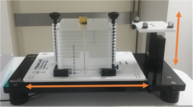
The BrainLAB ET gating phantom set-up. The two platforms move in SI and AP directions, respectively.
The G-arm system
The motion of an internal marker was visualized using fluoroscopic X-ray images. The conventional C-arm X-ray imager is a medical imaging device based on X-ray technology and can be used flexibly for imaging various organs [21]. C-arm provides high-resolution X-ray images in real time, thus allowing the physician to monitor progress at any point during the operation and to immediately make any needed corrections. However, C-arm has some limitations because it only tracks in two dimensions: a 3D tracking system is required to accurately define the location of a tumor. Consequently, a G-arm fluoroscopy system that simultaneously shows AP and lateral (LT) views with a maximum frame rate of 28 frames/s was manufactured. The G-arm fluoroscopy has two X-ray sources and detectors positioned on a vertical G-shaped arm. The sources are X-ray tubes (E7833x, Toshiba Medical Systems, Tokyo, Japan) operating in a voltage range from 40 to 125 kV. The detectors are image intensifiers (E5830SD-P4A, Toshiba Medical Systems, Tokyo, Japan). The images produced are 22.86 cm in diameter, and the output voltage is 24V DC. In the image intensifiers, the distributed X-rays from the source are converted into a corresponding light image. The light image is converted to a digital signal with a charge coupled device (CCD) and is transmitted to a PC for tracking. Using this system, the real-time biplane images of the target object can be obtained. These images are displayed on the monitor for internal marker tracking. Gold or steel markers were used for internal markers because of their good visibility in radiography.
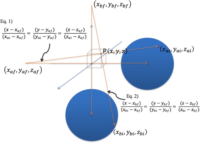
The ‘G-view’ software was developed for tracking the target motion of biplane images. Figure 2 shows the displayed images produced by the tracking software ‘G-view’. The region of interest (ROI) was selected for shape-based tracking. When the operator selects an ROI in a frame, the same shape is used in the next frame to identify the displaced target position. If the number of similar shapes, i.e. ‘pixel blocks’, is more than one per frame, the nearest pixel block from the previous frame's ROI block is selected. Using a similar shaped ROI in each frame, the mutual information algorithm was applied to increase tracking accuracy [22, 23]. Figure 3 illustrates calibration process and the determination of the 3D coordinates of markers in the biplane images. In this figure, Equations 1 and 2 share one point at (x, y, z), allowing us to derive their respective values. The derived 3D coordinates of the internal marker were displayed in the lower right of the monitor.
Fig. 2.
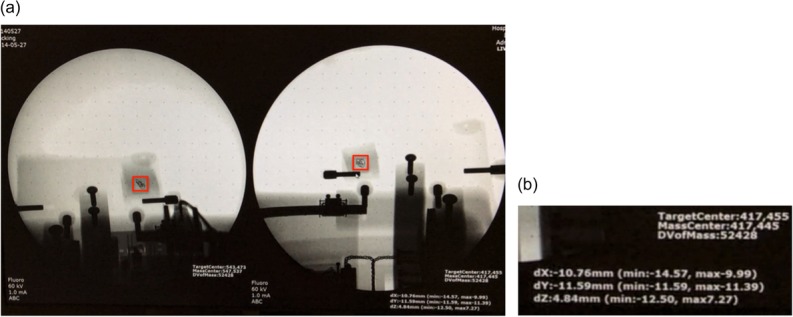
(a) A screen shot of the monitor when tracking with the G-arm fluoroscopy system. The fiducial marker at the center of the red rectangle was tracked by the system. (b) The 3D coordinates of the ROI in the current frame are illustrated on the monitor.
Fig. 3.
Determination of the 3D coordinates of a marker in biplane images. (The two blue circles represent biplane images of detectors A and B.)
The Vicon system
For external 1D surrogate tracking, the Vicon system composed of reflective markers, cameras, and data capturing software named Nexus [24] was used. The reflective markers are spheres covered with reflective material, and they were placed on visual reference points to be tracked by cameras. The Bonita 10 camera is one of the Vicon's small optical cameras that has high resolution (1024 × 1024 pixels) and a high frame rate (250 Hz).
After the calibration process, four Bonita 10 cameras were positioned to track the reflective markers. The captured data were transmitted to a computer through a Transmission Control Protocol/Internet Protocol (TCP/IP) socket. In the experiments, three reflective markers were used as external surrogates. Last, using the Vicon's data capture software ‘Nexus’ (this external marker tracking software is Vicon's product), the position of each exteranl marker in each frame was determined and exported to the coregistration program (described below). To verify the tracking accuracy of the Vicon system, the same moving phantom (BrainLAB) that was utilized for accuracy testing of the G-arm system was used.
4D phantom system
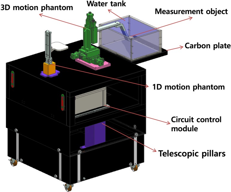
To assess the accuracy of the system we had developed, a 4D phantom system that could simultaneously imitate the patient's internal 3D motion and 1D abdominal motion was manufactured. Figure 4 shows the concept design of the 4D phantom system. The 1D motion phantom can be moved in the up and down direction to imitate patient abdominal motion. The 3D motion phantom can be moved along the 3D orthogonal coordinates with a millisecond time pitch in order to imitate tumor (‘target object’) motion. The water tank was designed to enable tracking in water, which has a similar density to a patient's body; it also provides dosimetry in water when necessary. The control module was used to direct the motors of the 1D and 3D phantoms.
Fig. 4.
The concept design of the 4D phantom system.
For motion management, an algorithm using Labview software (National Instruments, Austin, USA) was designed. The algorithm was used to import tumor motion data and Real-Time Position Management (RPM, Varian Medical System, Palo Alto, CA) data obtained from patient treatment. Through this algorithm, patients’ internal/external motion data were converted into 4D phantom motion derivers.
For simulating internal target motion, 10 phases from the 4D computed tomography (4DCT) scan data of five patients who had undergone liver cancer radiation therapy at our institution were analyzed. A radiation oncologist delineated an anatomical internal marker (a structure representing the tumor) in the liver in 10 respiratory phases of CT datasets and recorded the 3D coordinates of each internal marker. These 3D coordinates of the internal marker motion for one respiratory cycle were transferred to the control program of the 4D phantom, and identical motion for every respiratory cycle was assumed by repeating the motion.
For external surrogate motion, the RPM data from 4DCT scanning were employed. The RPM is composed of an infrared camera and a reflective plastic box, which is to be placed on the abdomen of the patient. The external marker is an infrared reflective circle attached to the face of the plastic box. The infrared camera records the location of the marker during the 4DCT scan and tags the data to the projected imaging data. The RPM trace data recorded for five patients from the CT scanner console were extracted and exported to the 4D phantom system's control program in order to move the 1D phantom, as shown in Fig. 4. Using the internal target motion data and external surrogate data obtained from the same patient, internal and external motions of five patients were reproduced in the 4D phantom system.
Coregistration of the internal/external tracking system
For real-time tracking of the internal target and external surrogate, the integration of the two independent systems is essential. Therefore, the G-arm and Vicon systems were integrated and synchronized—we named this process ‘Coregistration’. For the coregistration process, the coordinates of the three external markers were first measured by the Bonita cameras and imported to the Vicon system computer through a TCP/IP socket. Simultaneously, the internal marker coordinates data, captured with the G-arm system, were imported to the Vicon system computer through another TCP/IP socket. Therefore, the Vicon system computer simultaneously imported the data for the three external markers’ coordinates, together with data for the internal marker coordinates. An algorithm for monitoring the motion of these external and internal markers in real-time was developed and coded. In the code, the position data were recorded in a time pitch of 1/30 s following the imaging frame rate of the Vicon system. When integrating the position data from the G-arm system, where the frame rate was 28 frames/s, the received data from the G-arm system was assigned to the current Vicon time if the data-taking frame of the G-arm system was exactly synchronized with the Vicon system. Otherwise, the data from the G-arm was assigned to the next available Vicon frame time. Every position of one internal and three external markers were exported to an ASCII file for further retrospective analysis. Figure 5 depicts the machine set-up of the internal and external integrated tracking system drawn using 3D computer-aided design (CAD).
Fig. 5.
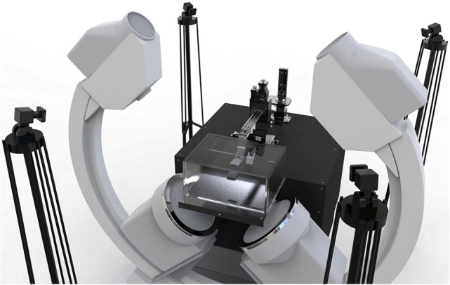
A 3D CAD drawing of the integrated tracking system and a 4D phantom. Four Bonita 10 cameras and the G-arm are shown in the figure.
RESULTS
Verifying each internal/external tracking component
Position accuracy test of each tracking component for sinusoidal motion
First, several tests were conducted to determine the accuracy of the position detected by each tracking system. A fiducial marker inserted into a 2 cm cubic bolus, which moves in the SI, AP and lateral direction upon the BrainLAB moving phantom with 20.0 mm, 15 mm and 10 mm peak-to-peak amplitude, was tracked by the G-arm system. Measurements were repeated three times under the same conditions in order to verify the reproducibility. The peak-to-peak amplitude was calculated as
| (3) |
using 3D coordinate data.
The output data of the internal marker tracking (G-arm) system are summarized in Table 1. The maximum value of the average error was 2.99%. In the clinical situation, that would be inside the acceptable margin of error.
Table 1.
The test results of the tracking accuracy of the G-arm system
| Measurement | |||||
|---|---|---|---|---|---|
| Phantom Movement | Exp. 1 (mm) | Exp. 2 (mm) | Exp. 3 (mm) | Average (mm) | Error (%) |
| x-axis 20 mm | 20.22 | 20.42 | 20.27 | 20.30 | 1.51 |
| x-axis 15 mm | 14.75 | 14.46 | 14.45 | 14.55 | 2.97 |
| x-axis 10 mm | 9.55 | 9.82 | 9.80 | 9.72 | 2.76 |
| y-axis 20 mm | 20.22 | 20.42 | 20.27 | 20.30 | 1.51 |
| y-axis 15 mm | 14.50 | 14.66 | 14.50 | 14.55 | 2.97 |
| y-axis 10 mm | 9.90 | 9.85 | 9.84 | 9.87 | 1.36 |
| z-axis 20 mm | 20.09 | 19.74 | 20.63 | 20.15 | 0.77 |
| z-axis 15 mm | 14.64 | 14.68 | 14.38 | 14.57 | 2.88 |
| z-axis 10 mm | 9.54 | 9.81 | 9.79 | 9.71 | 2.86 |
The BrainLAB phantom was moved in the SI, AP and LT directions at 20 mm, 15 mm and 10 mm amplitudes. The experiments were repeated three times.
For the same 20 mm, 15 mm and 10 mm peak-to-peak amplitude motion in the SI, AP and LT directions, tracking was conducted using the external marker tracking (Vicon) system, and the output data are summarized in Table 2. The maximum value of the average error was 2.13%. In the clinical situation, that would be inside the acceptable margin of error. The data presented in Tables 1 and 2 actually includes the system-specific error in detecting an object by both the internal and external marker tracking systems. The resultant error range gives the accuracy and precision level data when the developed system are applied for clinical cases.
Table 2.
The test results of the tracking accuracy of the Vicon system
| Measurement | |||||
|---|---|---|---|---|---|
| Phantom Movement | Exp. 1 (mm) | Exp. 2 (mm) | Exp. 3 (mm) | Average (mm) | Error (%) |
| x-axis 20 mm | 19.59 | 19.65 | 19.68 | 19.64 | 1.8 |
| x-axis 15 mm | 14.83 | 14.80 | 14.86 | 14.83 | 1.13 |
| x-axis 10 mm | 10.03 | 9.97 | 10.05 | 10.02 | 0.16 |
| y-axis 20 mm | 19.85 | 19.67 | 19.61 | 19.71 | 1.45 |
| y-axis 15 mm | 14.81 | 14.88 | 14.81 | 14.83 | 1.11 |
| y-axis 10 mm | 10.05 | 9.98 | 9.96 | 9.99 | 0.03 |
| z-axis 20 mm | 19.95 | 19.93 | 20.10 | 19.94 | 0.03 |
| z-axis 15 mm | 14.83 | 14.82 | 14.81 | 14.82 | 1.20 |
| z-axis 10 mm | 10.19 | 10.23 | 10.22 | 10.21 | 2.13 |
The BrainLAB phantom was moved in the SI, AP and LT directions at 20 mm, 15 mm and 10 mm amplitudes, and measured using the Vicon system.
Time delay test of the integrated system for sinusoidal motion
For the integration of the two independent tracking systems, the input time delay for each tracking system was measured. A fiducial marker that moves in the SI direction with a 20.0 mm peak-to-peak amplitude was simultaneously tracked using the coregistration system, and the output was recorded.
For data recording, as described in Section ‘Coregistration of the internal/external tracking system’, the position data were recorded for a time pitch of 1/30 s, following the imaging frame rate of the Vicon system. When the position data was integrated from the G-arm system, the G-arm data was assigned to the next available Vicon frame time if the time frame did not match the Vicon time frame. Therefore, the maximum deviation of the G-arm system was 1/30 s, which is the frame rate of the Vicon system. To verify the delay for the data from the G-arm system, AP motion was measured and is compared in Fig. 6. The time delay of the G-arm and Vicon systems was verified to be <1/30 s, which is also the time delay between ‘real phantom motion’ and the ‘measured internal marker tracker's output’.
Fig. 6.
The time delay test of the internal/external tracking system. (a) The red line represents the Vicon system's output signal tracking AP motion, and the blue line represents the G-arm system's output signal. (b) A magnified picture of the first peak in (a). The time difference between the two first peaks is 1/30 s.
System latency of internal marker tracker
In the clinical situation, the time delay between ‘real organ motion’ and the internal marker tracker's output is critical. The system latency of the internal marker tracker is defined in this section. In the official brochure [25], the system latency of the external marker tracker is defined as 2 ms. In the previous section (Time delay test of the integrated system for sinusoidal motion), a fiducial marker was simultaneously tracked with the internal marker tracker and the external marker tracker. Therefore, the system delay between ‘real motion’ and the internal marker tracker's output is the sum of the time delay between the internal/external marker tracker (1/30 s) and the external marker tracker's system delay time (2 ms). Therefore, the system latency of the internal marker tracker is computed as 5.33 ms.
Verifying the integrated system
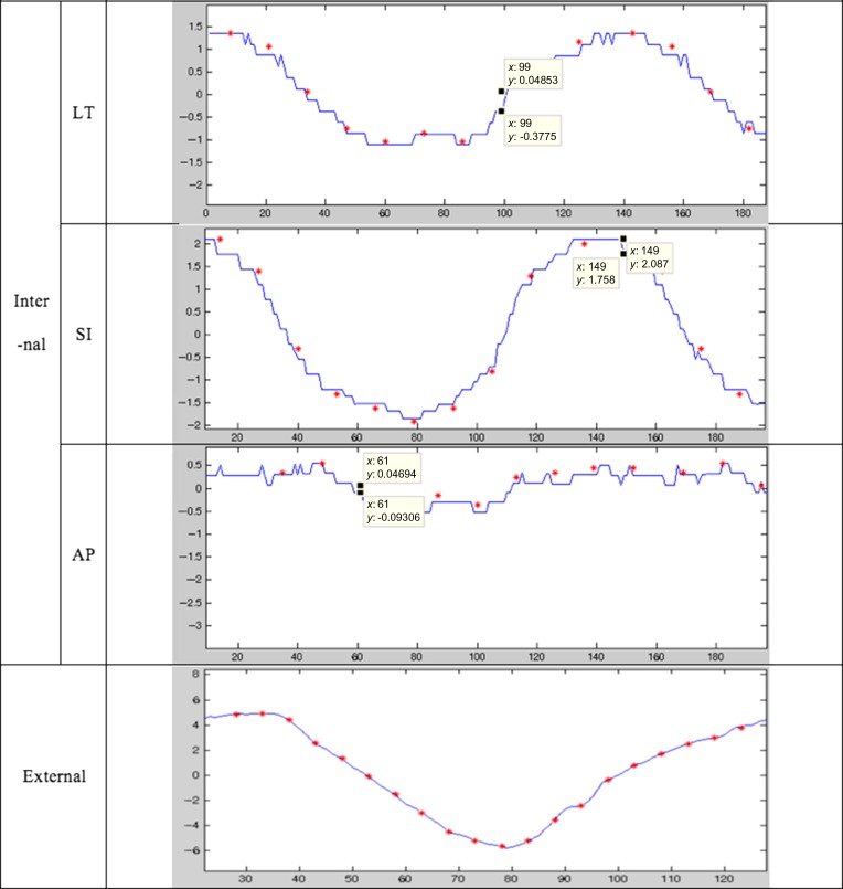
The test results of the integrated system using five patients’ motion data are summarized in Fig. 7 and Fig. 8. Figure 7 shows the internal marker motion profile in LT, SI and AP directions and the output data of the integrated system. In the figure, the red dots represent the input signal (i.e. the patients’ internal marker movement), and the blue line represents the measured signal of the tracking system. The correlation analysis between the marker motion amplitude and the tracker output amplitude was conducted in order to verify how accurately the tracking system can track the internal marker motion. The results for each coefficient ranged from 0.89 to 0.99. Except for two cases (AP motion of Patient 1, and lateral motion of Patient 3), the correlation coefficients were > 0.94. The standard deviation of the differences between the input signals and the measured values are also presented in order to show the characteristics of the detectors. Every value for the standard deviation was <0.4. This result shows the reliable stability of this system.
Fig. 7.
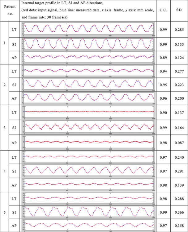
Motion tracking analysis in the G-arm system. Internal target profile in LT, SI and AP directions. The red dots are input signals and the blue line represents measured data. The x-axis is the frame, and the y-axis is the displacement of the target in millimeters. In the experiment, the frame rate of the detection was 30 frames/s. The correlation coefficients and standard deviations of the differences between the input signals and the measured values were also measured.
Fig. 8.
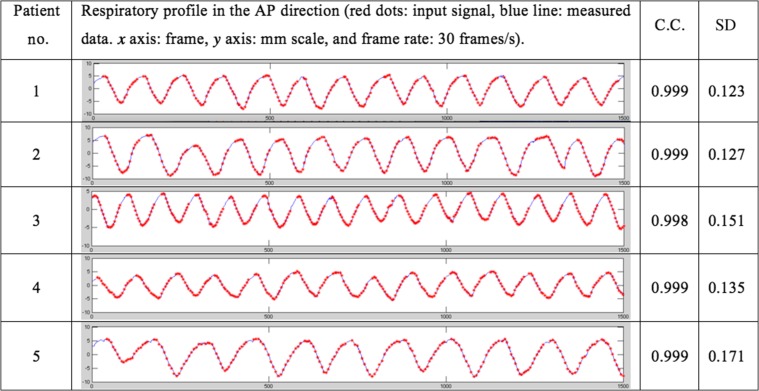
Motion tracking analysis in the Vicon system. The red dots are input signals, and the blue lines represent measured data. The x-axis is frame, and y-axis is displacement of the target in millimeters. In the experiment, the frame rate of the detection was 30 frames/s. The correlation coefficients and standard deviations of the differences between the input signals and the measured values were also measured.
Figure 8 represents the external marker motion in the AP direction and the output data of the integrated tracking system. Correlation analysis between the external marker motion and the tracker output was also conducted. Comparison with the input data showed that the integrated tracking system had reasonable accuracy, with correlation coefficients ranging from 0.998 to 0.999.
For easier reading of the graph, Fig. 9 shows the enlarged first breath cycle of Patient 1. Through this figure, the difference between the input signals and the measured values are more easily observable. The external marker tracking system's accuracy was very high, hardly showing a gap between the input signal and the measured value.
Fig. 9.
Patient no. 1’s first breath cycle and the associated data measured through the internal/external marker tracker. Red dots: input signal; blue line: measured data; x-axis: frame; ‘y-axis: mm scale; frame rate: 30 frames/s.
DISCUSSION
Respiratory motion has critical effects on particle therapy. Respiratory gating is one solution for active management of respiratory motion. Through the aid of an external or internal marker tracking system, delivery of radiation to a specific portion of the respiratory cycle can be realized. Currently, external surrogate–based gating or internal marker–based gating is available in particle therapy but combined monitoring of the internal/external target during particle therapy is not commercially available. In the clinical situation, verification of the internal tumor target position in relation to the external marker motion is essential. To this end, a system was designed that combines an internal tracking system and an external tracking system, with verification via several methods.
In this study, we designed a G-arm fluoroscopy system that simultaneously shows AP and LT views, and used image intensifiers as detectors. There were two options for detectors: image intensifiers or flat panel detectors. X-ray flat panel detectors have a wider field of view and less distortion. However, they have a limited frame rate, and cost is high. Also, the distortion of image intensifiers is negligible in the center region (~500 × 500 pixel circle). Therefore, we selected image intensifiers as our detectors. For minimizing the calculation error, we also used a distortion correction algorithm.
Our results verified the position accuracy and timing delay for this system. First, the position accuracy test was verified for each tracking system. This experiment was needed in order to determine the reliability of the tracking system. A fiducial marker, which move in 20 mm, 15 mm and 10 mm peak-to-peak sinusoidal 1D motion in the AP, SI and LT direction upon the brainLAB moving phantom, was tracked by the internal and external marker tracking systems. Tables 1 and 2 show that the tracking accuracy of each internal and external marker tracking system was <2.99% at the millimeter scale. In the clinical situation, this could be regarded as falling inside acceptable accuracy. Second, the integrated system's time delay was tested. If there is significant time delay between each internal/external tracking system, this could be lead to serious uncertainty in the radiation therapy. Therefore, a marker that moves in the SI direction with a 20.0 mm peak-to-peak amplitude was simultaneously tracked by the coregistration system, and the output was recorded. Figure 6 shows that the time delay of the internal and external marker tracking systems is < 1/30 s, which could be regarded as lying inside the acceptable timing delay. The observed time delay between the internal marker tracker and the external marker tracker was caused by the different frame rates of data-taking in the G-arm system and the Vicon system. In our experiments, the frame rate of the Vicon system was set to be 30 frames/s, which is similar to that of the G-arm system. However, if the frame rate of the Vicon system was increased, the observed time delay of the G-arm system would be reduced.
Finally, a phantom study using patients’ internal marker motion data and RPM data was conducted. For simulating internal target motion, 10 phases from the 4DCT scan data of five patients who had undergone liver cancer radiation therapy at our institution were analyzed. Based on the reference article [16, 26], the images are reconstructed to produce at least 10 CT images that can be binned into 10 phases covering the entire breathing cycle. Actually, the required breathing cycle depends on the breathing pattern of the patients, but we trained the patients until they could breath regularly. Therefore, 10 breathing cycles were enough for our simulation. Through the phantom study, we were able to verify that this coregistration system can track the internal and external markers accurately and quickly.
All of the results presented in this study were obtained to test the acceptability of the coregistration tracking system before integrating it into the proton therapy system at our site. This verified coregistration tracking system will be merged into the proton therapy system in the near future and studied further.
As mentioned above, in most cases, external surrogates were used for treating moving targets with breath holding or gating technique. In determining the PTV, an additional treatment margin is applied to account for the inconsistency between the tumor position and the external surrogate position. The ideal solution for this problem is internal marker tracking that accurately indicates the tumor position. Recently, ‘Hitachi’ has been working on the development of a real-time tumor-tracking proton therapy system with Hokkaido University, and it is now available for clinical use. However, the extra imaging dose caused by internal marker tracking can be critical for the normal tissue of the patient [27]. Therefore, intermittent internal marker position verification with X-ray imagers, together with external marker tracking, was designed—i.e. a hybrid system. The advantage of this hybrid system is that the relative weight attributed between the external surrogate information and the internal marker information can be decided according to each patient's characteristics. Therefore, the hybrid system can achieve a dose reduction to normal tissue (through minimizing the PTV and the imaging dose for internal marker tracking) in comparison with the current tracking system, which tracks either the internal or external marker only.
CONCLUSIONS
We designed an internal and external marker tracking system using a biplane orthogonal X-ray imager (G-arm) and a high-performance camera system (Vicon). Integration of both tracking systems was needed for simultaneous monitoring of the internal targets and the external surrogates of patients who were undergoing proton therapy. The experimental results for the internal and external marker tracking systems showed acceptable accuracy in position detection for both internal and external trackers.
As for applicability, the developed system itself can be used if a biplane G-arm and Vicon hardware arrangement is feasible in a treatment room. In our proton therapy system, we are currently interfacing the developed tracking software to allow internal marker tracking with the images from a biplane flat-panel digital X-ray detector, while using the Vicon system to monitor external surrogates. Shimizu et al. previously proposed a simulation study of real-time image-gated proton therapy [28]. However, they only considered internal marker tracking. Our simulation study involved an integrated internal/external system, which would contribute to dose reduction to normal tissues. This system will be available for clinical use for particle therapy in a few years’ time.
FUNDING
This research was supported by the National Research Foundation of Korea (NRF) funded by The Ministry of Science, ICT & Future Planning (Nos 2012M3A9B6055201 and 2012R1A1A2042414) and by a grant from Samsung Medical Center (No. GFO1130081).
REFERENCES
- 1. Gierga DP, Brewer J, Sharp GC, et al. . The correlation between internal and external markers for abdominal tumors: implications for respiratory gating. Int J Radiat Oncol Biol Phys 2005;61:l551–8. [DOI] [PubMed] [Google Scholar]
- 2. Plathow C, Ley S, Fink C, et al. . Analysis of intrathoracic tumor mobility during whole breathing cycle by dynamic MRI. Int J Radiat Oncol Biol Phys 2004;59:952–9. [DOI] [PubMed] [Google Scholar]
- 3. Keall PJ, Joshi S, Vedam SS, et al. . Four-dimensional radiotherapy planning for DMLC-based respiratory motion tracking. Med Phys 2005;32:942–51. [DOI] [PubMed] [Google Scholar]
- 4. Tsunashima Y, Sakae T, Shioyama Y, et al. . Correlation between the respiratory waveform measured using a respiratory sensor and 3D tumor motion in gated radiotherapy. Int J Radiat Oncol Biol Phys 2004;60:951–8. [DOI] [PubMed] [Google Scholar]
- 5. Iwasawa T, Yoshiike Y, Saito K, et al. . Paradoxical motion of the hemidiaphragm in patients with emphysema. J Thorac Imaging 2000;l5:191–5. [DOI] [PubMed] [Google Scholar]
- 6. Matsuo Y, Onishi H, Nakagawa K, et al. . Guidelines for respiratory management in radiation therapy. J Radiat Res 2013;54:561–8. [DOI] [PMC free article] [PubMed] [Google Scholar]
- 7. Kubo HD, Hill BC. Respiration gated radiotherapy treatment: a technical study. Phys Med Biol 1996;41:83–91. [DOI] [PubMed] [Google Scholar]
- 8. Kubo HD, Wang L. Compatibility of Varian 2100C gated operations with enhanced dynamic wedge and IMRT dose delivery. Med Phys 2000;27:1732–8. [DOI] [PubMed] [Google Scholar]
- 9. Shirato H, Shimizu S, Kunieda T, et al. . Physical aspects of a real-time tumor-tracking system for gated radiotherapy. Int J Radiat Oncol Biol Phys 2000;51:304–10. [DOI] [PubMed] [Google Scholar]
- 10. Papiez L, Rangaraj D. DMLC leaf-pair optimal control for mobile, deforming target. Med Phys 2005;32:275–85. [DOI] [PubMed] [Google Scholar]
- 11. Baroni G, Riboldi M, Spadea MF, et al. . Integration of enhanced optical tracking techniques and imaging in IGRT. J Radiat Res 2007;48:A61–74. [DOI] [PubMed] [Google Scholar]
- 12. Desplanques M, Tagaste B, Fontana G, et al. . A comparative study between the imaging system and the optical tracking system in proton therapy at CNAO. J Radiat Res 2013;54:i129–35. [DOI] [PMC free article] [PubMed] [Google Scholar]
- 13. Yan H, Yin FF, Zhu GP, et al. . Adaptive prediction of internal target motion using external marker motion: a technical study. Phys Med Biol 2005;51:31–44. [DOI] [PubMed] [Google Scholar]
- 14. Ionascu D, Jiang SB, Nishioka S, et al. . Internal–external correlation investigations of respiratory induced motion of lung tumors. Med Phys 2006;34:3893–903. [DOI] [PubMed] [Google Scholar]
- 15. Kanoulas E, Aslam JA, Sharp GC, et al. . Derivation of the tumor position from external respiratory surrogates with periodical updating of the internal/external correlation. Phys Med Biol 2007;52:5443–56. [DOI] [PubMed] [Google Scholar]
- 16. Beddar AS, Kainz K, Briere TM, et al. . Correlation between internal fiducial tumor motion and external marker motion for liver tumors imaged with 4D-CT. Int J Radiat Oncol Biol Phys 2007;67:630–8. [DOI] [PubMed] [Google Scholar]
- 17. Ionascu D, Jiang SB, Nishioka S, et al. . Internal–external correlation investigations of respiratory induced motion of lung tumors. Med Phys 2007;34:3893–903. [DOI] [PubMed] [Google Scholar]
- 18. Yan H, Zhu G, Yang J, et al. . Investigation of the location effect of external markers in respiratory-gated radiotherapy. J Appl Clin Med Phys 2008;9:57–68. [DOI] [PMC free article] [PubMed] [Google Scholar]
- 19. Hoisak JDP, Sixel KE, Tirona R, et al. . Prediction of lung tumour position based on spirometry and on abdominal displacement accuracy and reproducibility. Radiother Oncol 2006;78:339–46. [DOI] [PubMed] [Google Scholar]
- 20. Masumi U, Futaro E, Yusuke F, et al. . Development of compact proton beam therapy system for moving organs. Hitachi Rev 2015;64:506–13. [Google Scholar]
- 21. Strobel N, Meissner O, Boese J, et al. . 3D Imaging with Flat-Detector C-Arm Systems. 3rd edn.Berlin Heidelberg: Springer, 2009, 33–51. [Google Scholar]
- 22. Pluim JPW, Maintz JBA, Viergever MA. Image registration by maximization of combined mutual information and gradient information. IEEE Trans Med Imaging 2000;19:809–14. [DOI] [PubMed] [Google Scholar]
- 23. Pluim JP, Maintz JBA, Viergever MA. Mutual information based registration of medical images: a survey. IEEE Trans Med Imaging 2003;22:986–1004. [DOI] [PubMed] [Google Scholar]
- 24. Woolard A. Vicon 512 User Manual. Tustin CA: Vicon Motion Systems, 1999. [Google Scholar]
- 25. Vicon Motion Systems Ltd Bonita, UK. http://www.virtalis.com/wp-content/uploads/bonita.pdf.
- 26. Melinda PC, Balter P, Luo D, et al. . Relation of external surface to internal tumor motion studied with cine CT. Med Phys 2006;33:3116–23. [DOI] [PubMed] [Google Scholar]
- 27. Shirato H, Oita M, Fujita K, et al. . Feasibility of synchronization of real-time tumor-tracking radiotherapy and intensity-modulated radiotherapy from viewpoint of excessive dose from fluoroscopy. Int J Radiat Oncol Biol Phys 2004;60:335–41. [DOI] [PubMed] [Google Scholar]
- 28. Shimizu S, Miyamoto N, Matsuura T, et al. . A proton beam therapy system dedicated to spot-scanning increases accuracy with moving tumors by real-time imaging and gating and reduces equipment size. PLoS One 2014;9:e94971. [DOI] [PMC free article] [PubMed] [Google Scholar]


