

Abstract
The viability and differentiation of SaOS-2 preosteoblasts on fiber mats of blends comprising of the biodegradable poly(ester-ether) polydioxanone (PDX) and the sulfate-containing anionic polysaccharides kappa-carrageenan (KCG) and fucoidan (FUC) were investigated for a range of different blend compositions. The detailed analysis of the blend nanofiber properties revealed a different degree of miscibility of PDX and the polysaccharide leading to a different enrichment at the surface of the blend nanofibers, which were observed to be stable in phosphate buffer solution (PBS) for up to 5 weeks. The fibrous mats of PDX/FUC led to the highest osteogenic differentiation with very good cell viability. The electrospun blend fibers also supported human-induced pluripotent stem (iPS) cells and iPS cell-derived embryoid bodies with high cell viability, which underlines the potential of these novel blend fiber systems for optimized performance in bone tissue engineering applications.
Keywords: anionic polysaccharides, electrospun fibers, cell viability, osteogenic differentiation, iPS cell-derived embryoid bodies
Introduction
Healthy bone has the natural ability to heal spontaneously.1 However, the use of bone grafts cannot be avoided, e.g., for patients suffering from traumatic accidents or genetic defects.2 Common bone grafts such as autografts (patient bone), allografts (human cadaver bone), xenografts (animal bone), and synthetic materials (ceramics and metals), which are used to supplement bone repair in large defects, are associated with several limitations, including donor site morbidity, limited availability, risk of infections, and disease transmission.3,4 As a result, there has been growing interest in the creation of new bone by culturing the patient̀s own cells on a scaffold in physiological conditions (bone tissue engineering, BTE). To engineer an environment supporting bone formation, combinations of biochemical and biophysical cues need to be presented to the cells in a three-dimensional setting in a way that enables cellular interactions with the surrounding cells and the extracellular matrix (ECM).5 In this context, micromechanical interactions between the cells and the scaffolds have to be considered as well since these influence both cell migration and differentiation.6 The cells also exert forces on the scaffold and can remodel it throughout tissue development.
The clinical and scientific utility of tissue engineering largely depends on the ability to predictably induce the differentiation of cells into the correct phenotypes in a spatially and temporally defined pattern. As shown in several studies, cellular differentiation can be greatly influenced by the surrounding cell microenvironment, highlighting the importance of careful scaffold design and processing.7−9 Among other scaffold processing techniques, electrospinning has often been lauded due to its potential to fabricate ECM mimicking fibers.10−12 Furthermore, electrospun materials are multifunctional as they allow the incorporation of ligands for integrin binding, glucosaminoglycans representing ECM proteoglycans, growth factors that stimulate cell growth and differentiation, and drugs that can be used to suppress adverse body reactions.13
Usually more than one polymeric material is required to achieve the desired properties in a given scaffold. A promising strategy is the use of polymer blends, which combine good mechanical properties and biodegradability, afforded e.g. by a synthetic polyester on the one hand with advantageous surface properties afforded by natural biopolymers on the other hand. Compared to the individual synthetic and natural polymers, their blends have been reported to result in improved in vitro apatite formation,14 enhanced cell proliferation, and differentiation.15 Natural polymers possess organized structures, which can bind with cell receptors, leading to good cell attachment and proliferation.16 In line with this, we recently reported that the incorporation of the anionic sulfated polysaccharides kappa-carrageenan (KCG) and fucoidan (FUC) into polyhydroxybutyrate (PHB) and poly(hydroxybutyrate-valerate) (PHBV) resulted in enhanced bioresponse with a concomitant overall decrease in crystallinity, enhancement of surface hydrophilicity, reduction in brittleness, and faster degradation of the polymer blend films.17
Following these promising results, electrospun PHB/KCG and PHBV/KCG fibers were investigated.18 The presence of KCG at the blend fiber surface resulted in the formation of nanosized apatite crystals compared to micron-sized ones formed on the surface of the pure polyesters. Well-developed filopodia from mouse fibroblast cells were observed on the surface of the blend fibers, which facilitated cell proliferation. In addition, KCG incorporation in PHB and PHBV fibers resulted in improved in vitro differentiation and mineralization of preosteoblasts (SaOS-2).18
The structure of KCG closely resembles that of natural glycosaminoglycans (GAGs) present in the native ECM.19 Furthermore, its inherent thixotropic behavior facilitates its use as an injectable matrix for the delivery of macromolecules and cells.20 Both KCG21 and FUC22 have been shown before to be promising for BTE applications. FUC has been reported to increase the cellular activity of bone by inducing fibroblasts growth factor-2, collagen formation, fibroblastic proliferation and in vitro and in vivo angiogenesis.23,24 However, despite encouraging results of KCG and FUC, there are still major shortcomings, which need to be addressed. These include, for instance, expensive price and difficulties in the processability of electrospun scaffold in clinical applications.
In this current study we expand on the promising initial results mentioned above by investigating and determining the impact of (i) the type of natural biopolymer (kappa-carrageenan, KCG vs fucoidan, FUC) and (ii) a different synthetic polymer (polydioxanone, PDX) on the cell viability and differentiation.
Polydioxanone (PDX) was chosen due to numerous attractive properties as the biodegradable polyester for the blend fibers. PDX has not received much attention except for a few applications since its commercialization in 1981.25−27 However, this poly(ester-ether) possesses considerable potential for biomedical applications due to its good mechanical performance, biocompatibility and biodegradability.28 PDX shows greater softness and flexibility (Young’s modulus = 15 MPa) compared to polyesters, such as PHB (Young’s modulus = 275 MPa), due to the presence of the ether bond and the additional methylene group.29,30 In addition, the mechanical properties of electrospun PDX are of the same order of magnitude as the major structural components of native ECM (including bone ECM). In particular the peak stress exhibited by electrospun PDX is within the range of elastin and near the lower limit of collagen.30 Furthermore, several studies showed promising initial results of PDX in BTE applications.31−34
The aim of this current study was to investigate how cell viability and differentiation are affected by the incorporation of KCG or FUC in electrospun PDX blend fiber mats. The properties of electrospun fibers consisting of blends of KCG or FUC with PDX were analyzed and the response, morphology and promotion of osteogenic differentiation of SaOS-2 preosteoblasts were unraveled. In addition, the cell viability of NIH3T3 fibroblasts and induced pluripotent stem (iPS) cells was analyzed on the various blend fiber mats. NIH3T3 cell proliferation was found to be significantly improved on PDX/KCG scaffold materials compared to PHB/KCG and PHBV/KCG fibers, whereas the osteogenic differentiation data indicated a higher innate osteogenic differentiation potential of PDX/FUC compared to PDX/KCG scaffold materials, all of which is promising for optimized blend fiber performance in BTE applications.
Experimental Section
Materials
Polydioxanone (Resomer X 206S, inherent viscosity 2.0, Mw = 1.01 × 10⁵ g/mol) was purchased from Evonik, Germany. KCG and FUC were bought from Sigma-Aldrich. 1,1,1,3,3,3-hexafluoroisopropanol (HFIP) purchased from FluoroChem, was used as received. The Milli-Q water used in this study was drawn from a Millipore Direct Q8 system (Millipore, Schwalbach, with Millimark Express 40 filter, Merck, Germany) with a resistivity of 18.0 MΩ cm. Phosphate buffer tablets (PBS) were purchased from VWR Life Sciences and PBS solution was prepared by dissolving one tablet in 100 mL of Milli-Q water.
Electrospinning
PDX/KCG blend solutions at a concentration of 150 mg/mL were prepared by dissolving PDX and KCG in HFIP and CHCl3, respectively. Similarly, PDX/FUC blend solutions with a concentration of 175 mg/mL were prepared by dissolving PDX and FUC in HFIP and DMF, respectively. The blend solutions were stirred at 300 rpm for 1 h at room temperature. The solvent ratio varied depending on the blend system as summarized in Table 1. PDX/KCG and PDX/FUC were blended in the following ratios: 100/0, 90/10, 80/20 and 70/30 w/w% and all polymer blend solutions were left on a shaker plate overnight before electrospinning. Electrospinning was carried out using the same set up as reported by Goonoo et al.18 The electrospinning parameters (Table 1) were optimized to produce continuous fibers, which were collected as nonwoven fiber mats on the statically grounded rectangular aluminum target. After electrospinning, the mats were removed from the collecting target and stored in a desiccation chamber until further analysis.
Table 1. Electrospinning Parameters Used for PDX/KCG and PDX/FUC Solutions.
| blend system | solvent system | concentration (mg/mL) | flow rate (mL/h) | voltage (kV) | air-gap distance (cm) |
|---|---|---|---|---|---|
| PDX/KCG | HFIP/CHCl3 (7/3 v/v) | 150 | 6.0 | +25 | 15 |
| PDX/FUC | HFIP/DMF (9/1 v/v) | 175 | 0.3 | +20 | 15 |
Characterization of Electrospun Mats
The average fiber diameter of the electrospun mats was determined as reported in Goonoo et al.18 by scanning electron microscopy. Briefly, the average fiber diameter was determined by measuring the diameter of 50 different fibers from scanning electron microscopy (SEM) images using ImageJ software. The SEM images and high resolution field-emission (FE)-SEM images were taken using a CamScan microscope (CS24, USA) and a Quanta 450 field-emission-scanning electron microscope respectively, as reported previously.18
Attenuated Total Reflectance-Fourier Transform Infra-Red (ATR-FTIR) spectra were recorded using a Bruker Tensor 27. ATR-FTIR spectra were acquired between 600 and 3500 cm–1 by accumulating 16 scans.
The thermal properties of the electrospun blend fibers were analyzed using a differential scanning calorimetry (DSC) and a thermogravimetric analyzer (TGA) as reported in Goonoo et al.18 The degree of crystallinity of PDX in the blend mats (XPDX) was calculated using eqs 1–3. For that purpose, the enthalpy of melting for 100% crystalline PDX was taken from the literature as 141.18 J/g.
| 1 |
| 2 |
| 3 |
The static contact angles of the fiber mats were measured using Milli-Q water as a probe liquid with an OCA 15plus instrument (Data Physics Instruments GmbH, Germany), as also reported previously.18 Measurements were taken for at least three independent samples for all characterizations.
Fiber morphology and integrity of the electrospun mats was assessed using PBS (pH 7.3) at 37 °C for up to 5 weeks.18
Culture of NIH3T3 Mouse Fibroblast Cells and SaOS-2 Preosteoblast Cells
The NIH3T3 and SaOS-2 cells were cultured at standard conditions (37 °C, 5% CO2) as reported earlier.18 The MTT assay was conducted to quantify the number of NIH3T3 cells on the blend mats on days 3 and 7, respectively.18 The ability for mineralized nodule formation and calcium deposition by SaOS-2 cells (mineralization) was investigated via Alizarin Red-S staining.18
Live–Dead Staining
Triplicates of 1 × 1 cm2 of each blend mat were disinfected (30 min ethanol followed by three 10 min PBS washes) and transferred to 24-well plates and seeded with 100 000 NIH3T3 or 1 00 000 SaOS-2 cells/well or with embryoid bodies (see Section 2.5). Cell viability was assessed after 24 h via live–dead assay whereby cells were stained with FDA (5 mg/mL, Fluorescein diacetate; Sigma-Aldrich) and PI (2 mg/mL, Propidium Iodide; Carl Roth), respectively. Fluorescence microscopy images of live (green) and dead (red) cells were then acquired with a fluorescence microscope (Axiovert 135, Carl Zeiss, Oberkochen, Germany). The number of live cells (green) and dead cells (red) were then quantified from fluorescence images.
Fluorescence-Staining of SaOS-2 Cells
For fluorescence staining, the cells were washed with PBS, fixed with paraformaldehyde (4% in PBS, 30 min; VWR), permeabilized with Triton X-100 (0.2% in PBS, 10 min; VWR), and unspecific binding sides were blocked for 45 min (2% BSA in PBS; Sigma-Aldrich) at room temperature. Samples were incubated in a phalloidin–rhodamine solution for 30 min (5 U/mL in 1% BSA; Invitrogen, Life Technologies) as well as Hoechst staining solution (Sigma-Aldrich) for 20 min. Samples were mounted with Mowiol mounting medium (Carl Roth GmbH) on cover glass slides and attached to microscope slides.
Induced Pluripotent Stem Cell (iPSC) Culture
Human dermal fibroblast-derived (feeder-free) iPSCs were bought from BioCat GmbH (Heidelberg, Germany). They were cultured on Matrigel (Corning hESC-Matrix) coated TCPS 6-well plates and the iPSC colonies were maintained in mTeSR1 medium (Stem Cell Technologies). The medium was replaced every day and the iPSC colonies were passaged every 5–6 days. Briefly, the cell colonies were first washed with PBS and the colonies incubated with 1 mL of ReLeSR (enzyme-free treatment) for 5 min. After incubation, 1 mL of mTeSR1 was added and the colonies were detached by firmly tapping the side of the plate for about 30–60 s. The detached cell aggregates were transferred to a 15 mL of falcon tube and centrifuged (300 g, 3 min). The cell aggregates were resuspended in fresh mTeSR1 using a 5 mL serological pipet (so as not to destroy the aggregates) and then plated at the desired density (1:6) onto precoated Matrigel wells containing mTeSR1. The plate was moved back-and-forth and side-to-side to ensure even cell distribution and then incubated at 37 °C.
Embryoid Body (EB) Formation Using the Hanging Drop Method
The hanging drop method provides uniform sizes of EBs by dispensing equal numbers of iPS cells in physically separated droplets of media suspended from the lid of a Petri-dish. For EB formation, single cells were obtained from iPSC colonies by incubating the colonies with 500 μL of Accutase (Merck Millipore, Darmstadt, Germany) for 5 min at 37 °C. After incubation, 1 mL of medium (1:1000 v/v mTeSR1: inhibitor Y-27632 (Stem Cell Technologies)) was added to each well and the contents transferred to a 15 mL falcon tube and centrifuged at 1200 rpm for 4 min. After centrifugation, the supernatant was removed and the cell pellet was resuspended in fresh medium. The number of cells was counted using a Neubauer improved counting chamber (Brand, Wertheim, Germany). A diluted cell suspension was prepared with final concentration 75 cells/μL.
As a next step, 10 mL of PBS was added to 10 cm Petri-dishes. With the help of a multichannel pipet, 20 μL (1 drop) of the diluted cell suspension (1500 cells) were deposited onto the lid of the Petri-dish. The lid of the Petri dish was very carefully and quickly inverted onto the Petri dish. The Petri dish was then incubated at 37 °C for 24 h.
Seeding of EBs on Electrospun Mats
After 24 h incubation at 37 °C, the EBs were flushed with 5 mL mTeSR1 of and then transferred to a Petri-dish. The number of EBs was counted using the optical microscope (Primovert, Carl Zeiss, Oberkochen, Germany). Prior to seeding of EBs onto the scaffold materials, the latter were immersed overnight in 70% ethanol (asceptic agent) and incubated with 10 μg/mL Fibronectin (Bovine plasma, Calbiochem, EMD Millipore Corp USA) at 37 °C for 1 h. Approximately 20 EBs were seeded on each electrospun mat (1 × 1 cm2) and 1 mL mTeSR1 was added to each well (24-well plate).
Statistical Analysis
The data are presented as mean ± standard error of mean. Statistical analyses were done with the one-way analysis of variance (ANOVA) test (Origin Software Version 8.5) except where indicated and a Bonferroni post-test was used. A value of p < 0.05 was considered statistically significant.
Results and Discussion
Fabrication and Characterization of PDX/Polysaccharide Blend Fibers
Blend fibers consisting of PDX and the polysaccharides KCG or FUC were fabricated using the electrospinning method. For electrospinning, solutions of PDX/KCG or PDX/FUC in HFIP mixed with CHCl3 or DMF, respectively, were employed (Table 1). The polymer blend ratio was varied to investigate different ECM mimicking biochemistries and mechanical strengths. However, due to the ionic nature of the polysaccharides and their ability to form strong intramolecular hydrogen bonds, they cannot be electrospun from neat polysaccharide solution or at high polysaccharide/PDX ratios. Hence in this study, the blend ratio was varied from 100/0 to 70/30; 30% (w/w) was the highest polysaccharide content in the blend fibers. All further studies were conducted with this polysaccharide content. The resulting electrospun blend fiber mats were analyzed by SEM and FE-SEM to confirm the bead-free fiber morphology (Figure 1). Fiber diameters ranged between 0.50–1.15 μm and 0.24–0.33 μm for PDX/KCG and PDX/FUC fibers respectively (Table 2).
Figure 1.

SEM images of electrospun 70/30 (A) PDX/KCG and (B) PDX/FUC; FE-SEM images of (C) PDX/KCG 100/0, (D) PDX/KCG 70/30, and (E) PDX/FUC 70/30 fibers.
Table 2. Summary of Fiber Diameters According To SEM Data.
| blend composition | fiber diameter (μm) |
|---|---|
| PDX/KCG | |
| 100/0 | 1.15 ± 0.27 |
| 90/10 | 1.00 ± 0.22 |
| 80/20 | 0.87 ± 0.22 |
| 70/30 | 0.50 ± 0.19 |
| PDX/FUC | |
| 100/0 | 0.39 ± 0.10 |
| 90/10 | 0.20 ± 0.07 |
| 80/20 | 0.21 ± 0.05 |
| 70/30 | 0.24 ± 0.05 |
The presence of physical interactions between PDX and the polysaccharides was investigated by ATR-FTIR spectroscopy of the blend fibers. Pure PDX fibers showed a strong and characteristic peak of the carbonyl C=O stretching vibration at 1735 cm–1 and a smaller peak associated with the C–H stretching vibration at 2968 cm–1. The broad peaks at around 3381 cm–1 in both KCG and FUC were attributed to the O–H stretching vibration. In addition, the FTIR spectrum of KCG showed a characteristic O=S=O asymmetric stretching and the C–O–C stretching vibration of the 3,6 anhydrogalactose at 1222 and 923 cm–1, respectively.35 The bands in the region of 840–850 cm–1 in KCG were attributed to the presence of the C–O–SO3– group on C4 of the 3-linked β-d-galactopyranosyl unit.36 FUC displayed a broad band at 1183–1280 cm–1 with a maximum at 1216 cm–1 (S–O stretching vibration). The broad band at 830 cm–1 (C–S–O) in FUC suggests a complex pattern of substitution according to Rodriguez-Jasso et al.37 The carbonyl region, which is sensitive to H-bonding, was analyzed in depth, because noncovalent interactions between PDX and the polysaccharides were anticipated. From the FTIR spectra, no shifts in the position of the carbonyl peaks were observed for the blend fibers in comparison to pure PDX (Figure 2). The analysis of the second derivative spectra of pure PDX showed that the C=O peak consists of two components centered at 1734 and 1746 cm–1. This splitting has been attributed in the literature to the “cis” and “trans” conformations of the oxyethanoate structure (−O–CH2–CO-O−) in PDX.38 The presence of a new peak in the second derivative spectrum of PDX/KCG was noted at 1719 cm–1, which was absent in the spectra of the corresponding PDX/FUC blend fibers (Figure 3). This suggests that the C=O groups in PDX are involved in the formation of H-bonding with the OH groups in KCG. In general, C=O bands in the region 1700–1720 cm–1 are well-known for many H-bonded polymers containing C=O groups and OH groups.39,40 The peak at 1747 cm–1 can be assigned to “free” trans C=O groups; the intermediate peak (1734 cm–1) resulted from the overlap of “free” cis C=O groups and H-bonded trans C=O groups. The peak at 1719 cm–1 was attributed to H-bonded cis C=O groups. The red shifts observed for both the trans and cis C=O groups are nearly identical, about 16 cm–1.
Figure 2.
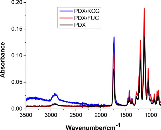
FTIR spectra of PDX, PDX/KCG 70/30, and PDX/FUC 70/30.
Figure 3.
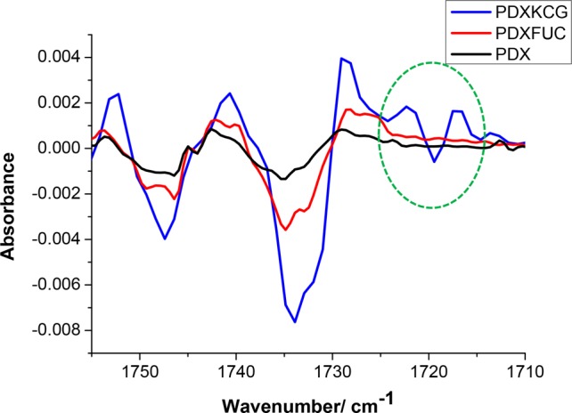
Second derivative FTIR spectra of PDX and 70/30 blend fibers.
Further evidence for noncovalent interactions in the blend fibers was sought from differential scanning calorimetry (DSC) and thermogravimetric analyses (TGA). Phase separation of the two polymers in the blends was studied by observing changes in the melting temperature (Tm). The observation of only one Tm for the 90/10 PDX/KCG fibers, which was lower than that of PDX, indicates the miscibility of the polymers in these blend fibers (Table 3, Figure S1A, B). Further addition of KCG to PDX (80/20 and 70/30) led to phase separation, as suggested by the presence of two distinct Tm signals. On the other hand, two melting transitions were noted for PDX/FUC fibers irrespective of the blend composition.
Table 3. Summary of the DSC Results.
| blend composition (wt/wt %) | Tm (°C) | ΔHm (J/g) | χPDX (%) | Tcc (°C) | ΔHcc (J/g) |
|---|---|---|---|---|---|
| PDX/KCG fibers | |||||
| 100/0 | 107.9, 105.5 | 66.7 | 47.2 | 81.6 | 3.16 |
| 90/10 | 104.5 | 53.0 | 41.7 | 80.1 | 4.46 |
| 80/20 | 108.0, 104.6 | 60.7 | 53.8 | 79.1 | 4.49 |
| 70/30 | 108.4, 104.7 | 45.6 | 46.1 | 82.9 | 4.05 |
| PDX/FUC fibers | |||||
| 90/10 | 107.5, 102.5 | 62.23 | 49.0 | ||
| 80/20 | 107.1, 101.3 | 58.23 | 51.5 | ||
| 70/30 | 106.9, 101.9 | 49.08 | 49.7 | ||
The degree of crystallinity of PDX (χPDX) varied with the incorporation of the biopolymers and showed no clear trend with increasing KCG or FUC content. Moreover, the presence of a shoulder to the main endothermic peak in the DSC traces of the PDX/FUC blend fibers indicated that the thinner lamellae melted first, followed by the thicker lamellae. The presence of cold crystallization temperature peaks (Tcc) for all PDX/KCG blend fibers provides evidence for the notion that some PDX chains could reorganize even in the presence of KCG and crystallization occurred. By contrast, no Tcc was observed for the PDX/FUC blend mats, presumably due to the more mobile PDX chains as a result of immiscibility between PDX and FUC. The absence of cold crystallization in the PDX/FUC fibers hence suggests immiscibility of the polymers in the blend system.
Because of the incorporation of the biopolymers KCG and FUC in PDX, all the blend fibers displayed three thermal degradation stages in TGA experiments in contrast to pure PDX, which degraded in a single stage (Table 4, Figure S2A, B). Both KCG and FUC degraded in three stages, where the first weight loss was noted at 30.1 and 33.6 °C for KCG and FUC, respectively. This weight loss corresponds to the loss of moisture as reported by Rodriguez-Jasso et al.37 The first onset degradation temperature, Tonset1 of the blend fibers was lower than that of pure PDX. In addition, Tonset1 of PDX/KCG fibers was lower than that of PDX/FUC, confirming a higher degree of interactions in PDX/KCG. The lowest value of Tonset1 was noted for the 80/20 PDX/KCG blend fibers. This observation indicates the highest miscibility for this blend composition and the occurrence of phase separation above 30 wt % of KCG.
Table 4. Summary of TGA Results.
| first
stage |
second stage |
third stage |
||||
|---|---|---|---|---|---|---|
| blend composition (wt %) | Tonset1 (°C) | ΔW1/ (wt %) | Tonset2 (°C) | ΔW2 (wt %) | Tonset3 (°C) | ΔW3 (wt %) |
| PDX/FUC fibers | ||||||
| PDX | 225.4 | 99 | ||||
| KCG | 30.1 | 13 | 190.0 | 44 | 430.0 | 12 |
| FUC | 33.6 | 19 | 207.4 | 29 | 335.9 | 23 |
| PDX/KCG fibers | ||||||
| 90/10 | 204.7 | 4 | 307.7 | 87 | 364.9 | 5 |
| 80/20 | 182.1 | 3 | 275.1 | 93 | 345.2 | 4 |
| 70/30 | 202.6 | 6 | 318.7 | 83 | 370.2 | 8 |
| 90/10 | 211.2 | 8 | 267.8 | 64 | 322.4 | 21 |
| 80/20 | 215.0 | 6 | 282.1 | 86 | 329.5 | 4 |
| 70/30 | 209.3 | 10 | 293.7 | 74 | 334.4 | 8 |
Water contact angle measurements indicated that sufficient polysaccharides are present on the fiber surface to render the mats hydrophilic. Electrospun PDX homopolymer displayed a static contact angle value of 29 ± 0.9°, showing the hydrophilic character of the polymer and the pronounced porosity of the fiber mat. On the other hand, it was not possible to measure the contact angles of the blend fibers reliably as the water droplets were absorbed too quickly. This wetting behavior is consistent with the display of the hydrophilic polysaccharides at the fiber surfaces.
To ensure the required stability of the fiber mats during the long-term cell experiments, we analyzed the fiber morphology and functional integrity of the electrospun mats by incubating the electrospun fibers under physiological conditions in the absence of any added enzymes. The SEM data (Figure 4) show that in contrast to pure PDX fibers only few regions of fiber melting were noted in the electrospun blend fibers. Because of the miscibility of PDX and KCG, PDX/KCG fibers maintained a better fiber integrity compared to PDX/FUC for up to 5 weeks. Because the overall fiber topology was practically unchanged, it can be concluded that these electrospun substrates could provide cells with stable topographical features and surface area to adhere and grow.
Figure 4.

SEM images of electrospun (A) PDX, (B) PDX/KCG 70/30, and (C) PDX/FUC 70/30 after 5 weeks in PBS at 37 °C (The insets show regions of fiber melting on the mats).
Cell Viability and Preliminary Biocompatibility
One of the primary requirements of tissue engineering scaffolds is that they are nontoxic and should not result in undesirable cell response. To test the cytotoxicity of the electrospun mats, the mats were seeded with both fibroblasts cells (NIH3T3 cells) and human osteosarcoma cells (SaOS-2 cells) and the viability of these cells was assessed using the live–dead staining method. Only the 70/30 (wt/wt %) composition was chosen, as this blend ratio corresponds to the highest polysaccharide content among the range of blend fibers fabricated and any negative effect of the polysaccharide on cell viability would be easily observed. As can be seen in Figure 5, the addition of the anionic polysaccharides KCG and FUC led to an increase in the number of live cells for both NIH3T3 and SaOS-2 cell lines. However, compared to the PDX/KCG mats, the addition of FUC led to a smaller number of dead cells for both cell lines (Figure S3). Overall, these results suggest that the biocompatibility of electrospun PDX fibers can be significantly enhanced from 100% to 108% and 131% (for the SaOS-2 cell line) by the addition of KCG and FUC, respectively.
Figure 5.

Graphs depicting the relative cell viability of (A) NIH3T3 and (B) SaOS-2 cells on PDX, PDX/KCG 70/30, and PDX/FUC 70/30 scaffold materials after 24 h. The cell viability on PDX fibers was set to 100% and the corresponding values for the blend samples were calculated in relation to pure PDX. All cell viability values from the blend fibers were compared with pure PDX and were found to be significantly higher than pure PDX: * p < 0.05; ** p < 0.0001, and (ns) not significant.
To further investigate the influence of the nature of the polysaccharide and of the blend ratio on cell attachment and proliferation, different blend compositions of electrospun PDX/KCG and PDX/FUC fibers were seeded with NIH3T3 cells. SEM images of the cell-seeded scaffold materials after 7 days (Figures 6 A–C) showed that the cells proliferated well on all scaffold materials. However, cells on the PDX/KCG fibers proliferated and formed cell clusters (with sheet like appearance) on the surface of the electrospun mat. On the other hand, the morphology of single cells could be clearly noted on the corresponding PDX/FUC mats.
Figure 6.

SEM images of NIH3T3 cell seeded (A) PDX, (B) 70/30 PDX/KCG, and (C) 70/30 PDX/FUC mats after 7 days; MTT assay results of PDX/KCG and PDX/FUC fibers on (D) day 3 and (E) day 7. The absorbance of PDX was set to 1 and the absorbance values of the corresponding blends were expressed relative to that of PDX. All measured absorbance from the blend fibers were compared with pure PDX. Statistical analysis was conducted using a two-way ANOVA. Data from Days 3 and 7 were analyzed separately. Blend composition and blend systems were considered as the two varying factors. * p < 0.05; ** p < 0.0001, and (ns) not significant.
Moreover, the higher cell proliferation on the blend fibers was further confirmed in MTT assay. The incorporation of both KCG and FUC led to significantly better NIH3T3 cell proliferation in contrast to the pure PDX mats (Figures 6D, E, Figure S4). Comparing similar blend ratios of electrospun PDX/KCG and PDX/FUC fibers, it was noted that higher relative absorbance values were observed for the FUC containing mats after 3 days. However, after 7 days, PDX/KCG blends displayed higher relative absorbance values than PDX/FUC. This indicates that PDX/FUC mats act as better substrates for early cell attachment and proliferation, but electrospun PDX/KCG mats may be more suitable substrates for long-term NIH3T3 cell proliferation.
Osteogenic Differentiation Studies
Cell Morphological Studies
It was hypothesized that the electrospun blend fibers may promote osteogenic differentiation of SaOS-2 cells by altering the cell morphology and adhesion. Early cell morphological changes were detected by SEM and fluorescence microscopy 7 days after cell seeding. This study was carried out under two different conditions: (1) In the proliferation medium without osteogenic factors to determine the innate differentiation potential of the electrospun blend fibers, and (2) in the osteogenic differentiation medium.
As noted from the SEM images (Figure 7), SaOS-2 cells showed better adhesion on the blend fibers with a more spread-out morphology compared to electrospun PDX in both cell growth conditions. The cells were more elongated on the PDX mats, whereas on the blend fibers they were more polygonal. It has been reported before that the cell shape regulates the commitment of human mesenchymal stem cells (hMSCs) to adipocyte or osteoblast fate.41 In particular, cell spreading and flattening on the substrate during cell adhesion is essential for osteogenic differentiation.
Figure 7.

SEM images of SaOS-2 cell seeded (A) PDX, (B) 70/30 PDX/KCGm and (C) 70/30 PDX/FUC mats in proliferation medium; (D) PDX and (E) 70/30 PDX/KCG and (C) 70/30 PDX/FUC mats in osteogenic differentiation medium. The cells have been false colored in red in the SEM images using GNU Image Manipulation Program software; GIMP2 Inc.
The detailed cell morphology was further studied using fluorescence microscopy. As cell spreading is controlled by the arrangement of the cytoskeleton, Rhodamine-Phalloidin was used to stain the actin filaments. In general, the actin networks in cells determine the overall shape of the cells by bridging integrins with the nucleus.42 In accordance with the SEM data, fluorescence images showed a significant difference in SaOS-2 morphology on electrospun PDX vs blend fibers. The cells on electrospun PDX exhibited an elongated fibroblast morphology, whereas the cells on the blend fibers were more polygonally shaped and displayed multiple filopodia like protrusions, which indicate good adhesion between the substrate and the cells. As shown in several studies, this change in cell morphology is associated with differentiated stages of the cells.43−45
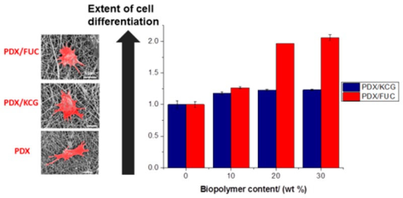
Furthermore, the cellular features observed were analyzed to quantify the morphological differences (Figure 8, Table 5). An increase in cell spread area has been correlated with osteogenic differentiation46−48 and an increase in nucleus size was concluded to translate into enhanced nuclear functional activity occurring during cell differentiation.49 The mean area of SaOS-2 cells cultured in osteogenic medium on the electrospun fibers was found to be almost twice that of cells cultured in normal proliferation conditions. Furthermore, cells grown in the normal proliferation medium were larger on the electrospun blend fibers compared to the PDX fibers. The same trend was noted for cells grown under osteogenic differentiation conditions, i.e., these cells were larger in size on the blend fibers compared to PDX. This implies that the addition of polysaccharides improved the innate osteogenic differentiation capacity of the fibers. In addition, as expected, cells grown in osteogenic differentiation medium differentiated more in comparison to those cultured in proliferation medium.
Figure 8.

Fluorescence microscopy images of SaOS-2 cell seeded on (A) PDX, (B) 70/30 PDX/KCG, and (C) 70/30 PDX/FUC mats in proliferation medium; (D) PDX and (E) 70/30 PDX/KCG and (C) 70/30 PDX/FUC mats in osteogenic differentiation medium. The actin filaments are stained in red using Rhodamin-Phalloidin and the cell nuclei are stained in blue using Hoechst.
Table 5. Summary of Cell Features in Both Proliferation and Differentiation Medium.
| cell features | PDX | PDX/KCG 70/30 | PDX/FUC 70/30 |
|---|---|---|---|
| proliferation medium | |||
| cell area (× 103 μm2) | 7.3 ± 1.1 | 16.4 ± 2.0 | 11.7 ± 1.9 |
| nucleus area (μm2 (×103) | 1.7 ± 0.4 | 2.5 ± 0.8 | 2.0 ± 0.4 |
| osteogenic differentiation medium | |||
| cell area (×103 μm2) | 18.3 ± 2.4 | 34.5 ± 9.9 | 21.4 ± 8.7 |
| nucleus area (× 103 μm2) | 2.0 ± 0.5 | 3.4 ± 0.9 | 2.4 ± 0.6 |
Alizarin Red Staining
During the process of osteogenic differentiation by SaOS-2 cells, calcium salts are formed. These can be used as an indirect osteogenic differentiation marker. In this study, an Alizarin red staining was used to quantify the calcium ions formed during the differentiation process. Alizarin Red stain binds selectively to the calcium deposits, resulting in the formation of red color, which can be quantified by UV/vis spectroscopy. In Figure 9 it can be noted that the addition of the biopolymers led to an increase in the relative absorbance values, which was significantly higher for PDX/FUC fibers compared to PDX/KCG fibers (compare also Figure S5).
Figure 9.

Relative absorbance values of Alizarin-Red S staining on PDX/KCG and PDX/FUC on (A) day 7 and (B) day 14 in differentiation experiments with SaOS-2 cells. The absorbance of PDX was set to 1 and the absorbance values of the corresponding blends were expressed relative to that of PDX. Statistical analysis was conducted using a two-way ANOVA. Data from days 7 and 14 were analyzed separately. Blend composition and blend systems were considered as the two varying factors. * p < 0.05, ** p < 0.0001, and (ns) not significant.
In summary, the incorporation of the anionic polysaccharides KCG or FUC in electrospun blend fibers with PDX led to a significantly improved NIH3T3 and SaOS-2 cell viability compared to pure PDX fibers. In addition, the innate osteogenic differentiation capacity of the blend fibers was higher than that of the pure PDX scaffold material. Among the biopolymer studied, FUC led to better osteogenesis compared to KCG. Comparing fibers with similar PDX/KCG blend composition with the corresponding PHB/KCG and PHBV/KCG studied before,18 it can be noted that the PDX/KCG scaffold material acted as a better substrate for NIH3T3 cell proliferation. Indeed, according to the MTT assays, NIH3T3 cells grown on PDX/KCG fibers proliferated more than those cultured on PHB/KCG or PHBV/KCG fibers (Figure S6). However, compared to PDX/KCG and PHB/KCG fibers, PHBV/KCG fibers enhanced the formation of Ca minerals via improved differentiation of SaOS-2 cells (Figure S7). The performances of PHB/KCG and PDX/KCG in terms of SaOS-2 differentiation were almost similar.
Cell Viability of Induced Pluripotent Stem Cell Colonies and Embryoid Bodies
The improvement observed with the blend fibers motivated a first set of experiments with human induced pluripotent stem cells (iPS cells), which have been shown to be promising for TE applications. Recently, several studies have been conducted, in which the viability, proliferation and differentiation of iPS cells were assessed on electrospun fibers.50,51 As evidenced by live/dead staining, electrospun polycaprolactone scaffolds supported the growth of human iPS cells.50 Furthermore, these cells could differentiate into neuronal cells. Electrospun polystyrene scaffolds were shown to be suitable for the long-term expansion and differentiation of human iPSCs.51 Following the significant improvements noted in terms of cell response on the electrospun PDX/KCG mats compared to PHB/KCG or PHBV/KCG blend mats, we evaluated the suitability of electrospun PDX/KCG blend mats for iPS cell culture. The iPS cells were cultured on Matrigel coated TCPS plates and later the iPS colonies were detached, counted and used for embryoid body (EB) formation using the hanging drop method. After 24 h incubation at 37 °C, the EBs were flushed using culture medium (Figure S8) and then seeded on fibronectin precoated electrospun mats. The electrospun mats were coated with fibronectin prior to EB seeding as EBs were found not to attach to the mats and to float in the cell medium, when fibronectin was not used. SEM images of the EBs after 3 days in culture on the electrospun mats are shown in Figure 10. As indicated by the red dotted lines in Figure 10, the iPS cells from the EBs start to attach and proliferate on the surface of the electrospun mat. The viability of the EBs on the electrospun substrates was also investigated via the live–dead staining method (Figure 11). The iPS cells maintained high viability as noted from the small number of dead cells stained in red. Moreover, the EBs grew and expanded considerably in size after 7 days. Thus, the preliminary data acquired with iPS cells in this study suggest that the PDX/KCG and PDX/FUC electrospun blend mats possess the potential to be used in combination with iPS cells for TE applications. Further studies are ongoing to evaluate the osteogenic differentiation potential of human iPS cells on these electrospun blend fibers.
Figure 10.

SEM images of EBs seeded on electrospun PDX/KCG mats after 3 days culture.
Figure 11.

Fluorescence images of EBs stained after 2 days culture on (A) PDX, (B) PDX/KCG 70/30, and (C) PDX/FUC 70/30 and after 7 days on (D) PDX, (E) PDX/KCG 70/30, and (F) PDX/FUC 70/30.
Conclusions
In this study, the potential of electrospun PDX/KCG and PDX/FUC blend fibers as cell culture substrates for tissue engineering applications was investigated using NIH3T3, SaOS-2 and human induced pluripotent stem cells. ATR-FTIR, DSC and TGA data suggested the presence of hydrogen bonds in PDX/KCG blends in contrast to PDX/FUC. The immiscibility in PDX/FUC blends led to higher extent of hydrolytic degradation as evidenced by more regions of fiber melting compared to PDX and PDX/KCG fibers. The NIH3T3 and SaOS-2 cell viability assays confirmed that the addition of KCG and FUC resulted in a lower number of dead cells and therefore improved cell response. According to the MTT assay, the PDX/KCG blend fibers showed the highest NIH3T3 cell proliferation after 7 days. Furthermore, SaOS-2 cells showed substantial changes in their morphology, when cultured on PDX, PDX/KCG and PDX/FUC fiber mats. These changes in cell morphology indicated osteogenic differentiation, which was further confirmed by Alizarin red staining of the Ca deposits formed. PDX/FUC blend fibers were shown to promote the differentiation of SaOS-2 cells to a larger extent compared to PDX/KCG in the absence of external biological cues. In addition, the fabricated electrospun mats supported the culture of EBs produced from human iPS cells. SEM images and live–dead staining showed that the EBs attached and proliferated after 3 days and that the iPS cells maintained high cell viability after 7 days, respectively. These results clearly underline the potential of biopolymers, in particular KCG and FUC, blended with other degradable polymers in electrospun blend fiber mats for use as cell culture substrates for TE.
Acknowledgments
We thank Dr. Yvonne Voß, Dipl.-Ing. Gregor Schulte, and Dipl.-Chem. Ing. Petra Frank for their support and helpful advice, as well as Dr. Ulrike Ritz (University Medical Center of the Johannes Gutenberg University Mainz, Germany) and Dr. Jürgen Schnekenburger (Biomedical Technology Center of the Medical Faculty Münster, Germany), who kindly provided the cell lines. We are also very grateful to Dr. Artjom Herberg and Prof. Dr. Dirk Kuckling (Universität Paderborn, Germany) for the GPC analysis of PDX.
Glossary
Abbreviations
- ATR-FTIR
attenuated total reflectance-Fourier transform infrared spectroscopy
- BTE
bone tissue engineering
- CHCl3
chloroform
- DSC
differential scanning calorimetry
- DMEM
Dulbecco’s modified Eagle’s media
- DMF
dimethylformamide
- EB
embryoid bodies
- ECM
extracellular matrix
- FUC
fucoidan
- GAG
glycosaminoglycans
- HFIP
1,1,1,3,3,3-hexafluuoroisopropanol
- iPS
induced pluripotent stem cells
- KCG
kappa-carrageenan
- PBS
phosphate buffer solution
- PDX
polydioxanone
- SEM
scanning electron microscopy
- TGA
thermogravimetric analysis
- TE
tissue engineering
Supporting Information Available
The Supporting Information is available free of charge on the ACS Publications website at DOI: 10.1021/acsbiomaterials.7b00350.
(DSC curves of PDX/KCG and PDX/FUC blend fibers; TGA curves of PDX/KCG and PDX/FUC blend fibers; graph depicting the fraction of live v/s dead NIH3T3 and SaOS-2 cells on PDX, PDX/KCG 70/30, and PDX/FUC 70/30 scaffolds after 24 h; MTT assay results obtained in experiments of NIH3T3 cells on PDX/KCG and PDX/FUC fibers on days 3 and 7; absorbance of Alizarin-Red S staining of PDX/KCG and PDX/FUC after 14 days in differentiation experiments of SaOS-2 cells; MTT assay results obtained in experiments of NIH3T3 cells on PHB/KCG and PHBV/FUC fibers on day 7; relative absorbance values of Alizarin-Red S staining of PHB/KCG and PHBV/KCG on day 14 in differentiation experiments of SaOS-2 cells; optical microscopy images of flushed EBs at low magnification and single EB at higher magnification (PDF)
The authors acknowledge generous financial support from the Alexander von Humboldt Foundation (Georg Forster postdoc stipend to N.G.), the European Research Council (ERC project ASMIDIAS, Grant 279202) and the University of Siegen.
The authors declare no competing financial interest.
Supplementary Material
References
- Jang J. H.; Castano O.; Kim H. W. Electrospun Materials as Potential Platforms for Bone Tissue Engineering. Adv. Drug Delivery Rev. 2009, 61, 1065–1083. 10.1016/j.addr.2009.07.008. [DOI] [PubMed] [Google Scholar]
- Henkel J.; Woodruff M. A.; Epari D. R.; Steck R.; Glatt V.; Dickinson I. C.; Choong P. F. M.; Schuetz M. A.; Hutmacher D. W. Bone Regeneration Based on Tissue Engineering Conceptions — A 21st Century Perspective. Bone Res. 2013, 1, 216–248. 10.4248/BR201303002. [DOI] [PMC free article] [PubMed] [Google Scholar]
- Burg K. G.; Porter S.; Kellam J. F. Biomaterial Developments for Bone Tissue Engineering. Biomaterials 2000, 21, 2347–2359. 10.1016/S0142-9612(00)00102-2. [DOI] [PubMed] [Google Scholar]
- Chiarello E.; Cadossi M.; Tedesco G.; Capra P.; Calamelli C.; Shehu A.; Giannini S. Autograft, Allograft and Bone Substitutes in Reconstructive Orthopedic Surgery. Aging Clin Exp Res. 2013, 25, S101–S103. 10.1007/s40520-013-0088-8. [DOI] [PubMed] [Google Scholar]
- Amini A. R.; Laurencin C. T.; Nukavarapu S. P. Bone Tissue Engineering: Recent Advances and Challenges. Crit Rev. Biomed Eng. 2012, 40, 363–408. 10.1615/CritRevBiomedEng.v40.i5.10. [DOI] [PMC free article] [PubMed] [Google Scholar]
- Kennedy K. M.; Bhaw-Luximon A.; Jhurry D. Cell-Matrix Mechanical Interaction in Electrospun Polymeric Scaffolds for Tissue Engineering: Implications for Scaffold Design and Performance. Acta Biomater. 2017, 50, 41–55. 10.1016/j.actbio.2016.12.034. [DOI] [PubMed] [Google Scholar]
- Meng X.; Leslie P.; Zhang Y.; Dong J. Stem Cells in a Three-Dimensional Scaffold Environment. SpringerPlus 2014, 3, 80–88. 10.1186/2193-1801-3-80. [DOI] [PMC free article] [PubMed] [Google Scholar]
- Burdick J. A.; Vunjak-Novakovic G. Engineered Microenvironments for Controlled Stem Cell Differentiation. Tissue Eng., Part A 2008, 15, 205–219. 10.1089/ten.tea.2008.0131. [DOI] [PMC free article] [PubMed] [Google Scholar]
- Dawson E.; Mapili G.; Erickson K.; Taqvi S.; Roy K. Biomaterials for stem cell differentiation. Adv. Drug Delivery Rev. 2008, 60, 215–228. 10.1016/j.addr.2007.08.037. [DOI] [PubMed] [Google Scholar]
- Lannutti J.; Reneker D.; Ma T.; Tomasko D.; Farson D. Electrospinning for Tissue Engineering Scaffolds. Mater. Sci. Eng., C 2007, 27, 504–509. 10.1016/j.msec.2006.05.019. [DOI] [Google Scholar]
- Agarwal S.; Wendorff J. H.; Greiner A. Progress in the Field of Electrospinning for Tissue Engineering Applications. Adv. Mater. 2009, 21, 3343–3351. 10.1002/adma.200803092. [DOI] [PubMed] [Google Scholar]
- Pham Q. P.; Sharma U.; Mikos A. G. Electrospinning of Polymeric Nanofibers for Tissue Engineering Applications: A Review. Tissue Eng. 2006, 12, 1197–1211. 10.1089/ten.2006.12.1197. [DOI] [PubMed] [Google Scholar]
- Rim N. G.; Shin C. S.; Shin H. Current approaches to electrospun nanofibers for tissue engineering. Biomed. Mater. 2013, 8, 014102. 10.1088/1748-6041/8/1/014102. [DOI] [PubMed] [Google Scholar]
- Zhang S.; Prabhakaran M. P.; Qin X.; Ramakrishna S. Biocomposite Scaffolds for Bone Regeneration: Role of Chitosan and Hydroxyapatite within Poly-3-hydroxybutyrate-co-3-hydroxyvalerate on Mechanical Properties and In Vitro Evaluation. J. Mech Behav Biomed Mater. 2015, 51, 88–98. 10.1016/j.jmbbm.2015.06.032. [DOI] [PubMed] [Google Scholar]
- Ramier J.; Bouderlique T.; Stoilova O.; Manolova N.; Rashkov I.; Langlois V.; Renard E.; Albanese P.; Grande D. J. Mater. Sci.: Mater. Med. 2014, 25, 1563–1575. 10.1007/s10856-014-5174-8. [DOI] [PubMed] [Google Scholar]
- Silva S. S.; Fernandes E. M.; Pina S.; Silva-Correia J.; Vieira S.; Oliveira J. M.; Reis R. L. In Comprehensive Biomaterials II, 2nd ed.; Ducheyne P., Healy K. E., Hutmacher D. E., Grainger D. W., Kirkpatrick C. J., Eds.; Elsevier: Amsterdam, 2017; p 187. [Google Scholar]
- Goonoo N.; Bhaw-Luximon A.; Passanha P.; Esteves S. R.; Schönherr H.; Jhurry D. Biomineralization Potential and Cellular Response of PHB and PHBV Blends with Natural Anionic Polysaccharides. Mater. Sci. Eng., C 2017, 76, 13–24. 10.1016/j.msec.2017.02.156. [DOI] [PubMed] [Google Scholar]
- Goonoo N.; Khanbabaee B.; Steuber M.; Bhaw-Luximon A.; Jonas U.; Pietsch U.; Jhurry D.; Schönherr H. κ–Carrageenan Enhances the Biomineralization and Osteogenic Differentiation of Electrospun PHB and PHBV Fibers. Biomacromolecules 2017, 18, 1563–1573. 10.1021/acs.biomac.7b00150. [DOI] [PubMed] [Google Scholar]
- Cirillo V.; Guarino V.; Ambrosio L. Design of Bioactive Electrospun Scaffolds for Bone Tissue Engineering. J. Appl. Biomater. Funct. Mater. 2012, 10, 223–228. 10.5301/JABFM.2012.10343. [DOI] [PubMed] [Google Scholar]
- Li W. J.; Laurencin C. T.; Caterson E. J.; Tuan R. S.; Ko F. K. Electrospun Nanofibrous Structure: A Novel Scaffold for Tissue Engineering. J. Biomed. Mater. Res. 2002, 60, 613–621. 10.1002/jbm.10167. [DOI] [PubMed] [Google Scholar]
- Feng W.; Feng S.; Tang K.; He X.; Jing A.; Liang G. A Novel Composite of Collagen-Hydroxyapatite/Kappa-carrageenan. J. Alloys Compd. 2017, 693, 482–489. 10.1016/j.jallcom.2016.09.234. [DOI] [Google Scholar]
- Tae Young A.; Kang J. H.; Kang D. J.; Venkatesan J.; Chang H. K.; Bhatnagar I.; Chang K. Y.; Hwang J. H.; Salameh Z.; Kim S. K.; Kim H. T.; Kim D. G. Interaction of Stem Cells with Nano Hydroxyapatite-Fucoidan Bionanocomposites for Bone Tissue Regeneration. Int. J. Biol. Macromol. 2016, 93, 1488–1491. 10.1016/j.ijbiomac.2016.07.027. [DOI] [PubMed] [Google Scholar]
- Luyt C. E.; Meddahi-Pellé A.; Ho-Tin-Noe B.; Colliec-Jouault S.; Guezennec J.; Louedec L.; Prats H.; Jacob M.; Osborne-Pellegrin M.; Letourneur D.; Michel J. P. Low-Molecular-Weight Fucoidan Promotes Therapeutic Revascularization in a Rat Model of Critical Hindlimb Ischemia. J. Pharmacol. Exp. Ther. 2003, 305, 24–30. 10.1124/jpet.102.046144. [DOI] [PubMed] [Google Scholar]
- Nakamura S.; Nambu M.; Ishizuka T.; Hattori H.; Kanatani Y.; Takase B.; Kishimoto S.; Amano Y.; Aoki H.; Kiyosawa T.; Ishihara M.; Maehara T. Effect of Controlled Release of Fibroblast Growth Factor-2 from Chitosan/Fucoidan Micro Complex-Hydrogel on In Vitro and In Vivo Vascularization. J. Biomed. Mater. Res., Part A 2008, 85, 619–627. 10.1002/jbm.a.31563. [DOI] [PubMed] [Google Scholar]
- Ray J. A.; Doddi N.; Regula D.; Williams J. A.; Melveger A. Polydioxanone (PDS), a novel monofilament synthetic absorbable suture. Surg. Gynecol. Obstet. 1981, 153, 497–507. [PubMed] [Google Scholar]
- Kalangos A. Polydioxanone Polymers for Annuloplasty in Heart Valve Repair. Macromol. Symp. 2005, 231, 81–83. 10.1002/masy.200590027. [DOI] [Google Scholar]
- Kalangos A.; Sierra J.; Vala D.; Cikirikcioglu M.; Walpoth B.; Orrit X.; Pomar J.; Mestres C.; Albanese S.; Jhurry D. Annuloplasty for Valve Repair with a New Biodegradable Ring: An Experimental Study. J. Heart Valve Dis. 2006, 15, 783–790. [PubMed] [Google Scholar]
- Goonoo N.; Jeetah R.; Bhaw-Luximon A.; Jhurry D. Polydioxanone-based Bio-Materials for Tissue Engineering and Drug/Gene Delivery Applications. Eur. J. Pharm. Biopharm. 2015, 97, 371–391. 10.1016/j.ejpb.2015.05.024. [DOI] [PubMed] [Google Scholar]
- Chen Z.; Song Y.; Zhang J.; Liu W.; Cui J.; Li H.; Chen F. Laminated Electrospun nHA/PHB-composite Scaffolds Mimicking Bone Extracellular Matrix for Bone Tissue Engineering. Mater. Sci. Eng., C 2017, 72, 341–351. 10.1016/j.msec.2016.11.070. [DOI] [PubMed] [Google Scholar]
- Boland E. D.; Coleman B. D.; Barnes C. P.; Simpson D. G.; Wnek G. E.; Bowlin G. L. Electrospinning Polydioxanone for Biomedical Applications. Acta Biomater. 2005, 1, 115–123. 10.1016/j.actbio.2004.09.003. [DOI] [PubMed] [Google Scholar]
- Madurantakam P. A.; Rodriguez I. A.; Cost C. P.; Viswanathan R.; Simpson D. G.; Beckman M. J.; Moon P. C.; Bowlin G. L. Multiple factor interactions in biomimetic mineralization of electrospun scaffolds. Biomaterials 2009, 30, 5456–5464. 10.1016/j.biomaterials.2009.06.043. [DOI] [PubMed] [Google Scholar]
- Rodriguez I. A.; Madurantakam P. A.; McCool J. M.; Sell S. A.; Yang H.; Moon P. C.; Bowlin G. L. Mineralization potential of electrospun PDOhydroxyapatite-fibrinogen blended scaffolds. Int. J. Biomater. 2012, 12, 1. 10.1155/2012/159484. [DOI] [PMC free article] [PubMed] [Google Scholar]
- Kim T. H.; Oh S. H.; Chun S. Y.; Lee J. H. Bone morphogenetic proteins immobilized polydioxanone porous particles as an artificial bone graft. J. Biomed. Mater. Res., Part A 2014, 102, 1264–1274. 10.1002/jbm.a.34803. [DOI] [PubMed] [Google Scholar]
- Lee J. H.; Kim J. H.; Oh S. J.; Kim S. J.; Hah Y. S.; Park B. W.; et al. Tissue engineered bone formation using periosteal-derived cells and polydioxanone/pluronic F127 scaffold with pre-seeded adipose tissuederived CD146 positive endothelial-like cells. Biomaterials 2011, 32, 5033–5045. 10.1016/j.biomaterials.2011.03.081. [DOI] [PubMed] [Google Scholar]
- Volery P.; Besson R.; Schaffer-Lequart C. Characterization of Commercial Carrageenans by Fourier Transform Infrared Spectroscopy Using Single-Reflection Attenuated Total Reflection. J. Agric. Food Chem. 2004, 52, 7457–7463. 10.1021/jf040229o. [DOI] [PubMed] [Google Scholar]
- Jhurry D.; Bhaw-Luximon A.; Mardamootoo T.; Ramanjooloo A. Biopolymers from the Mauritian Marine Environment. Macromol. Symp. 2005, 231 (1), 16–27. 10.1002/masy.200590020. [DOI] [Google Scholar]
- Rodriguez-Jasso R. M.; Mussatto S. I.; Pastrana L.; Aguilar C. N.; Teixeira J. A. Microwave-Assisted Extraction of Sulfated Polysaccharides (fucoidan) from Brown Seaweed. Carbohydr. Polym. 2011, 86, 1137–1144. 10.1016/j.carbpol.2011.06.006. [DOI] [Google Scholar]
- Hernandez-Montero N.; Meaurio E.; Elmiloudi K.; Sarasua J. R. Novel Miscible Blends of Poly(p-dioxanone) with Poly(vinyl phenol). Eur. Polym. J. 2012, 48, 1455–1465. 10.1016/j.eurpolymj.2012.05.009. [DOI] [Google Scholar]
- Moskala E. J.; Howe S. E.; Painter P. C.; Coleman M. M. On the Role of Intermolecular Hydrogen Bonding in Miscible Polymer Blends. Macromolecules 1984, 17, 1671–1678. 10.1021/ma00139a006. [DOI] [Google Scholar]
- Painter P. C.; Park Y.; Coleman M. M. Thermodynamics of Hydrogen Bonding in Polymer Blends. 2. Phase Behavior. Macromolecules 1989, 22, 580–585. 10.1021/ma00192a012. [DOI] [Google Scholar]
- McBeath R.; Pirone D. M.; Nelson C. M.; Bhadriraju K.; Chen C. S. Cell Shape, Cytoskeletal Tension, and RhoA Regulate Stem Cell Lineage Commitment. Dev. Cell 2004, 6, 483–495. 10.1016/S1534-5807(04)00075-9. [DOI] [PubMed] [Google Scholar]
- Yourek G.; Hussain M. A.; Mao J. J. Cytoskeletal Changes of Mesenchymal Stem Cells during Differentiation. ASAIO J. 2007, 53, 219–228. 10.1097/MAT.0b013e31802deb2d. [DOI] [PMC free article] [PubMed] [Google Scholar]
- Pablo Rodriguez J.; Gonzalez M.; Rios S.; Cambiazo V. Cytoskeletal Organization of Human Mesenchymal Stem Cells (MSC) Changes During Their Osteogenic Differentiation. J. Cell. Biochem. 2004, 93, 721–731. 10.1002/jcb.20234. [DOI] [PubMed] [Google Scholar]
- Matsuoka F.; Takeuchi I.; Agata H.; Kagami H.; Shiono H.; Kiyota Y.; Honda H.; Kato R. Characterization of Time-Course Morphological Features for Efficient Prediction of Osteogenic Potential in Human Mesenchymal Stem Cells. Biotechnol. Bioeng. 2014, 111, 1430–1439. 10.1002/bit.25189. [DOI] [PMC free article] [PubMed] [Google Scholar]
- Matsuoka F.; Takeuchi I.; Agata H.; Kagami H.; Shiono H.; Kiyota Y.; Honda H.; Kato R. Morphology-based Prediction of Osteogenic Differentiation Potential of Human Mesenchymal Stem Cells. PLoS One 2013, 8, e55082. 10.1371/journal.pone.0055082. [DOI] [PMC free article] [PubMed] [Google Scholar]
- Song W.; Kawazoe N.; Chen G. Dependence of Spreading and Differentiation of Mesenchymal Stem cells on Micropatterned Surface Area. J. Nanomater. 2011, 2011, 265251. 10.1155/2011/265251. [DOI] [Google Scholar]
- Mullen C. A.; Vaughan T. J.; Billiar K. L.; McNamara L. M. The Effect of Substrate Stiffness, Thickness, and Cross-Linking Density on Osteogenic Cell Behavior. Biophys. J. 2015, 108, 1604–1612. 10.1016/j.bpj.2015.02.022. [DOI] [PMC free article] [PubMed] [Google Scholar]
- Jhala D.; Rather H.; Vasita R. Polycaprolactone–Chitosan Nanofibers Influence Cell Morphology to Induce Early Osteogenic Differentiation. Biomater. Sci. 2016, 4, 1584–1595. 10.1039/C6BM00492J. [DOI] [PubMed] [Google Scholar]
- Tutak W.; Jyotsnendu G.; Bajcsy P.; Simon C. G. Jr Nanofiber Scaffolds Influence Organelle Structure and Function in Bone Marrow Stromal Cells. J. Biomed. Mater. Res., Part B 2017, 105, 989. 10.1002/jbm.b.33624. [DOI] [PMC free article] [PubMed] [Google Scholar]
- Mohtaram N. K.; Ko J.; King C.; Sun L.; Muller N.; Byung-Guk Jun M.; Willerth S. M. Electrospun Biomaterial Scaffolds with Varied Topographies for Neuronal Differentiation of Human-Induced Pluripotent Stem Cells. J. Biomed. Mater. Res., Part A 2015, 103, 2591–2601. 10.1002/jbm.a.35392. [DOI] [PubMed] [Google Scholar]
- Leong M. F.; Lu H. F.; Lim T. C.; Du C.; Ma N. K. L.; Wan A. C. A. Electrospun Polystyrene Scaffolds as a Synthetic Substrate for Xeno-free Expansion and Differentiation of Human Induced Pluripotent Stem Cells. Acta Biomater. 2016, 46, 266–277. 10.1016/j.actbio.2016.09.032. [DOI] [PubMed] [Google Scholar]
Associated Data
This section collects any data citations, data availability statements, or supplementary materials included in this article.