Abstract
Purpose
To investigate the effect of the asymmetric gradient concomitant fields (CF) with zeroth and first-order spatial dependence on fast/turbo spin-echo acquisitions, and to demonstrate the effectiveness of their real-time compensation.
Methods
After briefly reviewing the CF produced by asymmetric gradients, the effects of the additional zeroth and first-order CFs on these systems are investigated using extended-phase graph simulations. Phantom and in vivo experiments are performed to corroborate the simulation. Experiments are performed before and after the real-time compensations using frequency tracking and gradient pre-emphasis to demonstrate their effectiveness in correcting the additional CFs. The interaction between the CFs and prescan-based correction to compensate for eddy currents is also investigated.
Results
It is demonstrated that, unlike the second-order CFs on conventional gradients, the additional zeroth/first-order CFs on asymmetric gradients cause substantial signal loss and dark banding in fast spin-echo acquisitions within a typical brain-scan field of view. They can confound the prescan correction for eddy currents and degrade image quality. Performing real-time compensation successfully eliminates the artifacts.
Conclusions
We demonstrate that the zeroth/first-order CFs specific to asymmetric gradients can cause substantial artifacts, including signal loss and dark bands for brain imaging. These effects can be corrected using real-time compensation.
Keywords: fast spin echo, FSE, turbo spin echo, TSE, asymmetric gradient, concomitant field, extended phase graph, EPG
INTRODUCTION
Fast spin echo (FSE) or turbo spin echo (TSE) MR acquisitions are used widely for various clinical applications and are currently the workhorse for routine anatomical imaging (1–5). They assume that the Carr- Purcell-Meiboom-Gill (CPMG) condition is satisfied, which requires consistent phase accumulation between consecutive radiofrequency (RF) pulses. This ensures that the primary and stimulated echoes from different pathways contribute coherently to measured MR signals (1,6,7). However, the CPMG-based FSE acquisitions can be prone to various magnetic field perturbations (e.g., gradient eddy currents), which can cause inconsistent phase errors among different echo components and introduce artifacts including signal loss and ghosting (7).
The concomitant field (CF) is a source of phase error in FSE acquisitions that originates from the fundamental physical principles (i.e., the Maxwell’s equations (8)), which state that the divergence and curl of the magnetic field is zero in free space. Consequently, the linear-varying spatial-encoding gradient fields must always be accompanied by a series of undesired magnetic fields, termed Maxwell fields or CFs. They are present whenever a gradient is active, and cause accumulation of phase errors. The CF effect on whole-body MR gradient systems has been described previously. It causes artifacts including ghosting and distortion in echoplanar imaging (EPI) (9,10), blurring in spiral (11), and flow-quantification errors in phase-contrast acquisition (8).
Conventional, whole-body MR gradients typically use a symmetric design, with the coil current paths (generating gradient fields) on the service side mirroring that on the patient side (i.e., the gradient isocenter corresponds to the coil geometrical center). The CFs on such systems contain only terms of second-order spatial dependence or higher, and usually only the second-order terms are not negligible (8), especially at 1.5T and higher. The CF effect in FSE on whole-body MR systems has been investigated, and was shown to cause ghosting in large field-of-view (FOV) applications such as spine imaging (12), as the magnitude of the CF scales as the square of the distance from isocenter. Their effects, however, are usually negligible (at 1.5 T and higher) with image FOVs used for typical brain scans (18–24 cm) and the maximum gradient amplitudes (50 and 200 T/m/s) available on most whole-body gradients (12).
An alternative to the symmetric design is the asymmetric gradient system, in which the gradient isocenter is shifted away from the center of the coil, toward the patient-entry end (13–19). The asymmetric design is typically used for head-only or compact systems (18), in which this design gives patient (head) access to the imaging volume for a smaller-sized gradient coil. The smaller-sized gradient coil allows higher maximum gradient slew rate and amplitude as a result of reduced gradient coil inductance and resistance, as well as decreased peripheral nerve stimulation. In FSE and EPI acquisitions, the high gradient slew rate and amplitude can substantially shorten echo spacing, and improve imaging performance by increasing signal level and reducing susceptibility effects (20,21). However, the asymmetric design results in CFs that include additional terms of zeroth and first-order dependences, in addition to the usual second-order terms (16).
In this work, we investigate the effect of the zeroth and first-order CFs in FSE acquisitions on asymmetric gradients using the extend phase graphs (EPG) simulation (6,22,23), as well as phantom and in vivo experiments. As shown here, these additional CFs can cause prominent artifacts even within the FOV typically used for brain exams. We also demonstrate the effectiveness of the real-time compensation methods of frequency tracking (24) and gradient pre-emphasis (25), which counteract their effects.
THEORY
Effects of Asymmetric Gradient CFs in FSE
The effect of CFs in asymmetric gradient systems has been described previously in (16). The CFs accumulate spatial and temporal-dependent phase errors in transverse magnetization whenever the gradients are active. Denoting ϕi(x, t0) as the phase error induced by the CF to the magnetization forming the ith echo pathway up to a time point t0, the phase error caused by the CFs in a later time, t, can be expressed as (26)
| [1] |
For an FSE acquisition under CPMG condition, the readout and crusher gradients are typically symmetric around each refocusing pulse. Consequently, the previous phase accumulation resulting from these components before a refocusing pulse will be rewound and does not propagate throughout the echo train. Therefore, their effects are expected to be small (12). However, this is not the case for a phase-encoding gradient.
Consider a simplified case in which only the primary and the first stimulated echo contribute to the measured MR signals, with only the effects from phase-encoding gradient-induced CF taken into account. Assume the phase-encoding gradients (including the phase encoding and rewinder lobes) after the first refocusing pulse cause a total phase deviation of Φ(x). This phase error is only experienced by the magnetization forming the primary echo (ϕ1(x, t0) = Φ(x)), as they are in the transverse plane at that time, but not by the magnetization contributing to the simulated echo (ϕ2(x, t0) = 0), which are nutated back to the longitudinal axis. Following the second refocusing pulse, the previous phase accumulation is negated, and the primary echo forms at time TE, with ϕ1(x, TE) = −Φ(x) +Φ′(x)/2, where Φ′(x) ≠ Φ(x), as the phase-encoding gradient area typically varies among different readouts. The simulated echo pathway, however, experiences a dephasing for the amount of ϕ2(x, TE) = Φ′(x)/2. Hence, the signals from two pathways add up incoherently and lead to signal cancellation, the effect of which depends on Φ(x).
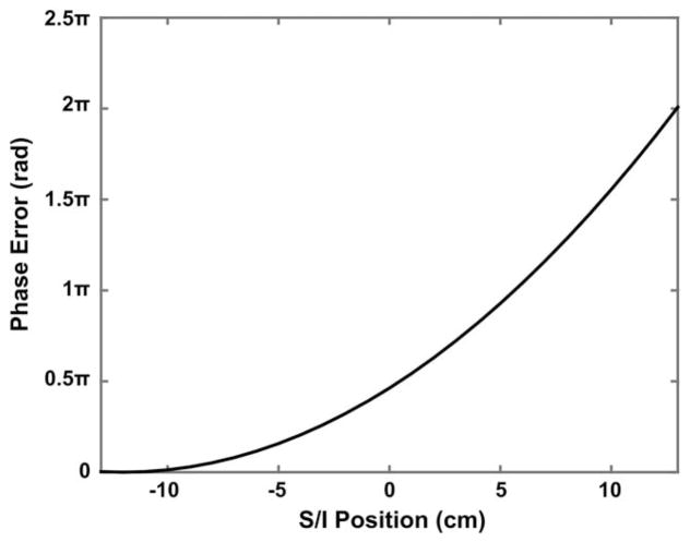
As an example, the CFs of the transverse asymmetric gradient coils that we use (18) for a 0.7-mm spatial resolution acquisition (sagittal acquisition, with readout in z) predict a Φ(x) ≈ 0.93π rad at 5 cm superior to isocenter, representing a substantial signal cancellation. The values of phase error Φ(x) at different locations along the superior/inferior (S/I) axis across the 26-cm diameter spherical volume of the gradient coil are also shown in Figure 1, which demonstrates that the phase error is spatially variant and is stronger at the superior end of the imaging volume. Moreover, for an acquisition using a longer echo train, the phase error from CFs can accumulate and propagate throughout the entire echo train, which can further aggregate this effect.
FIG. 1.
Phase error (Φ(x)) as a result of the CF from the phase-encoding gradient along the y-axis (Fig. 2a) and the corresponding rewinder gradient for a sagittal T2-weighted FSE acquisition at different locations along the S/I axis across the 26-cm diameter spherical volume of the gradient coil reported in (18).
Compensation of the Asymmetric Gradient CFs
The CF effects can be reduced by using a lower phase-encoding gradient amplitude (12). However, this strategy increases echo spacing and minimum echo time (TE), which can reduce signal level and increase acquisition time. Alternatively, the first-order CFs on asymmetric gradients can be compensated using a real-time gradient pre-emphasis technique that prospectively accounts for their effects for any arbitrary gradient waveform, so that the acquired MR signal is free from their interference, as we demonstrated previously (25). Denoting the ideal gradient waveforms as Gx(t), Gy(t), and Gz(t), the first-order CFs can be eliminated by identifying the actual gradient fields , and according to the following pre-emphasis scheme:
| [2a] |
| [2b] |
| [2c] |
where the dimensionless parameter α describes the relative CF strength from z-gradient along the x- versus y-axis; z0x and z0y are asymmetric gradient parameters describing the offsets of x- and y-gradients from isocenter along the z-axis; x0 and y0 denote the z-gradient coil offset along the x- and y-axes. Similarly, the zero-order terms can be compensated in real time by shifting the RF transmit/receive frequency by the amount (Δf0th) predicted by CF based on the gradient waveforms
| [3] |
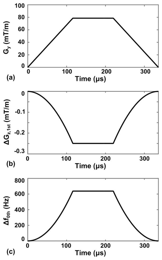
similar to the zeroth-order eddy current compensation on clinical MR scanners (27). Using these two methods, the effects from the additional zeroth and first-order CFs on asymmetric gradients can be entirely eliminated with no additional pulse sequence programing, leaving only the same second-order terms that are present on conventional, symmetric gradient systems. For the case shown in Figure 1, the z-gradient pre-emphasis component ( ) and frequency shift (Δf0th(t)) resulting from the first- and zeroth-order CFs are shown in Figure 2, with the maximum values for compensation gradient and frequency shift of 0.25 mT/m and 638 Hz, respectively.
FIG. 2.
a: Waveform of a phase-encoding gradient lobe along the y-gradient axis (Gy). b: First-order CF pre-emphasis component along the z-gradient axis (ΔGz,1st), designed for the gradient waveform in (a). c: Zeroth-order CF compensating frequency shift (Δf0th).
METHODS
Extend Phase Graph Simulation
The EPG simulations (1,22,23) were performed to investigate the CF effects, assuming the configuration of the asymmetric gradient in our institution (80 mT/m gradient amplitude and 700 T/m/s slew rate, simultaneously on all three axes). This research system (GE Global Research, Niskayuna, NY) uses asymmetric x- and y-gradients and a symmetric z-gradient, with geometrical parameters α = 0.5, x0 = y0 = 0, and z0x = z0y = 12 cm. The gradient has a 42-cm inside diameter, yielding a system with 26-cm diameter spherical volume capable of scanning heads, extremities, and infants (18). The gradient is integrated with a compact, extremely low helium volume 3T magnet (18,28). The system runs standard, version 25.0 GE software, with the addition of firmware patches to compensate for zeroth- and first-order CFs using frequency tracking and gradient pre-emphasis, respectively.
The EPG method is a powerful tool that has been used widely in the design and analysis of a variety of MR pulse sequences, such as the FSE and rapid gradient echo acquisitions (e.g., steady-state free precession) (1,6,22,23). Some classic examples of EPG use include the simulation of echo signal intensity for CPMG-based FSE acquisitions, and the effect of gradient and RF spoiling in gradient-echo acquisitions. Instead of analyzing the magnetization response using the physical x, y, and z coordinates (i.e., Mx, My, and Mz) based on rotation operators, the EPG uses the complex transverse magnetization vectors M+ = Mx + jMy and M− = Mx − jMy to represent the dephasing and rephasing transverse magnetization components, respectively. To simplify the analysis of gradient-induced dephasing, the EPG decomposes the transverse (M+ and M−) and longitudinal (Mz) magnetizations into groups of isochromats of different dephasing states using the Fourier relationship, which are known as configuration states. Under this framework, various components of a pulse sequence such as RF pulses, T1/T2 relaxations, and gradient activity–induced dephasing can be modularized as a series of matrix operations sequentially acting on the said configuration states according to the pulse sequence scheme of interest. The gradient-induced dephasing in transverse magnetization (e.g., as a result of crusher gradients before and after the refocusing pulses) can be modeled as a transition of different transverse configuration states. The effect of a RF pulse can be modeled as a linear superposition of the transverse and longitudinal states denoted by a linear transformation, and tissue T1/T2 relaxations can be taken into account as decay and recovery of configuration states, correspondingly.
For a CPMG-based FSE acquisition with equally spaced refocusing RF pulses and periodic gradient activities, the magnetizations within an image voxel can be decomposed using the following Fourier series representation:
| [4a] |
| [4b] |
| [4c] |
where F+(k), F−(k), and Z(k) are Fourier coefficients representing the kth configuration states of the transverse dephasing (M+ = Mx + jMy ), rephasing (M− = Mx − jMy ), and longitudinal (Mz) magnetization components, respectively. The dephasing and rephasing configuration states share conjugate symmetry (i.e., F−(k) = (F+(−k))*). denotes the gradient-induced dephasing within half of an echo spacing (ESP) time interval along the spatial axis (r) for an FSE sequence. The EPG framework typically assumes that all F+(k) and F−(k) with k ≠ 0 are fully dephased across the pixel (i.e., Δkr = 2π). Therefore, the echo signal can be calculated from the transverse configuration state F+(0) alone, which represents the fully rephased isochromats.
We denote F as a 3 × K matrix (K = 2 × ETL + 1) with the kth column representing the kth transverse and longitudinal configuration state vector as follows:
| [5] |
where the conjugate symmetry relation F−(k) = (F+(−k))* is used. Under the EPG framework, the gradient-induced dephasing within each ESP/2 time interval in an FSE acquisition can be modeled using an operator S{F}, which shifts the transverse configuration states (F+(k)) to higher states, while leaving the longitudinal states (Z(k)) intact: F+(k) → F+(k + 1), (i.e., F−(k) → F−(k − 1)), and Z(k) → Z(k)). Similarly, the effects of a RF pulse and tissue relaxation can be represented as a complex linear transformation matrix Ti,θ and a scaling operator Eτ,T1,T2{F} that operate on each of the kth configuration states, individually, where i and θ are the axes along which the RF pulse is applied (e.g., i=x, y, and z) and the flip angle (FA) of this pulse, respectively; and τ, T1, and T2 are the time intervals for relaxation and the characteristic relaxation-time constants of a specific tissue. (Please see the Appendix for detailed implementation using matrix expressions for each individual operator.) Under ideal conditions (without the CF effect), the configuration state matrix at the first echo center, F1, following a 90° excitation pulse along the y-axis, can be expressed as
| [6a] |
where F0 = δ3[2](δK [0])T is the initial configuration state with δR[r] denoting a R × 1 vector in which the rth element (0 ≤ r ≤ R − 1) is equal to “1” and otherwise zero-valued; Ty,90° denotes the 90° pulse that tips the longitudinal configuration states into transverse configuration states; EESP/2,T1,T2 {·} is the tissue relaxation process during the time interval of ESP/2, either between the excitation pulse and the first refocusing pulse, or between the echo center and nearby refocusing pulses; S{·} denotes the shift of transverse configuration states as a result of gradient dephasing in the ESP/2 time interval; Tx,α is the refocusing pulse applied along the x-axis with a FA, α. Similarly, the configuration state at the nth echo center can be expressed as
| [6b] |
For the reason discussed previously, the phase-encoding-gradient- induced CF can cause additional dephasing on the magnetization. Its effect can be included as an additional dephasing operator Φ acting on the configuration state matrix, which gives
| [7a] |
for the first echo, and
| [7b] |
for later echoes (n < ETL). Here, Φdephaser and Φrewinder represent the phase accumulation caused by the phase encoding and rewinder gradient lobes before and after readout, respectively. Similar to the operator Ti,θ, the Φdephaser and Φrewinder do not explicitly depend on k. It can be implemented by using a linear scaling matrix denoting the CF-induced dephasing to each of the kth configuration states as
| [8] |
where ϕBc is the CF-induced phase error evaluated based on Equations [2] through [6] in (25) as . Note that ϕBc has both spatial and temporal dependences, and therefore needs to be calculated based on different pixel spatial locations using phase encoding or rewinding gradient waveforms specific to each readout.
To simulate the effect of CF in FSE acquisitions on the asymmetric gradient, the EPG simulation was performed assuming the gradient waveforms of a 2D sagittal T2- weighted FSE acquisition (FOV=26×26cm2, number of phase encoding=384, readout direction=S/I, echo train length (ETL)=16, bandwidth (BW)=±62.5 kHz, ESP=7.0 ms, refocusing pulses FA=111°, TE=111.6 ms). The T1 and T2 values of normal white matter at 3T were assumed (T1/T2=1100/70 ms). For the reason described in the “Theory” section, only the CF effect from the phase-encoding gradient was simulated. A sagittal acquisition with phase-encoding gradient along the physical y-axis was chosen, as the CF artifacts are more prominent in this configuration. The CF effects were included by adding transverse dephasing based on Equations [7] and [8]. To separately observe the effect from CFs of different orders, a simulation was performed including all terms (zeroth, first, and second order), only the first/second-order terms, only the zeroth/second-order terms, and only the second-order terms, respectively. The signal strength at the center of each echo (F+(0) state) was recorded, and a total of 24 echo trains (ETL=16) were repeated to acquire the entire 384 phase-encoding lines for each case. The point spread function (PSF) in the phase-encoding direction was then calculated by applying a discrete Fourier transform to the measured signals.
Phantom Experiments
The American College of Radiology (ACR) MRI phantom was scanned on the asymmetric gradient system using a 2D sagittal T2-weighted FSE acquisition and the single-channel transmit/receive coil integrated with the gradient. The data acquisition parameters were chosen to match the simulation (FOV=26×26cm2, matrix=384×384, ETL=16, BW=±62.5 kHz, ESP=7.0 ms, refocusing pulse FA=111°, readout direction=S/I, TE=111.6 ms, repetition time (TR)=5000 ms, slice thickness=7 mm). Images were acquired with all four settings with the zeroth and first-order CF compensation (CFC) disabled, and then enabled, to separate their effects. The first and zeroth-order CFC firmware patches were implemented (based fully on Eqs. [2] and [3]) on the gradient digital-to-analog controller and RF frequency control systems, respectively, to provide prospective, real-time compensation (24,25), analogous to the conventional eddy current pre-emphasis and frequency shifting (7,27). After these real-time compensations, no further correction of zeroth and first-order CFs was required.
The scanner has a user-selectable artifact reduction technique (known as “FSE phase correction”). This technique estimates the phase errors arising from gradient activity (typically from zeroth and first-order eddy current) using a separate calibration prescan, and then compensates them by applying a RF phase shift and gradient area adjustment in the subsequent data acquisition (29). To observe any interaction between this FSE phase correction (PC) and the CFs, the ACR phantom was scanned (2D coronal acquisition, FOV=26×26cm2, matrix=384×384, ETL=16, BW=±62.5 kHz, ESP=7.2 ms, refocusing pulse FA=111°, readout direction=S/I, TE=111.6 ms, TR=5000 ms, slice thickness=4mm) before and after enabling the FSE PC, with and without the zeroth and first-order CFC, respectively.
The ACR phantom was further scanned in an eight-channel coil using a 2D axial FSE acquisition (FOV=22×22cm2, matrix=320×320, ETL=12, BW= ±31.25 kHz, ESP=8.0 ms, refocusing pulse FA=111°, readout direction=anterior/posterior, TE=96.4 ms, TR=4000 ms, slice thickness=5mm) and a 3D T2 CUBE FLAIR acquisition (GE Healthcare, Little Chalfont, United Kingdom) (FOV=25.6×25.6cm2, matrix=320×320, slice thickness =1mm, number of slices=200, ETL=200, BW=±62.5 kHz, ESP=3.5 ms, readout direction=S/I, TE=111 ms, TR=7600 ms) before and after enabling the CFC patches. Each scan was repeated twice using the identical setup with the raw data retained for offline processing. The k-space data acquired from two identical sequences were then separately reconstructed coil-by-coil using a type I nonuniform fast Fourier transform–based image reconstruction framework implemented with a 1.25× oversampled FFT operator and a five-point Kaiser-Bessel kernel (30,31). This reconstruction method prospectively corrects for gradient nonlinearity– induced image distortion while preventing the low-pass filtering effect on images (and noise) observed after the conventional image-domain interpolation-based correction. Each image pair was then subtracted from each other, coil-by-coil, to remove the background structure, and the sum-of-squares was combined to yield the noise image. The signal-to-noise ratio (SNR) values were then measured from the images before and after CFC as the ratio between the mean signal level in the sum-of-square combined anatomical image and the standard deviation of the noise image based on the selected regions of interest (ROIs).
In Vivo Experiments
Under an internal review board–approved protocol, the brain of a healthy volunteer was scanned in a standard eight-channel receive-only coil using a 2D sagittal T2- weighted FSE acquisition (FOV=22×22cm2, matrix=512×384, BW=±62.5 kHz, ETL=16, echo spacing=7.3 ms, refocusing pulse FA=111°, slice thickness =4mm, TR=5000 ms, TE=116 ms, readout direction=S/I). Separate scans were performed with (i) both CFCs disabled, (ii) only zeroth-order CFC enabled, (iii) both zeroth and first-order CFCs enabled, and (iv) both CFCs, as well as FSE PC enabled. The brain of another healthy volunteer was further scanned using a 2D oblique axial T2-weighted FSE acquisition (FOV=22×22cm2, matrix=320×320, number of excitations=2, slice thickness=4mm, BW=±31.25 kHz, TR=4969 ms, ETL=12, TE=98.6 ms, readout- =anterior/posterior, phase encoding=right/left, ASSET factor=2) with and without CFCs in a 32-channel receive-only brain coil. The FSE PC was enabled during these scans.
RESULTS
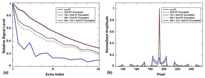
Figure 3a shows the relative echo signal strengths along the echo train in a single TR period at 5 cm away from gradient isocenter (along z-axis) obtained from the EPG simulation. The second-order CFs, which are present on both symmetric and asymmetric gradients, show very little impact on the echo signal (black solid line versus red dashed line). The zeroth and first-order CFs, which are only produced in the asymmetric gradients, can cause considerable signal loss and signal fluctuation along the echo train (purple, green, blue lines), even only 5 cm away from the isocenter. Figure 3b shows the PSFs along the phase-encoding direction of each case. Note the reduced amplitude of central peaks in the zeroth/first-order CF corrupted cases. Also note the increased side lobes in the PSFs as a result of signal fluctuation, which can cause ghosting in the reconstructed images.
FIG. 3.
a: Echo signal strength of different echoes along a 16-echo train in one TR, with and without the effect of CFs obtained from the EPG simulation (corresponding to a spatial position 5-cm shifted superiorly from gradient isocenter). b: Point sread function in the phase-encoding direction for different cases in (a), calculated from the EPG simulation.
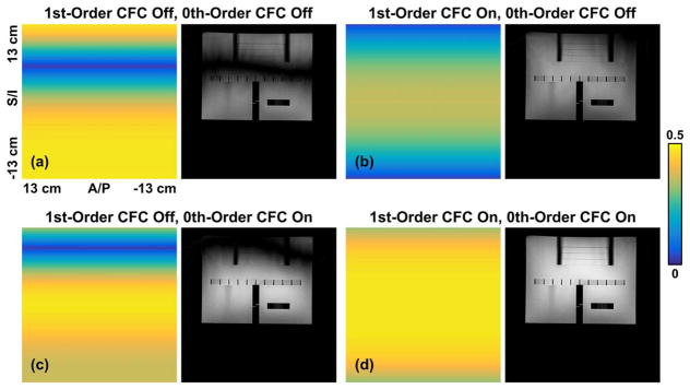
The pixel intensity maps across the 26-cm FOV in the sagittal T2 FSE scan are calculated from simulation as the amplitude of the central peak of PSF before and after zeroth and/or first-order CFC, and are shown in Figure 4 (left panels). The ACR phantom images acquired with matching acquisition parameters are shown (in the same window level) in the right panels. The second-order CFs have a relatively small effect (Fig. 4d) in this FOV. In contrast, the first-order CFs introduce a hypointense band in the reconstructed images (Figs. 4a and 4c), whereas the zeroth-order CFs cause a global signal loss. Note the reduced image intensity and more apparent noise in Figure 4b versus 4d. The zeroth and first-order CFs also introduce image ghosting (Figs. 4a–4c), which is inconsistent with Figure 3a. These artifacts are largely reduced after CFC (Fig. 4d).
FIG. 4.
Pixel intensity maps (left panels) across the 26-cm FOV obtained from the EPG simulation after zeroth and/or first-order CFC, and phantom images acquired using matching acquisition parameters (right): a: before zeroth and first-order CFC; b: with only first-order CFC; c: with only zeroth-order CFC; d: with both zeroth and first-order CFC.
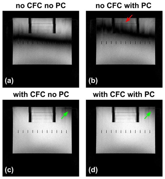
The phantom images acquired before and after FSE PC and zeroth/first-order CFC are shown in Figure 5, which demonstrate the interaction between them. Note that FSE PC performed without CFC (Figs. 5a and 5b) cannot eliminate the banding artifacts, but degrades the image quality and increases ghosting (red arrow). A comparison of Figures 5c and 5d shows that the signal dropout can be further reduced after applying PC if CFs are also compensated. The remaining ghosting close to the superior end of the phantom is suspected to be caused by residual eddy current effects.
FIG. 5.
Phantom images acquired before and after zeroth/first-order CFC and the product eddy current prescan-based compensation (FSE PC on the GE system), showing their interaction. Phase correction can degrade the image quality without the zeroth/first-order CFC ((a) versus (b)). The signal loss (green arrows) can be further reduced after PC if the CFC was also applied ((c) versus (d)). The ghosting close to the phantom superior end is suspected to be residual eddy current effects.
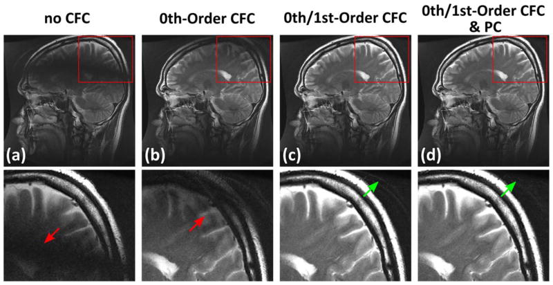
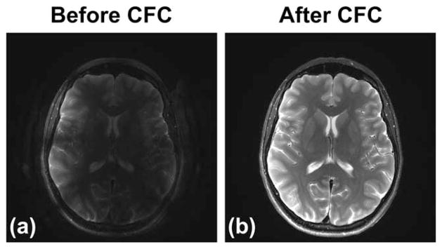
Examples of an in vivo brain scan using a sagittal T2 FSE acquisition before and after CFC and FSE PC are shown in Figure 6. Consistent with the phantom results, Figure 6 demonstrates the dark band caused by the first-order CFs (red arrows), which is eliminated after compensation. Further applying the PC onto images after CFC can reduce the ghosting toward the vertex (green arrows). Figure 7 shows an example from images acquired using an axial-oblique T2 FSE protocol before and after CFC. Note the decreased conspicuity of brain structures caused by signal loss and ghosting (Fig. 7a), which is improved after real-time CFC. Also note that the real-time gradient pre-emphasis and frequency shifting methods (Eqs. [2] and [3]) used here assume arbitrary gradient waveforms, and therefore can be used to fully compensate for the CF effects of an arbitrary acquisition plane, such as the axial-oblique plane in this example.
FIG. 6.
Examples of 2D sagittal T2 FSE images acquired on a healthy volunteer: a: image before CFC; b: with zeroth-order CFC; c: with zeroth and first-order CFC; d: with zeroth and first-order CFC as well as FSE PC. Note the black band caused by the first-order CF (red arrows). These effects are largely removed after CFC (c). The FSE PC applied after CFC can further suppress the ghosting (d) observed at the peripheral of FOV (green arrows).
FIG. 7.
Example of images acquired using a clinical oblique-axial T2 FSE acquisition before (a) and after (b) the zeroth/first-order CFC.
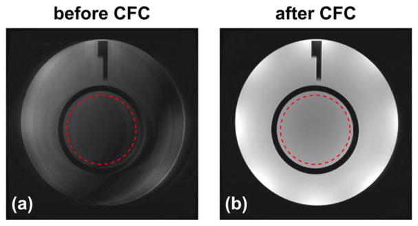
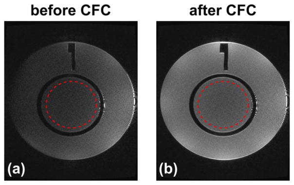
Figure 8 shows examples of the ACR phantom images acquired using a 2D axial FSE acquisition before and after CFC. The SNR values of images before and after CFC were measured from the ROIs (denoted as red circles in Fig. 8) in anatomical and noise images, and are listed in Table 1. The SNR of the CF-compensated images is improved by 4.5 times compared with that before compensation. Examples of the phantom images acquired using a 3D CUBE FLAIR sequence before and after CFC are reformatted into the axial plane and are shown in Figure 9, which demonstrates that a similar signal loss can also be observed in a 3D-FSE acquisition sequence using variable FA long echo train (32), or FSE-based sequence such as FLAIR (33–35). The SNR measurements from the selected ROIs (red circles in Fig. 9) are listed in Table 1, which demonstrates a 1.9-fold improvement after compensation.
FIG. 8.
The ACR phantom images acquired using an axial 2D T2 FSE acquisition before (a) and after (b) the zeroth/first-order CFC. Red circles indicate the ROIs used in SNR measurement provided in Table 1.
Table 1.
Signal-to-Noise Ratio Measurements Before and After CFC From Images Acquired Using 2D Axial FSE and 3D FLAIR Sequences.
| Before CFC | After CFC | |
|---|---|---|
| 2D axial FSE | 31.2 | 140.8 |
| 3D FLAIR | 12.2 | 23.4 |
Note: The SNR is calculated from the ROI (red circles in Figs. 8 and 9) as the ratio between the mean pixel values in the anatomical images and the standard deviation in the noise images, reconstructed by subtracting images acquired subsequently on the same phantom using identical sequence and setup.
FIG. 9.
The ACR phantom images acquired using a 3D T2 FLAIR sequence before (a) and after (b) the zeroth/first-order CFC, and reformatted into the axial plane. Red circles indicate the ROIs used in the SNR measurement provided in Table 1. The ringing at the patient’s left end of the phantom is suspected to be free induction decay artifacts.
DISCUSSION
In this work, we investigate the effect of CF on asymmetric gradient systems in FSE acquisitions, and demonstrate that the additional zeroth/first-order CFs can cause considerable signal loss along the echo train, even with the relatively small FOVs used in standard brain imaging (~20 cm). These asymmetric gradient-specific CFs cause global SNR degradation and dark banding in images. These artifacts can be successfully suppressed using real-time zeroth/first-order CFC. Compared with the strategy limiting the CF effects by reducing gradient amplitude, the methods we demonstrate here are prospective, hardware-implemented techniques that do not require any additional pulse sequence programming or lead to any compromise in imaging performance.
The CF effects are widely known for gradient-intensive, advanced sequences such as phase contrast, EPI, and spiral acquisitions. Here, we demonstrate the necessity of their correction with asymmetric gradients even for routine, anatomical imaging using the “workhorse” FSE or TSE pulse sequences.
Our results also demonstrate interactions between FSE PC and CFs. This is expected, as the phase errors accumulated from different sources can interfere with each other, confounding the correction. Therefore, we suggest that any eddy current characterization process performed on the asymmetric gradients, such the FSE prescan or eddy current calibration, should account for the zeroth and first-order CFs (29,36,37) using pre-emphasis and frequency tracking, respectively.
Because the CFs are quadratically proportional to the gradient amplitude, and because the image signal levels are primary determined by k-space center, the CF effect is expected to be more prominent for a T2-weighted versus T1-weighted FSE, as a result of the longer echo trains. To achieve a T2 contrast, the k-space center is usually acquired using a later echo, with the earlier echoes reserved to acquire the outer regions of k-space (7). Consequently, greater phase errors resulting from higher phase-encoding gradients in earlier echoes can accumulate and propagate into later echoes for T2-weighted acquisitions. Furthermore, a higher spatial resolution in the phase-encoding direction is also expected to have a greater effect. We have also previously observed similar effects in small FOV, high-resolution wrist imaging on our system (38). In contrast, a T1-weighted FSE acquires the k-space center in an earlier echo, and the phase error from the stronger phase-encoding gradients are limited to later echoes, which makes it less susceptible to CFs. We have not observed a noticeable effect in T1-weighted FSE acquisition on our system.
The asymmetry of gradient systems is determined by the asymmetry parameters (i.e., α, x0, y0, z0x, and z0y). The gradient system used in this work has a symmetric z-gradient and asymmetric x- and y-gradients, for which α = 0.5, x0 = y0 = 0, and z0x = z0y = 12cm. The nonzero z0x and z0y indicate that the center of the imaging volume is shifted toward the patient entry side, which is necessary to maintain the compact coil size while giving patient access to imaging volume. The amplitude of the zeroth and first-order CFs is proportional to these parameters, as shown in (25), as well as Equations [2] and [3]. This suggests that a different gradient design (and hence different parameters) can affect the amplitude of different CF terms and the significance of their effects, and needs to be evaluated on a case-by-case basis. Note that the choice of asymmetry is driven primarily by engineering and patient handling considerations (18). Although the CF effect can be reduced by reducing coil asymmetry (e.g., z0), care should be given so that sufficient imaging volume is accessible to patients of different body habitus. Also note that the methods described here assume arbitrary asymmetry parameters, and therefore can be used to analyze and compensate for the CF effect of different asymmetric gradient designs.
The ability to compensate for the additional CF effects for asymmetric gradient coils is even more important and relevant in future, advanced brain microstructure imaging, in which even higher maximum gradient amplitudes are needed. It is not unreasonable to consider advanced head-only gradient coil designs that can achieve maximum gradient amplitudes of up to 200 to 400 mT/m. Under these circumstances, these zeroth and first-order corrections, and possibly higher-order corrections, are necessary to maintain image quality.
This work focuses primarily on the effect and compensation of the zeroth and first-order CFs that are specific to the asymmetric gradient system. Consistent with previous work (12), we confirm that the remaining second-order CFs, which are produced on both asymmetric and conventional symmetric gradients, do not have a significant effect on the brain imaging FOV (~20 cm). However, because the amplitude of the second-order terms scales quadratically with the spatial location (e.g., x2, y2, z2, xz, and yz), the phase error induced by these terms can be strong in large FOV applications such as spine imaging (~48 cm), and can cause similar effects as the zeroth and first-order terms—especially for long echo train, long TE FSE acquisitions. In these cases, pulse sequence modifications such as gradient derating and waveform reshaping (12), or second-order shimming coils (39), can be used to alleviate or compensate for their effects.
CONCLUSIONS
We investigated the CF effect in FSE acquisitions on an asymmetric gradient system, and demonstrated that the zeroth and first-order CFs can cause substantial artifacts, including signal loss and dark bands for brain imaging. These effects can be eliminated successfully using real-time compensation with gradient pre-emphasis and frequency shifting.
Acknowledgments
Grant Support: NIH R01EB010065; NIH 1C06RR18898-01. S.T., P.T.W., J.D.T., Y.S., and M.A.B. have filed a patent application related to the described method.
The authors wish to thank R. Scott Hinks, Louis Frigo, and Leiwei Sha of GE Healthcare for the helpful discussions and technical support.
APPENDIX
Here, we express each operator used in the EPG simulation using a series of matrix operations. The effect of gradient-induced dephasing in a FSE acquisition can be modeled as a shift of transverse configuration states. To precisely express this shifting operator S{·}, we first separate the three rows of the configuration states matrix representing the transverse dephasing, rephasing, and longitudinal states as follows:
| [A1] |
The first two terms in Equation [A1] can be further separated along the column dimension as
| [A2] |
As a result of gradient induced dephasing, the F+(k) are shifted to the right (i.e., F+(k) → F+(k + 1)), representing further dephasing; the F−(k) states are shifted to the left (i.e., F−(k) → F−(k − 1)), representing rephasing; and the Z(k) states remain the same. Mathematically, this shifting operator S{·} can be expressed as the following matrix operations:
| [A3] |
where represents a shift of the first row holding F+(k) to one state higher, except for the last F+(K − 1) term, which is dropped off as it is zero-valued until the end of the last echo and therefore does not contribute. The term denotes a shift of F−(k) (second row of F) to one state lower and fills the last state F−(K − 1) with zero (because F−(k ≥ K) = 0 given the initial condition F0 = δ3[2](δK[0])T). The term ((δ3[0])(δ3[1])TFδK[1])* replaces the current F+(0) state after operation S{·} with the former (F−(1))* before operation, as the F−(1) is now fully refocused to yield echo signal after the action of S{·}. Finally, the δ3[2](δ3[2])TF term remains the same, to leave the Z(k) states as they are.
Similarly, the relaxation operator Eτ,T1,T2{F} can be expressed as
| [A4] |
where the first term represents the relaxation decay processes of transverse and longitudinal states according to T1 and T2 constants, respectively, and the second term denotes the recovery of longitudinal state (Z(0)) toward equilibrium. The T1 and T2 can be chosen based on a particular type of tissue, and the M0 can be chosen as “1” for simplicity.
Finally, the effect of RF pulses can be denoted as a linear rotation matrix operator as follows:
| [A5] |
where φ denotes the initial RF phase angle relative to the x -axis, and θ is the flip angle of this pulse. An RF pulse applied along the x- and y-axis can then be denoted as Tφ=0°,θ and Tφ=90°,θ, respectively.
Footnotes
Some of the results of this work were presented at ISMRM 2017 Annual Meeting.
In accordance with ICMJE guidelines, MAB recused himself from the handling of this paper and all editorial decisions related to it.
References
- 1.Hennig J, Nauerth A, Friedburg H. Rare imaging—a fast imaging method for clinical MR. Magn Reson Med. 1986;3:823–833. doi: 10.1002/mrm.1910030602. [DOI] [PubMed] [Google Scholar]
- 2.Jones KM, Mulkern RV, Mantello MT, Melki PS, Ahn SS, Barnes PD, Jolesz FA. Brain hemorrhage—evaluation with fast spin-echo and conventional dual spin-echo images. Radiology. 1992;182:53–58. doi: 10.1148/radiology.182.1.1727309. [DOI] [PubMed] [Google Scholar]
- 3.Norbash AM, Glover GH, Enzmann DR. Intracerebral lesion contrast with spin-echo and fast spin-echo pulse sequences. Radiology. 1992;185:661–665. doi: 10.1148/radiology.185.3.1438742. [DOI] [PubMed] [Google Scholar]
- 4.Lewin JS, Curtin HD, Ross JS, Weissman JL, Obuchowski NA, Tkach JA. Fast spin-echo imaging of the neck - comparison with conventional spin-echo, utility of fat-suppression, and evaluation of tissue contrast characteristics. Am J Neuroradiol. 1994;15:1351–1357. [PMC free article] [PubMed] [Google Scholar]
- 5.Tien RD, Felsberg GJ. The hippocampus in status epilepticus - demonstration of signal intensity and morphologic changes with sequential fast spin-echo MR-imaging. Radiology. 1995;194:249–256. doi: 10.1148/radiology.194.1.7997562. [DOI] [PubMed] [Google Scholar]
- 6.Hennig J. Multiecho Imaging sequences with low refocusing flip angles. J Magn Reson. 1988;78:397–407. [Google Scholar]
- 7.Bernstein MA, King KF, Zhou XJ. Handbook of MRI pulse sequences. Burlington, MA: Elsevier Academic Press; 2004. [Google Scholar]
- 8.Bernstein MA, Zhou XJ, Polzin JA, King KF, Ganin A, Pelc NJ, Glover GH. Concomitant gradient terms in phase contrast MR: analysis and correction. Magn Reson Med. 1998;39:300–308. doi: 10.1002/mrm.1910390218. [DOI] [PubMed] [Google Scholar]
- 9.Du YP, Zhou XJ, Bernstein MA. Correction of concomitant magnetic field-induced image artifacts in nonaxial echo-planar imaging. Magn Reson Med. 2002;48:509–515. doi: 10.1002/mrm.10249. [DOI] [PubMed] [Google Scholar]
- 10.Zhou XJ, Du YP, Bernstein MA, Reynolds HG, Maier JK, Polzin JA. Concomitant magnetic-field-induced artifacts in axial echo planar imaging. Magn Reson Med. 1998;39:596–605. doi: 10.1002/mrm.1910390413. [DOI] [PubMed] [Google Scholar]
- 11.King KF, Ganin A, Zhou XHJ, Bernstein MA. Concomitant gradient field effects in spiral scans. Magn Reson Med. 1999;41:103–112. doi: 10.1002/(sici)1522-2594(199901)41:1<103::aid-mrm15>3.0.co;2-m. [DOI] [PubMed] [Google Scholar]
- 12.Zhou XJ, Tan SG, Bernstein MA. Artifacts induced by concomitant magnetic field in fast spin-echo imaging. Magn Reson Med. 1998;40:582–591. doi: 10.1002/mrm.1910400411. [DOI] [PubMed] [Google Scholar]
- 13.Roemer PB, inventor. General Electric Company, assignee. Transverse gradient coils for imaging the head. 5,177,442. US Patent. 1993 Jan 5;
- 14.Alsop DC, Connick TJ. Optimization of torque-balanced asymmetric head gradient coils. Magn Reson Med. 1996;35:875–886. doi: 10.1002/mrm.1910350614. [DOI] [PubMed] [Google Scholar]
- 15.vom Endt A, Riegler J, Eberlein E, Schmitt F, Dorbert U, Krüger G, Gruetter R. A high-performance head gradient coil for 7T systems. Proceedings of the 15th Annual Meeting of the ISMRM; Berlin, Germany. 2007; p. 451. [Google Scholar]
- 16.Meier C, Zwanger M, Feiweier T, Porter D. Concomitant field terms for asymmetric gradient coils: consequences for diffusion, flow, and echo-planar imaging. Magn Reson Med. 2008;60:128–134. doi: 10.1002/mrm.21615. [DOI] [PubMed] [Google Scholar]
- 17.O’Brien KR, Kober T, Hagmann P, Maeder P, Marques J, Lazeyras F, Krueger G, Roche A. Robust T1-weighted structural brain imaging and morphometry at 7T using MP2RAGE. PloS One. 2014;9:e99676. doi: 10.1371/journal.pone.0099676. [DOI] [PMC free article] [PubMed] [Google Scholar]
- 18.Lee SK, Mathieu JB, Graziani D, et al. Peripheral nerve stimulation characteristics of an asymmetric head-only gradient coil compatible with a high-channel-count receiver array. Magn Reson Med. 2016;76:1939–1950. doi: 10.1002/mrm.26044. [DOI] [PMC free article] [PubMed] [Google Scholar]
- 19.Chronik BA, Alejski A, Rutt BK. Design and fabrication of a three-axis edge ROU head and neck gradient coil. Magn Reson Med. 2000;44:955–963. doi: 10.1002/1522-2594(200012)44:6<955::aid-mrm18>3.0.co;2-1. [DOI] [PubMed] [Google Scholar]
- 20.Tan ET, Lee SK, Weavers PT, Graziani D, Piel JE, Shu Y, Huston J, III, Bernstein MA, Foo TK. High slew-rate head-only gradient for improving distortion in echo planar imaging: Preliminary experience. J Magn Reson Imaging. 2016;44:653–664. doi: 10.1002/jmri.25210. [DOI] [PMC free article] [PubMed] [Google Scholar]
- 21.Weavers PT, Campeau N, Shu Y, Tao S, Trzasko JD, Gray EM, Foo TKF, Bernstein MA, Huston J., III Improved T2-weighted 3D FLAIR from a compact, lightweight 3T scanner with highperformance gradients. Proceedings of the 25th Annual Meeting of the ISMRM; Honolulu, HI. 2017; p. 4747. [Google Scholar]
- 22.Hennig J, Weigel M, Scheffler K. Calculation of flip angles for echo trains with predefined amplitudes with the extended phase graph (EPG)-algorithm: principles and applications to hyperecho and TRAPS sequences. Magn Reson Med. 2004;51:68–80. doi: 10.1002/mrm.10658. [DOI] [PubMed] [Google Scholar]
- 23.Weigel M. Extended phase graphs: dephasing, RF pulses, and echoes - pure and simple. J Magn Reson Imaging. 2015;41:266–295. doi: 10.1002/jmri.24619. [DOI] [PubMed] [Google Scholar]
- 24.Weavers PT, Tao S, Trzasko JD, Frigo LM, Shu Y, Frick MA, Lee SK, Foo TKF, Bernstein MA. B0 concomitant field compensation for MRI systems employing asymmetric transverse gradient coils. Magn Reson in Med. 2017 doi: 10.1002/mrm.26790. [DOI] [PMC free article] [PubMed] [Google Scholar]
- 25.Tao S, Weavers PT, Trzasko JD, Shu Y, Huston J, III, Lee SK, Frigo LM, Bernstein MA. Gradient pre-emphasis to counteract first-order concomitant fields on asymmetric MRI gradient systems. Magn Reson Med. 2017;77:2250–2262. doi: 10.1002/mrm.26315. [DOI] [PMC free article] [PubMed] [Google Scholar]
- 26.Tao S, Weavers PT, Trzasko JD, Shu Y, Gray EM, Huston J, 3rd, Bernstein MA. Effect of concomitant field in fast spin echo acquisition on an asymmetric MRI gradient system. Proceedings of the 25th Annual Meeting of the ISMRM; Honolulu, HI. 2017; p. 577. [DOI] [PMC free article] [PubMed] [Google Scholar]
- 27.Crozier S, Eccles CD, Beckey FA, Field J, Doddrell DM. Correction of eddy-current-induced B0 shifts by receiver reference-phase modulation. J Magn Reson. 1992;97:661–665. [Google Scholar]
- 28.Weavers PT, Shu Y, Tao S, Huston J, III, Lee SK, Graziani D, Mathieu JB, Trzasko JD, Foo TK, Bernstein MA. Technical note: Compact three-tesla magnetic resonance imager with high-performance gradients passes ACR image quality and acoustic noise tests. Med Phys. 2016;43:1259–1264. doi: 10.1118/1.4941362. [DOI] [PMC free article] [PubMed] [Google Scholar]
- 29.Hinks RS, inventor. General Electric Company, assignee. Fast spin echo prescan for MRI system. US5378985 A. US Patent. 1995
- 30.Tao S, Trzasko JD, Shu Y, Huston J, III, Bernstein MA. Integrated image reconstruction and gradient nonlinearity correction. Magn Reson Med. 2015;74:1019–1031. doi: 10.1002/mrm.25487. [DOI] [PMC free article] [PubMed] [Google Scholar]
- 31.Tao S, Trzasko JD, Shu Y, Weavers PT, Huston J, III, Gray EM, Bernstein MA. Partial Fourier and parallel MR image reconstruction with integrated gradient nonlinearity correction. Magn Reson Med. 2016;75:2534–2544. doi: 10.1002/mrm.25842. [DOI] [PMC free article] [PubMed] [Google Scholar]
- 32.Mugler JP. Optimized three-dimensional fast-spin-echo MRI. J Magn Reson Imaging. 2014;39:745–767. doi: 10.1002/jmri.24542. [DOI] [PubMed] [Google Scholar]
- 33.Kallmes DF, Hui FK, Mugler JP. Suppression of cerebrospinal fluid and blood flow artifacts in FLAIRMR imaging with a single-slab three-dimensional pulse sequence: initial experience. Radiology. 2001;221:251–255. doi: 10.1148/radiol.2211001712. [DOI] [PubMed] [Google Scholar]
- 34.Chagla GH, Busse RF, Sydnor R, Rowley HA, Turski PA. Three-dimensional fluid attenuated inversion recovery imaging with isotropic resolution and nonselective adiabatic inversion provides improved three-dimensional visualization and cerebrospinal fluid suppression compared to two-dimensional flair at 3 tesla. Invest Radiol. 2008;43:547–551. doi: 10.1097/RLI.0b013e3181814d28. [DOI] [PMC free article] [PubMed] [Google Scholar]
- 35.Hajnal JV, Bryant DJ, Kasuboski L, Pattany PM, Decoene B, Lewis PD, Pennock JM, Oatridge A, Young IR, Bydder GM. Use of fluid attenuated inversion recovery (FLAIR) pulse sequences in MRI of the brain. J Comput Assist Tomo. 1992;16:841–844. doi: 10.1097/00004728-199211000-00001. [DOI] [PubMed] [Google Scholar]
- 36.Jehenson P, Westphal M, Schuff N. Analytical method for the compensation of eddy-current effects induced by pulsed magnetic-field gradients in NMR systems. J Magn Reson. 1990;90:264–278. [Google Scholar]
- 37.Van Vaals JJ, Bergman AH. Optimization of eddy-current compensation. J Magn Reson. 1990;90:52–70. [Google Scholar]
- 38.Weavers PT, Frick M, Gray EM, Stanley D, Trzasko JD, Tao S, Shu YDD, Huston J, III, Foo TKF, Bernstein MA. Musculoskeletal imaging of the extremities with a compact 3T MRI with high-performance gradients. Proceedings of the 25th Annual Meeting of the ISMRM; Honolulu, HI. 2017; p. 5029. [Google Scholar]
- 39.Sica CT, Meyer CH. Concomitant gradient field effects in balanced steady-state free precession. Magn Reson Med. 2007;57:721–730. doi: 10.1002/mrm.21183. [DOI] [PubMed] [Google Scholar]


