Abstract
High-throughput imaging and screening is essential for biomedical research and drug discovery using miniature model organisms such as zebrafish. This study introduces a high-speed imaging system which illuminates zebrafish embryos flowing through a capillary tube with a sheet of light and captures them using a linear charge-coupled device (CCD). This system can image dozens of zebrafish embryos per second. An image algorithm was developed to recognize each embryo and to perform automatic analysis. We distinguished dead and living embryos according to the gray level distribution and conducted statistics of morphological characteristics of embryos at different growing stages.
OCIS codes: (170.0110) Imaging systems, (170.0170) Medical optics and biotechnology, (170.3880) Medical and biological imaging
1. Introduction
Zebrafish are an important vertebrate model for life science research and drug discovery. It affords the advantages of transparency and a human-like organ system, and thus, the results of analyses of pharmacological effects and genetic changes in zebrafish can be extended to humans [1–3]. To achieve further developments in modern biology and microbiotechnology, high-throughput screening requires the imaging and analysis of a large number of biological samples. For this purpose, high-speed biometric imaging systems that can produce thousands of high-resolution zebrafish embryo images are needed [4–6]. However, traditional manually operated microscopes have low speed and large workload, making them unsuitable for high-throughput imaging.
In cell biology studies, high-throughput cell screening is performed using flow cytometers for automatically analyzing and sorting cells. Recently, imaging flow cytometers have been developed for imaging each cell in a flow [7, 8]. Then, the statistics of cell morphology can be deduced to differentiate cell types or to study the dynamics [9–11]. A microfluidics-based flow cytometer has also been developed in recent years; this is in principle a microscopic imager of the microfluidic channel [12, 13]. Although all of the above instruments are useful for high-throughput cell imaging, they cannot be applied to miniature model organisms such as zebrafish because their embryos are hundreds of times larger than normal cells, and therefore, the microfluidic channel needs to be wider and the imaging field of view needs to be larger.
Union Biometrica developed a Complex Object Parametric Analyzer and Sorter (COPAS) for the high-throughput screening of vertebrate models with sample size of 10–1500 μm. However, it cannot capture images of model animals; this limits its screening accuracy and field of applications. Pardo-Martin et al. developed a Vertebrate Automated Screening Technology (VAST) system that can automatically load, position, and rotate zebrafish larvae under a commercial confocal system [14, 15]. This system can capture high-profile images of each Zebrafish embryo within 9.6 s, thus greatly improving the screening accuracy and efficiency.
This study proposes a high-speed zebrafish embryo imaging method using a flow imaging scheme. This system used a fast linear charge-coupled device (CCD) to capture images of zebrafish embryos flowing through a capillary. Accordingly, a thin sheet of light was generated using a cylinder lens and illuminated on the samples to reduce the exposure of the living embryos to the laser [16–18]. Line-scan imaging has been widely used for pathological slide scanning. Similar geometry was also used to image cells or C.elegans in microfluidic channel [19–23]. However, to the best of our knowledge, this is the first time it has been used for imaging living embryos in a fluidic flow. Up to 20 embryos can be imaged in a second; this is 100 times faster than the VAST system. We also developed algorithms for the automatic analysis of embryos with and without chorion. Dead and live embryos can be distinguished by their gray level distribution, and this method can be used to study the effect of temperature on the cumulative mortality rate. The analysis of the morphological characteristics of zebrafish embryos (i.e., their lengths and widths) is also demonstrated. Our linear-CCD-based flow imaging system (Lc-FIS) is promising for large-scale studies of the development of miniature model organisms in terms of various factors and drug discovery.
2. Materials and methods
2.1 Lc-FIS imaging principle
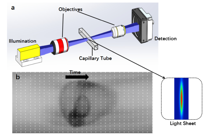
Traditional imaging systems for zebrafish embryos, such as stereomicroscopes, use array-CCD cameras to record optical signals. The imaging speed is limited by the camera itself and the process involves positioning the sample in the field of view, and therefore, high-throughput automatic imaging of Zebrafish embryos cannot be achieved. Similar to imaging flow cytometry, we developed an Lc-FIS in which the embryos flow through a capillary tube. A cross section of the tube was illuminated with a sheet of light and a linear-CCD camera was used to record the transmission signal continuously (Fig. 1(a)). Arranging the time series 1D array data into a 2D array image will show the entire embryo’s morphology as it flows through (Fig. 1(b)). Owing to the high speed of the linear-CCD camera (up to 66 kHz), the imaging speed is limited by the flow speed instead of the camera.
Fig. 1.
Principle of Lc-FIS. (a) A sheet of light was focused by an objective to illuminate the section of a capillary tube while embryos flowed through. The transmitted light signal was recorded by a fast linear CCD at the other side of the tube. Inset shows the intensity profile of the light sheet at focus plane. (b) Arranging time series 1D linear CCD data into a 2D image. The black arrow indicates the flow direction.
2.2 Sample loading and fluidics
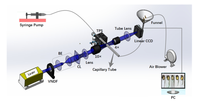
Zebrafish embryos need to be loaded and flow through a capillary in Lc-FIS (Fig. 2). A 0.5-L funnel was used as a reservoir, with its outlet connected to a silicon tube (inner diameter: 2 mm). Approximately 0.4 L of incubation media with 100–400 zebrafish embryos filled in the reservoir to load the samples. By using a larger funnel, the volume could be increased easily. To prevent the embryos from blocking the outlet, an air blower (XPOWER A-2 Airrow, XPOWER) was used to blow bubbles into the funnel. The flow was driven by a syringe pump (SPLab01, Shenzhen Peristaltic Pump) at the other end of the tube. The flow speed can be controlled precisely by using the syringe pump. A rectangular glass capillary (inner diameter: 1.6 mm, outer diameter: 1.9 mm) was inserted between the silicon tubes for imaging. This capillary was mounted on a three-axis position stage (MPC-200, Sutter Instrument Company) to position it at the focus of the objective.
Fig. 2.
Schematic illustration of Lc-FIS. In the fluidic part, samples were loaded to a funnel reservoir and driven through a capillary tube by a stable syringe pump. Air blower was used to prevent blocking. In the imaging part, a light sheet created by a cylindrical lens was focused on the center of capillary tube perpendicularly. Transmitted light signal was recorded by a linear CCD. VNDF, variable neutral density filter; BE, beam expander; CL, cylindrical lens; TPS, three-axis position stage.
2.3 Light sheet illumination and linear-CCD imaging
For light sheet illumination, a 561-nm laser (Coherent, Changchun New Industries Optoelectronics) was first expanded by a pair of lenses (f = 50 mm and f = 300 mm) and a light sheet was created by a cylindrical lens (f = 10 mm, LJ1878L1-A, Thorlabs). A tube lens (f = 100 mm, AC254-100-A, Thorlabs) and a 10 × objective (NA = 0.4) focused the light sheet on the center of the rectangular capillary tube. The light sheet is perpendicular to the capillary tube. By installing a beam profiler in the focus plane, the intensity profile of the light sheet was characterized. Length of the light sheets was measured to be 1.5 mm and the thickness was 4 μm (FWHM). The transmitted light signal was collected by a 4 × objective (NA = 0.15) and imaged by a tube lens (f=80 mm,AC254-80-A,Thorlabs) to a high-speed linear CCD camera (Ral12288-66km, Basler). The linear CCD has a pitch size of 3.5 μm and total pixel number of 12288; it could acquire 66000 lines per second, corresponding to a exposure time of 15 µs.
2.4 Culture of zebrafish embryos
Adult zebrafish were raised and maintained at 28.5°C. The embryos were obtained by natural spawning of wild adult fish. The zebrafish embryos were incubated in E3 medium (5 mM NaCl, 0.17 mM KCl, 0.33 mM CaCl2, and 0.33 mMMgSO4). The chorion was removed via proteolytic enzyme treatment 72 h post-fertilization (hpf). Lc-FIS took about 20-30 ms to a dechorionated zebrafish with length of 2-3mm. Even during this short time, awake zebrafishes are still expected to move which blur the recorded image. In order to prevent that, the embryos were anesthetized with 0.2 mg·ml−1 Tricaine.
3. Results
3.1 Real-time imaging of zebrafish embryos using Lc-FIS
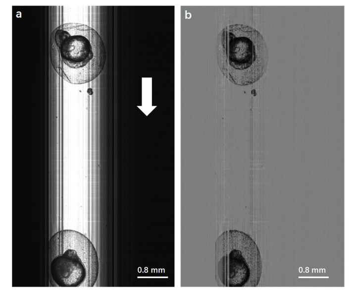
Lc-FIS can capture images of zebrafish embryos flowing through a capillary, as shown in Fig. 3(a). The brighter part of Fig. 3(a) is the capillary tube illuminated by the light sheet. The light sheet has a Gaussian beam distribution along the x-axis, which is perpendicular to the capillary tube. The linear CCD was positioned precisely along the light sheet beam to capture the transmitted signal. The continually captured 1D data were stacked according to time to form 2D image with length dependent on the recording time. The vertical strips may be due to some dirt from the solution sticking on the capillary wall. The background and strips could be removed by subtracting an average of 10 lines data (excluding the embryo region) from the original image, as shown in Fig. 3(b). Two zebrafish embryos with chorion were seen clearly. The same image preprocessing was applied to all other figures.
Fig. 3.
(a) Original image of zebrafish embryos obtained by Lc-FIS. The white arrow indicates the flow direction. (b) Preprocessed image after substracting the background.
In Lc-FIS, the embryos were exposed to the laser only when they passed through the light sheet, and therefore, the photon toxicity is negligible. Over 98% of the embryos imaged by Lc-FIS survive and develop without noticeable morphological abnormalities. The remaining 2% of abnormal embryos are more likely due to the effect of the liquid flow rather than laser exposure, which can be further decreased by optimizing the fluidics.
3.2 Automatic segmentation of zebrafish embryos (10–24 hpf) with chorion
By using Lc-FIS, thousands of zebrafish embryos could be imaged in a few minutes, thus allowing statistical analyses of various characteristics of embryos. For statistics, the segmentation of each embryo from the data is required. We first demonstrate the segmentation of zebrafish embryo with chorion (10–24 hpf).
The chorion forms a clear circle around the embryos. Therefore, we use a Hough transformation algorithm to define a circle along the edge of the chorion [24, 25]. The radius R0 = 0.8 mm was set as the initial parameter, and the radius is limited in the range of 0.5–2R0. The minimum distance between the circles was limited to R0/5 to avoid overlapped circles. In a set of data captured using Lc-FIS in 7s, 100 zebrafish embryos were checked manually by the eyes. Of these, 93 embryos were detected successfully by our algorithm. The seven undetected embryos were either stuck together or had an abnormal shape (chorion broken).
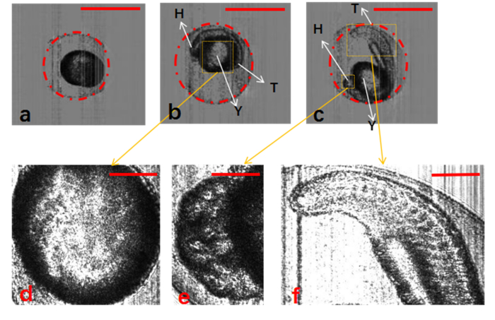
The morphology of the organs of zebrafish embryos can be seen clearly in the Lc-FIS images, and this can be used to check their development condition. According to the development stage definition [26–30], the embryos in the early stage had smaller chorions (Fig. 4(a), 2.6 hpf) and those in the later stage had chorions of similar size (Fig. 4(b), 13 hpf; Fig. 4(c), 21.5 hpf). The yolk, head, and tail can be seen clearly in Figs. 4(b) and 4(c). Figure 4(d)–4(f) show magnified view of these figures. In Fig. 4(d), the yolk sac of the embryo is clear and transparent. According to the development stage definition, the embryo shown in Fig. 4(c) is in the somite stage. Figure 4(e) shows the head bulging with numerous vesicles, and Fig. 4(f) shows the somite along the tail curvature.
Fig. 4.
Segmentation of zebrafish embryos with chorion using Hough-transformation circle detection algorithm. (a–c) Zebrafish embryos at different development stages: 3, 13, and 21.5 hpf, respectively. (d–f) Detailed structure of yolk, head, and tail of zebrafish embryos. H, head; T, tail; Y, yolk. The scale bars in (a)–(c) represent 1 mm, and those in (d)–(f) represent 0.3 mm.
3.3 Embryo mortality analysis
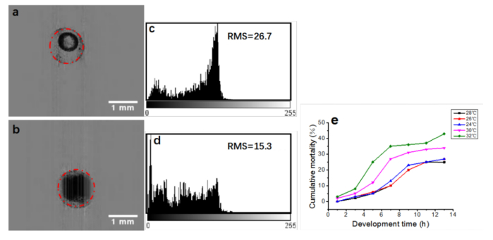
Lc-FIS imaging and automatic segmentation of zebrafish embryos with chorion could be used for obtaining statistics on embryos mortality. Figure 5 shows a live embryo and a dead embryo. The liquid in a living embryo is clear (Fig. 5(a)) whereas that in a dead embryo is murky (Fig. 5(b)). Thus, dead embryos can be identified by analyzing the gray level distributions of embryos [31]. In general, the gray level distribution of a normally developed embryo is triangular, where the middle part has a raised wave crest and the sides are evenly distributed; the intensity root-mean-square (RMS) within the circle is 26.7, as shown in Fig. 5(c). However, the fluctuation range of the gray level distribution of a dead embryo is small, and there is no raised wave crest in the middle part of the distribution; the intensity RMS of this embryo is 15.4, as shown in Fig. 5(d). A RMS threshold of 21.0 was set to discriminate live and dead embryos. We used the method to identify dead embryos by using Lc-FIS to image 400 embryos, which took 30 s.
Fig. 5.
Discrimination of live and dead embryos by Lc-FIS. (a) Normal and (b) dead embryos (4 hpf) detected using the Hough-transformation algorithm. (c) and (d) Intensity distributions within the circle of the live and dead embryos, respectively. (e) Cumulative mortality rate of zebrafish embryos at temperatures of 24°C, 26°C, 28°C, 30°C, and 32°C.
After identifying the dead embryos among numerous samples, we studied the effect of temperature on the cumulative mortality rate of the zebrafish embryos (1–13 hpf). We performed five sets of experiments using 400 zebrafish embryos. The embryos were automatically imaged, segmented, discriminated live or dead, and counted. The zebrafish embryos were incubated at different temperatures in each experiment: 24°C, 26°C, 28°C, 30°C, and 32°C. The number of dead embryos was counted by Lc-FIS every 2 h. Then, their cumulative mortality rate during the 13 h growth period was calculated. The experimental results presented in Fig. 5(e) indicate that the cumulative mortality rate varies with time. The cumulative mortality rate of the embryos increases in the following order: 28°C, 26°C, 24°C, 30°C, 32°C. The more the temperature deviates from the optimum temperature, the higher is the mortality rate, as shown in Fig. 5(e).
3.4 Segmentation of dechorionated zebrafish embryos (72 hpf)
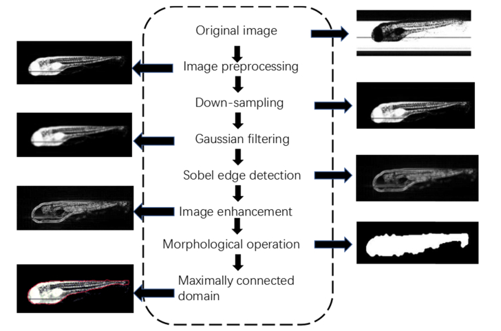
We further imaged and analyzed zebrafish embryos without chorion (72 hpf) using Lc-FIS. Without chorion, segmentation algorithms based on Hough transformation are no-longer effective. Instead, we used edge detection and morphological operations to obtain the region of embryos from Lc-FIS images. Figure 6 shows the flowchart of the segmentation process.
Fig. 6.
Flowchart of segmentation for zebrafish embryos without chorion.
The original image obtained by Lc-FIS was first preprocessed to remove the background and illumination nonuniformities. Then, it was smothered by 4x down sampling and 5x5 Gaussian filtering to remove sharp noises. Sobel edge detection was then applied to find sharp variances in the image. To enhance the edge detection accuracy, the Sobel gradient operator was applied in four directions:
| (1) |
where G45° = [-2 −1 0; −1 0 1; 0 1 2] and G135° = [0 −1 −2; 1 0 −1; 2 1 0] along the diagonal direction [32,33]. The edges were further enhanced by Wiener filtering, and then, morphological operations were applied to deduce the contour shape [34–37]. Finally, the region was connected to a single domain as the morphology of zebrafish embryos.
3.5 Statistics of dechorionated zebrafish embryo morphology
Figure 7(a) shows a typical preprocessed image of a dechorionated zebrafish embryo. The embryos were in the protruding-mouth stage, 72 hpf. Figure 7(b) shows its segmentation result; this result was used to deduce the body characteristics of the zebrafish embryos. Here, we define the embryo length (EL) and embryo width (EW) to characterize the developmental condition. EL refers to the longest linear dimension of the embryo and EW, to the maximum linear width perpendicular to the EL direction [26]. Other more detailed parameters could also be deduced from the segmented images obtained using Lc-FIS.
Fig. 7.
Morphology statistics of live zebrafish embryos (72 hpf) without chorion. (a) Preprocessed image after subtracting background from the original image. (b) Binary image obtained after segmentation. The vertical and horizontal arrows indicate the EL and EW, respectively. (c) EL and (d) EW distributions of 100 zebrafish embryos (72 hpf). H, head; F, fin; I, intestine; S, somites; Y, yolk. The scale bars in (a) and (b) represent 1 mm
A total of 100 dechorionated zebrafish embryos were imaged using Lc-FIS; this took ~7 s. The EL and EW of each embryo were determined using the above-described algorithms. Figure 7(c) shows that EL has a Gaussian distribution with average length of 2.5 mm and FWHM of 0.03 mm. The distribution of EW does not show a Gaussian shape, possibly because of the orientation of embryos flowing through the capillary. Because FIS records only the projection in the perpendicular plane, embryos with different rotations will yield different EW whereas EL will not be affected. Embryos whose actual maximum width is not at the image plane tend to have smaller measured EW. Therefore, the most likely EW value represents the actual embryo width, which is 0.5 mm. It is noted that six embryos show much larger width of ~0.6 mm for unknown reasons. Nevertheless, our results clearly demonstrate developmental asynchrony even in zebrafish embryos that were fertilized simultaneously in vitro and incubated under the same optimal conditions.
4. Discussion
We introduced the high-speed Lc-FIS system for imaging zebrafish embryos, in which embryos flowing through a capillary tube were illuminated by a light sheet and imaged by a linear CCD. Lc-FIS can image more than 10 embryos per second at optimized condition. Compared to the VAST system, which requires 9.6 s to image one larva, the Lc-FIS is 100 times faster.
The imaging speed of Lc-FIS is limited to the flow rate rather than on the camera speed. The flowing speed of embryos Vl and number of embryos processed per second N can be respectively formulated as
| (2) |
and
| (3) |
where dem is the mean zebrafish embryo length; Scap, the cross-sectional area of the square capillary; and Vv, the volumetric velocity of the flow; in this study, their values were optimized as 1.5 mm, 2.56 mm2, and 2.3 × 10⁻⁷ m3·s−1, respectively. The speed is slow enough to not affect the development condition of flowing embryos. To avoid the overlapping of embryos, the distance between samples ldis was set as three times the embryo length:
| (4) |
According to these equations and numbers, Lc-FIS should be able to image 20 embryos per second. In practice, we generally imaged 5–15 embryos per second.
The vertical resolution RV of Lc-FIS is also dependent on Vl and the rate of the linear CCD. In our experiments, Vl was 0.09 m·s−1, and f was set as 66000 frames per second. The horizontal resolution remains the same regardless of these values, and RV is given by the following relationship:
| (5) |
The corresponding Rv is ~1.35 μm, which is smaller than the width of the light sheet beam. In Lc-FIS, a 4 μm thick Light sheet illumination was used in order to reduce the exposure of the living embryos to the laser. The time of embryos exposed the laser would be 375 times longer when flowing through the capillary if a gaussian beam with diameter was used instead. So, the image process of Lc-FIS itself did not show a noticeable effect on the viability of embryos.
In order to yield high throughput, a tradeoff has been made to image resolution in Lc-FIS. Along flow direction, increasing the flow speed will yield high throughput but also lower the resolution and cause the embryos to begin overlapping. In order to get large field of view, a low-magnification objective was used for collecting signal. Using a linear CCD with 3.5 μm pitch size and 4x objective yields 0.875 μm per pixel in the final image along CCD direction. However, the final image resolution depends on the numerical aperture of the collection objective instead of CCD pixel size and flow speed. In theory, resolution of an objective is determined by:
| (6) |
where is the wavelength of the illuminating beam and NA is the numerical aperture of the collection objective. This results an overall the resolution of 2.3 μm for Lc-FIS.
Because the embryos are imaged through a capillary in Lc-FIS, the generally used circular capillary acts as a lens and causes severe aberration. To achieve distortion-free, low-background imaging, a square capillary (inner diameter: 1.6 mm, outer diameter: 1.9 mm) was used in Lc-FIS. Our results indicated that the square capillary produced significantly less image distortion than the circular capillary.
It should be noted that Lc-FIS imaging relies on a constant flow velocity. Within the capillary tube, the flow speed near the wall is expected to be smaller than the speed at the center. In fact, we observed that the 1 μm nanoparticles flow faster at the center; this caused a distortion in the final image. However, this phenomenon is not observed for zebrafish embryos. This could be because the size of zebrafish embryos is comparable to the inner diameter of the capillary tube, and therefore, the movement of these embryos is dominated by the flow at the capillary center.
Because Lc-FIS only records a projection image, dechorionated zebrafish embryos with different rotations will appear to be different in the final image. This should be kept in mind for statistics and for interpreting the measured results. To obtain more accurate results, 3D imaging should be performed by either confocal microscopy or rotated light sheet imaging. However, this will make the imaging system more complex and time-consuming. Nevertheless, the current Lc-FIS could already provide much information on the morphology of zebrafish embryos.
We demonstrate the application of Lc-FIS to study the temperature-dependent cumulative mortality rate of zebrafish embryos with chorions and the developmental asynchrony of embryos without chorions. We believe that this system can be used for more complex biological characterization of zebrafish, for example, to study the effects of drugs or genes on the development of zebrafish embryos [38]. Detailed zebrafish embryo images can be used to assess whether an embryo is normal. Specifically, abnormalities in the eyes, brain, and somites can be detected by observing their sizes and gray level variations. However, to observe finer structures such as neural and cardiovascular system, resolution of Lc-FIS is not sufficient. The resolution could be improved by using a higher NA objective for the purpose.
The Lc-FIS records transmitted light amplitudes as a contrast. In future work, phase contrast and fluorescent imaging modalities can be incorporated into this system to obtain more information. Then, it could be used for studying morphology changes as well as tissue ingredients, gene expressions, and mutations, and so on.
Lc-FIS can be further extended to work as an embryo sorting device. According to recognition results, different types of zebrafish embryos will be sorted into a multiwell plate by using a three-axis motor stage. This sorting device will first be used to separate dead embryos from live ones. More importantly, it will facilitate the rapid acquisition of different types of zebrafish embryos and promote the large-scale application of vertebrate animal models in biomedicine.
5. Conclusions
In conclusion, we have demonstrated a high-speed fluidic imaging system, Lc-FIS, that is similar to an imaging cytometer in principle but primarily intended for zebrafish embryos instead of cells. Lc-FIS can image up to 20 embryos per second, which is 100 times faster than the previously reported VAST system. Furthermore, we developed image recognition algorithms to segment embryos with/without chorions. The proposed system and algorithms were used to study the temperature-dependent cumulative mortality rate and development asynchronization of zebrafish embryos. Our system and methods will satisfy the demanding for high-throughput analysis in developmental biology and drug discovery studies.
Funding
This work was supported by the Natural Science Foundation of China (NSFC) (Grant Nos. 61475185, 61405237, and 61405238), Natural Science Foundation of Jiangsu Province (Grant No. BK20141206), scientific research equipment development project of the Chinese Academy of Sciences (Grant No. YZ201646), and Hundred-Talent Program of the Chinese Academy of Sciences.
Disclosures
The authors declare that there are no conflicts of interest related to this article.
References and links
- 1.Zon L. I., Peterson R. T., “In vivo drug discovery in the zebrafish,” Nat. Rev. Drug Discov. 4(1), 35–44 (2005). [DOI] [PubMed] [Google Scholar]
- 2.Hill A. J., Teraoka H., Heideman W., Peterson R. E., “Zebrafish as a model vertebrate for investigating chemical toxicity,” Toxicol. Sci. 86(1), 6–19 (2005). [DOI] [PubMed] [Google Scholar]
- 3.Li D., Zhao X., Qin W., “Toxicity assessment and long-term three-photon fluorescence imaging of bright aggregation-induced emission nanodots in zebrafish,” Nano Res. 9(7), 1921–1933 (2016). [Google Scholar]
- 4.Giacomotto J., Ségalat L., “High-throughput screening and small animal models, where are we?” Br. J. Pharmacol. 160(2), 204–216 (2010). [DOI] [PMC free article] [PubMed] [Google Scholar]
- 5.Ellertsdóttir E., Lenard A., Blum Y., Krudewig A., Herwig L., Affolter M., Belting H. G., “Vascular morphogenesis in the zebrafish embryo,” Dev. Biol. 341(1), 56–65 (2010). [DOI] [PubMed] [Google Scholar]
- 6.Kissa K., Herbomel P., “Blood stem cells emerge from aortic endothelium by a novel type of cell transition,” Nature 464(7285), 112–115 (2010). [DOI] [PubMed] [Google Scholar]
- 7.Han Y., Gu Y., Zhang A. C., Lo Y. H., “Review: imaging technologies for flow cytometry,” Lab Chip 16(24), 4639–4647 (2016). [DOI] [PMC free article] [PubMed] [Google Scholar]
- 8.Basiji D. A., Ortyn W. E., Liang L., Venkatachalam V., Morrissey P., “Cellular image analysis and imaging by flow cytometry,” Clin. Lab. Med. 27(3), 653–665 (2007). [DOI] [PMC free article] [PubMed] [Google Scholar]
- 9.Cosette J., Moussy A., Paldi A., Stockholm D., “Combination of imaging flow cytometry and time-lapse microscopy for the study of label-free morphology dynamics of hematopoietic cells,” Cytometry A 91(3), 254–260 (2017). [DOI] [PubMed] [Google Scholar]
- 10.Wortzel I., Koifman G., Rotter V., Seger R., Porat Z., “High Throughput Analysis of Golgi Structure by Imaging Flow Cytometry,” Sci. Rep. 7(1), 788–802 (2017). [DOI] [PMC free article] [PubMed] [Google Scholar]
- 11.Goda K., Ayazi A., Gossett D. R., Sadasivam J., Lonappan C. K., Sollier E., Fard A. M., Hur S. C., Adam J., Murray C., Wang C., Brackbill N., Di Carlo D., Jalali B., “High-throughput single-microparticle imaging flow analyzer,” Proc. Natl. Acad. Sci. U.S.A. 109(29), 11630–11680 (2012). [DOI] [PMC free article] [PubMed] [Google Scholar]
- 12.Lau A. K., Shum H. C., Wong K. K., Tsia K. K., “Optofluidic time-stretch imaging - an emerging tool for high-throughput imaging flow cytometry,” Lab Chip 16(10), 1743–1896 (2016). [DOI] [PubMed] [Google Scholar]
- 13.Zeng Y., Xu J., Li D., Li L., Wen Z., Qu J. Y., “Label-free in vivo flow cytometry in zebrafish using two-photon autofluorescence imaging,” Opt. Lett. 37(13), 2490–2492 (2012). [DOI] [PubMed] [Google Scholar]
- 14.Pardo-Martin C., Chang T.-Y., Koo B. K., Gilleland C. L., Wasserman S. C., Yanik M. F., “High-throughput in vivo vertebrate screening,” Nat. Methods 7(8), 634–636 (2010). [DOI] [PMC free article] [PubMed] [Google Scholar]
- 15.Chang T.-Y., Pardo-Martin C., Allalou A., Waehlby C., Yanik M. F., “Fully automated cellular-resolution vertebrate screening platform with parallel animal processing,” Lab Chip 12(4), 711–716 (2013). [DOI] [PMC free article] [PubMed] [Google Scholar]
- 16.Huisken J., Swpger J., Del B. F., Wittbrodt J., Stelzer E. H., “Optical sectioning deep inside live embryos by selective plane illumination microscopy,” Science 305(5686), 1007–1009 (2004). [DOI] [PubMed] [Google Scholar]
- 17.Panier T., Romano S. A., Olive R., Pietri T., Sumbre G., Candelier R., Debregeas G., “Fast functional imaging of multiple brain regions in intact zebrafish larvae using selective plane illumination microscopy,” Front. Neural Circuits 7, 65 (2013). [DOI] [PMC free article] [PubMed] [Google Scholar]
- 18.Regmi R., Mohan K., Mondal P. P., “Light sheet based imaging flow cytometry on a microfluidic platform,” Microsc. Res. Tech. 76(11), 1101–1107 (2013). [DOI] [PubMed] [Google Scholar]
- 19.Poon T. C., “Optical Scanning Holography: Principles” in: Optical Scanning Holography with MATLAB. Springer, Boston, MA: (2007). [Google Scholar]
- 20.Pégard N. C., Toth M. L., Driscoll M., Fleischer J. W., “Flow-scanning optical tomography,” Lab Chip 14, 4447–4450 (2014). [DOI] [PMC free article] [PubMed] [Google Scholar]
- 21.Bianco V., Paturzo M., Ferraro P., “Spatio-temporal scanning modality for synthesizing interferograms and digital holograms,” Opt. Express 22(19), 22328–22339 (2014). [DOI] [PubMed] [Google Scholar]
- 22.Bianco V., Paturzo M., Marchesano V., Gallotta I., Di Schiavi E., Ferraro P., “Optofluidic holographic microscopy with custom field of view (FoV) using a linear array detector,” Lab Chip 15(9), 2117–2124 (2015). [DOI] [PubMed] [Google Scholar]
- 23.Mandracchia B., Bianco V., Wang Z., Mugnano M., Bramanti A., Paturzo M., Ferraro P., “Holographic microscope slide in a spatio-temporal imaging modality for reliable 3D cell counting,” Lab Chip 17(16), 2831–2838 (2017). [DOI] [PubMed] [Google Scholar]
- 24.Ulrich M., Steger C., Baumgartner A., “Real-time object recognition using a modified generalized Hough transform,” Pattern Recognit. 36(11), 2557–2570 (2003). [Google Scholar]
- 25.Shi P., Huang Y., Hong J., “Automated three-dimensional reconstruction and morphological analysis of dendritic spines based on semi-supervised learning,” Biomed. Opt. Express 5(5), 1541–1553 (2014). [DOI] [PMC free article] [PubMed] [Google Scholar]
- 26.Kimmel C. B., Ballard W. W., Kimmel S. R., Ullmann B., Schilling T. F., “Stages of embryonic development of the zebrafish,” Dev. Dyn. 203(3), 253–310 (1995). [DOI] [PubMed] [Google Scholar]
- 27.Li L., Yan B., Shi Y. Q., Zhang W. Q., Wen Z. L., “Live imaging reveals differing roles of macrophages and neutrophils during zebrafish tail fin regeneration,” J. Biol. Chem. 287(30), 25353–25360 (2012). [DOI] [PMC free article] [PubMed] [Google Scholar]
- 28.zur Nieden N. I., Davis L. A., Rancourt D. E., “Comparing three novel endpoints for developmental osteo toxicity in the embryonic stem cell test,” Toxicol. Appl. Pharmacol. 247(2), 91–97 (2010). [DOI] [PubMed] [Google Scholar]
- 29.Cheng K. C., Xin X., Clark D. P., La Riviere P., “Whole-animal imaging, gene function, and the Zebrafish Phenome Project,” Curr. Opin. Genet. Dev. 21(5), 620–629 (2011). [DOI] [PMC free article] [PubMed] [Google Scholar]
- 30.Zhang J., Liss M., Wolburg H., Blasig I. E., Abdelilah-Seyfried S., “Involvement of claudins in zebrafish brain ventricle morphogenesis,” Ann. N. Y. Acad. Sci. 1257(1), 193–198 (2012). [DOI] [PubMed] [Google Scholar]
- 31.Weidinger G., Stebler J., Slanchev K., Umstrei K. D., Wise C., Lovelladge R., Thisse C., Thisse B., Raz E., “Dead end, a novel vertebrate germ plasm component, is required for zebrafish primordial germ cell migration and survival,” Curr. Biol. 13(16), 1429–1434 (2003). [DOI] [PubMed] [Google Scholar]
- 32.Klimaschewski L., Nindl W., Pimpl M., Waltomger P., Pfaller K., “Biolistic transfection and morphological analysis of cultured sympathetic neurons,” J. Neurosci. Methods 113(1), 63–71 (2002). [DOI] [PubMed] [Google Scholar]
- 33.Benali A., Leefken I., Eysel U. T., Weiler E., “A computerized image analysis system for quantitative analysis of cells in histological brain sections,” J. Neurosci. Methods 125(1/2), 33–43 (2003). [DOI] [PubMed] [Google Scholar]
- 34.Su J. H., Xing M. D., Bao Z., “Wideband radar detection for maneuvering target,” J. Electron. Inform. Technol. 31(6), 1283–1287 (2009). [Google Scholar]
- 35.Perry R. P., DiPietro R. C., Fante R. L., “SAR imaging of moving targets,” IEEE Trans. Aerosp. Electron. Syst. 35(1), 188–200 (1999). [Google Scholar]
- 36.Zhu D., Li Y., Zhu Z., “A keystone transform without interpolation for SAR ground moving target imaging,” IEEE Geosci. Remote 18-22(1), 4 (2007). [Google Scholar]
- 37.Warga R. M., Kimmel C. B., “Cell movements during epiboly and gastrulation in zebrafish,” Development 108(4), 569–580 (1990). [DOI] [PubMed] [Google Scholar]
- 38.Kim K. T., Zaikova T., Hutchison J. E., Tanguay R. L., “Gold nanoparticles disrupt zebrafish eye development and pigmentation,” Toxicol. Sci. 133(2), 275 (2013). [DOI] [PMC free article] [PubMed] [Google Scholar]


