Abstract
Perovskite solar cells (PSCs) have attracted tremendous attentions due to its high performance and rapid efficiency promotion. Compact layer plays a crucial role in transferring electrons and blocking charge recombination between the perovskite layer and fluorine-doped tin oxide (FTO) in PSCs. In this study, compact TiO2 layers were synthesized by spin-coating method with three different titanium precursors, titanium diisopropoxide bis (acetylacetonate) (c-TTDB), titanium isopropoxide (c-TTIP), and tetrabutyl titanate (c-TBOT), respectively. Compared with the PSCs based on the widely used c-TTDB and c-TTIP, the device based on c-TBOT has significantly enhanced performance, including open-circuit voltage, short-circuit current density, fill factor, and hysteresis. The significant enhancement is ascribed to its excellent morphology, high conductivity and optical properties, fast charge transfer, and large recombination resistance. Thus, a power conversion efficiency (PCE) of 17.03% has been achieved for the solar cells based on c-TBOT.
Electronic supplementary material
The online version of this article (10.1186/s11671-017-2418-9) contains supplementary material, which is available to authorized users.
Keywords: Perovskite solar cells, Compact layer, Titanium precursor
Background
In 2009, hybrid organic-inorganic perovskite material MAPbI3 was firstly reported on solid-state solar cells as light absorber [1]. Perovskite solar cells (PSCs) have attracted tremendous attentions due to its high performance and rapid efficiency promotion [2]. Over the past 5 years, the power conversion efficiency (PCE) of PSCs has rapidly increased from 9 to 22.1% [3]. In general, PSCs are made up of compact layer, electron transfer layer, perovskite absorber layer, and hole transfer layer (HTL). Subsequently, some new structures were fabricated, such as planar PSCs (without mesoporous TiO2 (mp-TiO2) layer) [4, 5] and PSCs without HTL [6]. However, it is widely recognized that compact TiO2 (c-TiO2) layer is always an indispensable part for high-performance PSCs. On the one hand, it can act as the electron transport layer to transport electrons generated from perovskite layer [7]. On the other hand, it can serve as the block layer to hinder direct contact between the holes and FTO [7, 8].
Currently, various methods of fabricating c-TiO2 have been put forward in early literature, such as spray pyrolysis [9], spin-coating [10], atomic layer deposition (ALD) [11], sputtering [12], and electrochemical deposition [13]. Especially, spin-coating is widely used in PSCs due to its low-cost, simplicity, and convenience. According to early reports, the titanium precursor solutions were commonly prepared by using titanium diisopropoxide bis (acetylacetonate) (c-TTDB) [14] and titanium isopropoxide (c-TTIP) [15] as titanium sources. Du et al. [16] reported the c-TiO2 layer prepared by using tetrabutyl titanate (c-TBOT) as titanium source. Until today, the optimization of compact layer also attracts much attention. Tu et al. [17] provided a low-cost and efficient method to fabricate compact layer by TiO2 quantum dots. Tan et al. [18] reported a simple method using Cl-TiO2 as compact layer at low temperature (< 150 °C), which exhibit a high PCE and stability. However, there are few studies on which titanium precursor is more suitable for c-TiO2 prepared by spin-coating method in PSCs.
In this work, we have synthesized the c-TiO2 by three kinds of titanium precursor solutions with different titanium sources, i.e., c-TBOT, c-TTIP, and c-TTDB. Subsequently, the properties of the c-TiO2 and their effects on the performance of PSCs have been systematically investigated. Compared with the widely used c-TTDB and c-TTIP, c-TBOT is the better choice due to its high conductivity, transmittance, charge extraction capacity, and low carrier recombination. Accordingly, the PSCs based on c-TBOT show higher open-circuit voltage (V oc), short-circuit current density (J sc), fill factor (FF), and lower hysteresis, yielding a higher PCE. An average PCE of 17.03% was obtained from the cells based on c-TBOT.
Experimental
Preparation of compact TiO2 layers
Firstly, FTO glass substrates (~ 15 Ω/Sq, Japan) were etched by 2 M HCl and Zn powder. Secondly, the substrates were cleaned in Hellmanex detergent, deionized water, acetone, 2-propanol, and ethanol, respectively. Last, the substrates were treated by UV-O3 for 15 min. The compact layer was deposited on FTO glass by spin-coating at 3000 rpm for 30 s and annealed at 500 °C for 30 min.
Three different titanium precursor solutions were prepared as follows. The precursor solution for c-TBOT: 0.25 mL tetrabutyl titanate (99%, Aladdin reagent) was diluted in 5 mL ethanol, followed by adding 0.2 g polyethylene glycol, 1 mL nitric acid, and 0.5 mL deionized water. Then, the mixed solution was stirred for 5 h and precipitated for 15 h. Last, the mixture was filtered with 0.45 μm PTFE filter [16]. As for c-TTDB, the precursor solution consists of 0.15 M titanium diisopropoxide bis (acetylacetonate) (75 wt% in isopropanol, Sigma-Aldrich) in 1-butanol [14]. As for c-TTIP, the precursor solution is composed of 0.23 M titanium isopropoxide (99.999%, Aladdin reagent) and 0.013 M HCl in isopropanol. Firstly, 369 μL titanium isopropoxide and 35 μL 2 M HCl solutions were diluted in 2.53 mL isopropanol, separately. Next, the HCl solution was added in titanium precursor drop by drop under heavy stirring. Last, the mixture was filtered with 0.45 μm PTFE filter [19].
Device fabrication
The mp-TiO2 layer was coated on the c-TiO2 layer by spin-coating TiO2 paste diluted in ethanol (the weight ratio 1:6) at a speed of 4000 rpm for 30 s, followed by heating at 100 °C for 10 min and annealing at 500 °C for 30 min, respectively. Then, the perovskite layer was deposited on the mp-TiO2 by anti-solvent method previously reported [9]. In brief, the precursor was prepared in a glovebox containing FAI (1 M), PbI2 (1.1 M), MABr (0.2 M), and PbBr2 (0.2 M) in a mixed solution of DMF and DMSO (the volume ratio 4:1). The solution was deposited on the mp-TiO2 layer by spin-coating in two steps at 1000 rpm for 10 s and 4000 rpm for 30 s. Two hundred microliters of chlorobenzene was dropped on the substrate during the second step before the end of 20 s. Then, the substrates were heated on the hotplate at 100 °C for 1 h. Subsequently, the spiro-OMeTAD solution was coated on the perovskite layer by spin-coating at speed of 4000 rpm for 30 s after the substrates cooled down to room temperature. The spiro-OMeTAD solution consists of 72.3 mg spiro-MeOTAD, 28.8 μL TBP (4-tert-butylpyridine), 17.5 μL lithium bis (trifluoromethanesulfonyl) imide (Li-TFSI) solution (520 mg Li-TFSI in 1 mL acetonitrile), and 1 mL chlorobenzene. Finally, a 70-nm-thick gold electrode was deposited on the top of HTL by thermal evaporation.
Characterization
The morphology and microstructure of the compact layer were observed by field emission scanning electron microscope (FESEM, JEM-7001F, JEOL) and scanning probe microscope (Multimode 8, Bruker, America). X-ray diffraction (XRD) patterns were characterized by a diffractometer (D8 Advance, Bruker, Germany) with Cu-Kα source (λ = 0.1542 nm). Current density-voltage (J-V) curves of the devices were performed by using a source meter (Keithley 2440) and under standard illumination (AM 1.5 G, 100 mW cm−2) from a Newport Oriel Solar Simulator. The active area of the solar cells is 0.1 cm2 defined by a shadow mask. Conductivity measurements of TiO2 films were measured by using a source meter (Keithley 2400). Steady-state photoluminescence and time-resolved photoluminescence were measured by FLS 980E fluorometer (Edinburgh Photonics). The UV-vis absorption spectra were conducted using a UV-vis spectrophotometer (Cary 5000 UV-vis-NIR). Electrochemical impedance spectroscopy measurement was carried out by an electrochemical workstation (CHI660e, Shanghai CHI Co., Ltd) with forward biases of 0.8 V in the frequency range of 0.1 Hz to 1 MHz under AM1.5G. The amplitude of the signal was 10 mV. The incident photon-to-current conversion efficiency (IPCE) was recorded by a solar cell IPCE measurement system (Crowntech Qtest Station 500ADX, America).
Results and discussion
Figure 1a–d shows the atomic force microscope (AFM) images of compact layers. Compared with c-TBOT and c-TTDB, the sample of c-TTIP exhibits a relatively smoother surface. In addition, the root mean square (RMS) roughness values of the various substrates on a 5 μm × 5 μm scale are listed in Additional file 1: Table S1. The RMS roughness value of the FTO is 13.4 nm, which gradually decrease to 11.4, 9.38, and 6.65 nm after coated with c-TTDB, c-TBOT, and c-TTIP, respectively. After coated with c-TiO2, the substrates become much more uniform and smoother. It suggests that the TiO2 layers have been successfully coated on the FTO.
Fig. 1.
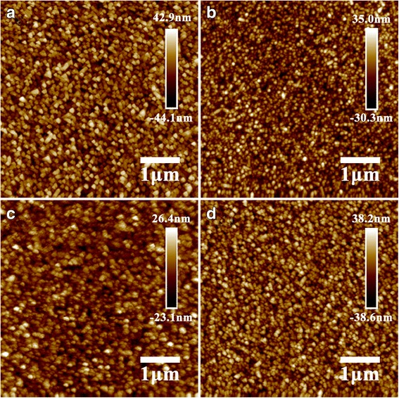
AFM images of a bare FTO, b c-TBOT, c c-TTIP, and d c-TTDB
In order to investigate the morphology and thickness of the compact layers, scanning electron microscope (SEM) measurements were performed. Additional file 1: Figure S1a–g shows the top-view and cross-sectional SEM images of different c-TiO2 layers. The compact layers prepared by different precursors reveal different surface morphology. The thickness of c-TTDB is slightly thinner (35 nm) than that of c-TTIP (50 nm) or c-TBOT (45 nm), which can be attributed to the different adhesion of precursor solutions. In addition, cyclic voltammetry (CV) is a sensitive method to detect the pinhole defects of the compact layers [20]. The CV measurements of the compact layer formed with different precursor solutions were performed, and the results were shown in Additional file 1: Figure S2. Compared with c-TTDB and c-TTIP, c-TBOT reveals fewer pinhole defects and better blocking function.
Figure 2 shows the XRD patterns of c-TiO2 deposited on the glass without FTO by multilayer coating. The c-TTDB shows a weak peak at 2θ = 25.3°, which correspond to the (101) plane of anatase phase (JCPDS card no. 21-1272). Similarly, c-TTIP exhibits an obvious anatase peak at 2θ = 25.3°. This result is consistent with the previous report in literature [21, 22]. As for c-TBOT, the diffraction peaks at 2θ = 25.3°, 37.8°, 48.0°, and 53.8° are assigned to the anatase planes of (101), (004), (200), and (105), respectively. Compared with c-TTIP and c-TTDB, c-TBOT shows the larger intensity and narrower full width at half maximum (FWHM) anatase diffraction peaks, which may be ascribed to the different thickness and crystallinity of the films [23].
Fig. 2.
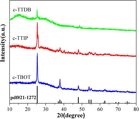
X-ray diffraction patterns of c-TBOT, c-TTIP, and c-TTDB deposited on glass without FTO
Figure 3 shows the photovoltaic parameters of the devices based on different c-TiO2 layers, including J sc, V oc, FF, and PCE, respectively. All the photovoltaic parameters were obtained from J-V curves measured under AM 1.5G and summarized in Table 1. Obviously, the photovoltaic performance is strongly influenced by compact layer. As can be observed, the devices based on c-TBOT show the largest average PCE (17.03%) than those based on c-TTDB (16.22%) and c-TTIP (16.02%). In addition, the other parameters (J sc, V oc, FF) of the cells based on c-TBOT are also larger than those based on c-TTDB and c-TTIP. This result indicates that it can improve performance by using c-TBOT as compact layer for PSCs.
Fig. 3.
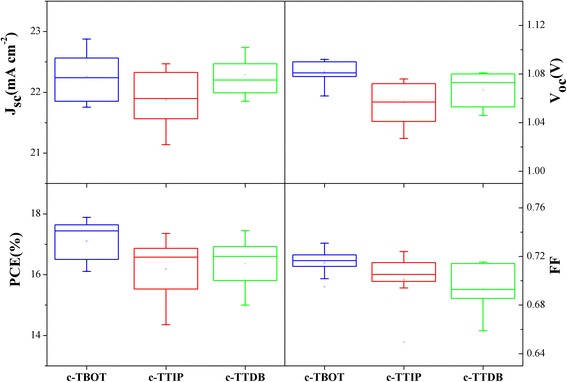
Photovoltaic parameters of devices plotted as a function of different compact layers (i.e, J sc, V oc, FF, and PCE)
Table 1.
Photovoltaic parameters of the cells with different compact layers
| Compact layer | J sc (mA/cm2) | V oc (V) | PCE (%) | PCE (max) | FF (%) |
|---|---|---|---|---|---|
| c-TBOT | 22.19 | 1.081 | 17.03 | 17.88 | 71.26 |
| c-TTIP | 21.83 | 1.054 | 16.02 | 17.32 | 69.91 |
| c-TTDB | 22.18 | 1.062 | 16.22 | 17.60 | 68.81 |
To determine the conductivity of various c-TiO2 layers, DC I-V measurements were carried out. The structure for the measurement is shown in the inset of Fig. 4a [24]. As shown in Fig. 4a, the c-TBOT reveals the best conductivity among the samples and the c-TTIP takes the second place.
Fig. 4.
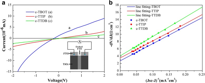
a Conductivity measurement results of various c-TiO2. The inset depicts the structure of the sample. b Plots of − dV/dJ vs (J sc-J)−1 derived from J-V curves and the linear fitting curves
The series resistance (R s) of devices fabricated with different compact layers can be calculated from the illuminated J-V curves. According to previous reports, the J-V curves of cells can be analyzed with Eq. 1 correlated to an equivalent circuit. Hence, the R s can be obtained from Eq. 2 and Fig. 4b [23, 24].
| 1 |
| 2 |
As shown in Fig. 4b, the R s of the c-TBOT device (2.71 Ω cm2) is smaller than that of c-TTIP (3.50 Ω cm2) or c-TTDB (4.08 Ω cm2), which is consistent with the resistivity measurement. A lower R s is a necessary condition for solar cells with a higher fill factor (FF) [24, 25]. The device based on c-TBOT shows the lowest R s, so it has the highest FF, which is in good agreement with the results in Table 1.
Figure 5 shows the UV-vis absorption spectra of the perovskite films based on different c-TiO2. Obviously, the absorption intensity of the sample based on c-TTDB is the largest and c-TTIP is the weakest in the range of 400–800 nm, which could be attributed to the effect of c-TiO2 layers (Additional file 1: Figure S4). Additional file 1: Figure S4 shows the transmission spectra of different c-TiO2 layers deposited on FTO glass. All the samples display good light-admitting quality in the range of 350–800 nm. Moreover, the c-TTDB and c-TBOT exhibit higher optical transmission than c-TTIP, which could be ascribed to the different properties of c-TiO2 films, such as thickness and roughness. The enhanced light transmission of the c-TiO2 certainly increases the light absorption of the perovskite film.
Fig. 5.
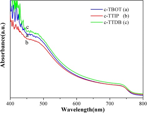
UV-vis absorption spectra of perovskite films based on different compact layers
To gain further insight into the charge transfer kinetics between perovskite and TiO2, steady-state photoluminescence (PL) and time-resolved photoluminescence (TRPL) were measured. Figure 6a shows the normalized PL spectra of FTO/c-TiO2/mp-TiO2/perovskite. All the PL spectra exhibit a photoluminescence peak at 770 nm, which is consistent with the early report in literature [9]. The intensity of the PL peaks was decreased in sequence of c-TTIP, c-TTDB, and c-TBOT. The sample of c-TBOT shows the strongest PL quenching due to the faster charge transfer [26, 27]. Meanwhile, Fig. 6b shows the TRPL spectra of FTO/c-TiO2/mp-TiO2/perovskite. The TRPL curves are fitted a biexponential decay function (Eq. 3), which include a fast decay τ 1 and a slow decay τ 2.
| 3 |
Fig. 6.
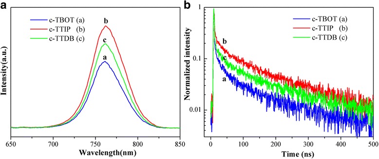
a PL and b TRPL of perovskite films based on different compact layers
The detailed parameters are summarized in Table 2. The fast decay (τ 1) could be associated with the quenching of free-carrier transfer from perovskite to electron or hole contact. While, the slow decay (τ 2) would be related to the radiative recombination of the charge carries before the charge collection [26, 27]. The perovskite films based on c-TBOT have a slow decay lifetime (τ 2) of 81.39 ns, which is shorter than those based on c-TTDB (97.30 ns) and c-TTIP (109.60 ns). This result indicates that c-TBOT has more efficient charge extraction in cells compared to c-TTDB and c-TTIP [28, 29].
Table 2.
Parameters of the TRPL spectra
| Compact layer | τ 1 (ns) | τ 2 (ns) | Fraction 1 (%) | Fraction 2 (%) |
|---|---|---|---|---|
| c-TBOT | 2.12 | 81.39 | 20.15 | 79.85 |
| c-TTIP | 3.05 | 109.60 | 9.27 | 90.73 |
| c-TTDB | 2.06 | 97.30 | 12.74 | 87.26 |
Figure 7a–c show the J-V curves of the best performing solar cells fabricated with different compact layers. All the devices based on different compact layers show varying degree of hysteresis between forward and reverse scans. It is generally recognized that the hysteresis is mainly caused by the ion migration, ferroelectric properties of perovskite material, and inadequate charge extraction at interface [30, 31]. Notably, the devices based on c-TBOT reveal a lower hysteresis than those based on c-TTIP and c-TTDB, which is attributed to the superior electron extraction ability at perovskite/TiO2 interface [31, 32].
Fig. 7.
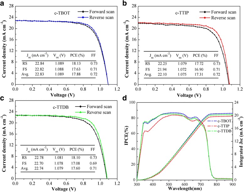
a–d Current density-voltage (J-V) curves and IPCE for the best cells based on different compact layers
Figure 7d is the incident photon-to-current conversion efficiency (IPCE) spectra of the devices based on different c-TiO2 layers. All the IPCE spectra show a broad plateau in the range of 400 to 700 nm. Meanwhile, the IPCE spectra of the devices based on c-TBOT and c-TTDB are higher than that of c-TTIP, which is attributed to the superior light absorption and efficient charge extraction [33, 34], resulting in the higher J sc. The J sc values integrated from IPCE are 20.56, 20.29, and 19.78 mA cm−2 for the devices based on c-TBOT, c-TTDB, and c-TTIP, respectively. The integrated J sc of the devices based on c-TBOT and c-TTDB are larger than that of c-TTIP, which is in good agreement with the J-V measurement.
To gain further insight into the interfacial charge transport process in PSCs, electrochemical impedance spectroscopy (EIS) measurements were carried out [34]. Figure 8 exhibits the Nyquist plots of the devices based on different c-TiO2 layers, and the inset figure depicts the equivalent circuit. According to Nyquist plots, the semicircles observed in mid-frequency region are associated with the charge transfer at the heterojunction interface in PSCs [35]. The fitted parameters for the equivalent circuit are listed in Additional file 1: Table S2. The R s value of the cells based on c-TBOT (1.907 Ω cm2) is smaller than that of c-TTIP (2.198 Ω cm2) or c-TTDB (2.201 Ω cm2), which is consistent with the results calculated from the J-V curves. While, the value of R rec based on c-TBOT (22.04 Ω cm2) is larger than that of c-TTIP (13.68 Ω cm2) or c-TTDB (18.75 Ω cm2). The larger R rec indicates a lower charge recombination, leading to larger V oc [36, 37]. This result agrees well with the J-V measurement.
Fig. 8.
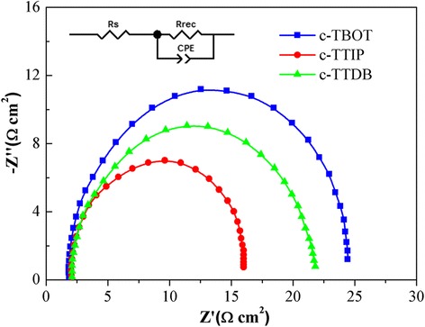
Nyquist plots of the solar cells based on different compact layers at 0.8 V under AM 1.5G. The inset is the equivalent circuit applied to fit the Nyquist plots
Conclusions
In summary, we have successfully synthesized three kinds of titanium precursor solutions with different titanium sources, i.e., c-TBOT, c-TTIP, and c-TTDB. The photovoltaic parameters of the PSCs based on c-TBOT are higher than those based on c-TTIP and c-TTDB. Additionally, DC I-V measurements show that c-TBOT has high conductivity. The UV-vis absorption spectra exhibit that c-TBOT has excellent optical properties. The PL and TRPL spectra display that the charge transfer for c-TBOT is faster than that for c-TTIP and c-TTDB. The EIS spectra reveal that the charge recombination for c-TBOT is more reduced than the others. All the results can account for the higher J sc, V oc, FF, and lower hysteresis. This study proposed a better choice to synthesize high quality compact TiO2 layer for PSCs by conventional spin-coating method.
Acknowledgements
This work is supported by the NSFC-Henan Province Joint Fund (U1604144), Program for Science and Technology Innovation Talents in Universities of Henan Province (no. 16HASTIT043), Science Fund of Henan Province (162300410020), Science Project of Education Department of Henan Province (nos. 17A140005 and 17B140001), and Science and Technology Development Project of Henan Province (nos. 172102410043 and 162102210170).
Additional file
Top-view SEM images of (a) FTO, (b) c-TBOT, (c) c-TTIP, and (d) c-TTDB. (Each sample of c-TiO2 was recoated for 5 times). Cross-sectional SEM images of (e) C-TBOT, (f) c-TTIP, and (g) c-TTDB. (Each sample of c-TiO2 was coated for 1 time). Figure S2. Cyclic voltammograms at bare FTO and that covered with different c-TiO2, scan rate 50 mV s-1, electrolyte solution 1 mM K4Fe(CN)6 + 1 mM K3Fe(CN)6 in aqueous 0.5 M KCl. Figure S3. AFM height profiles of the different c-TiO2 spin-coating on the FTO glass obtained from the 5 μm scale, (a) the underlying FTO, (b) c-TBOT, (c) c-TTIP, and (d) c-TTDB. This data can also clearly reveal the roughness of the various substrates. Figure S4. Transmission spectra of different compact films deposited on FTO glass. This data was used to analyze the transmissivity of different c-TiO2 in the range between 300 and 800 nm. Table S1. Parameters of 5 μm × 5 μm AFM roughness. Table S2. The fitted parameters for EIS equivalent circuit. (DOC 4192 kb)
Authors’ contributions
J-QQ, Z-LZ, and Y-LM carried out the laboratory experiment and drafted the manuscript. The other authors provided assistance with the experimental measurements (XRD, SEM, UV-vis, I-V, PL-TRPL, and EIS) and data analysis. All authors read and approved the final manuscript.
Competing interests
The authors declare that they have no competing interests.
Publisher’s Note
Springer Nature remains neutral with regard to jurisdictional claims in published maps and institutional affiliations.
Footnotes
Electronic supplementary material
The online version of this article (10.1186/s11671-017-2418-9) contains supplementary material, which is available to authorized users.
Contributor Information
Zhenlong Zhang, Phone: +86-371-23881602, Email: zhenlong2015@163.com.
Yanli Mao, Phone: +86-371-23881602, Email: ylmao1@163.com.
References
- 1.Kojima A, Teshima K, Shirai Y, Miyasaka T. Organometal halide perovskites as visible-light sensitizers for photovoltaic cells. J Am Chem Soc. 2009;131:6050–6051. doi: 10.1021/ja809598r. [DOI] [PubMed] [Google Scholar]
- 2.Li L, Chen YH, Liu ZH, Chen Q, Wang XD, Zhou HP. The additive coordination effect on hybrids perovskite crystallization and high-performance solar cell. Adv Mater. 2016;28:9862. doi: 10.1002/adma.201603021. [DOI] [PubMed] [Google Scholar]
- 3.Yang WS, Park BW, Jung EH, Jeon NJ, Kim YC, Lee DU, et al. Iodide management in formamidinium-lead-halide-based perovskite layers for efficient solar cells. Science. 2017;356:1376–1379. doi: 10.1126/science.aan2301. [DOI] [PubMed] [Google Scholar]
- 4.Liu M, Johnston MB, Snaith HJ. Efficient planar heterojunction perovskite solar cells by vapour deposition. Nature. 2013;501:395. doi: 10.1038/nature12509. [DOI] [PubMed] [Google Scholar]
- 5.Chen H, Liu DT, Wang YF, Wang CY, et al. Enhanced performance of planar perovskite solar cells using low-temperature solution-processed al-doped SnO2 as electron transport layers. Nanoscale Res Lett. 2017;12:238. doi: 10.1186/s11671-017-1992-1. [DOI] [PMC free article] [PubMed] [Google Scholar]
- 6.Mei AY, Li X, Liu LF, ZL K, Liu TF, Rong YG, et al. A hole-conductor-free, fully printable mesoscopic perovskite solar cell with high stability. Science. 2014;345:295–298. doi: 10.1126/science.1254763. [DOI] [PubMed] [Google Scholar]
- 7.YY D, Cai HK, Wen HB, YX W, Huang LK, Ni J, Li J, Zhang JJ. Novel combination of efficient perovskite solar cells with low temperature processed compact TiO2 layer via anodic oxidation. ACS Appl Mater Interfaces. 2016;8:12836–12842. doi: 10.1021/acsami.6b02706. [DOI] [PubMed] [Google Scholar]
- 8.Marchioro A, Teuscher J, Friedrich D, Kunst M, Van De Krol R, Moehl T, Grätzel M, Moser JE. Unravelling the mechanism of photoinduced charge transfer processes in lead iodide perovskite solar cells. Nature Photon. 2014;8:250–255. doi: 10.1038/nphoton.2013.374. [DOI] [Google Scholar]
- 9.Saliba M, Matsui T, Seo JY, Domanski K, Correa-Baena JP, Nazeeruddin MK, et al. Cesium-containing triple cation perovskite solar cells: improved stability, reproducibility and high efficiency. Energy Environ Sci. 2016;9:1989–1997. doi: 10.1039/C5EE03874J. [DOI] [PMC free article] [PubMed] [Google Scholar]
- 10.Im JH, Jang IH, Pellet N, Grätzel M, Park NG. Growth of CH3NH3PbI3 cuboids with controlled size for high-efficiency perovskite solar cells. Nature Nanotech. 2014;9:927–932. doi: 10.1038/nnano.2014.181. [DOI] [PubMed] [Google Scholar]
- 11.Giacomo FD, Zardetto V, D'Epifanio A, Pescetelli S, Matteocci F, Razza S, et al. Flexible perovskite photovoltaic modules and solar cells based on atomic layer deposited compact layers and UV-irradiated TiO2 scaffolds on plastic substrates. Adv Energy Mater. 2015;5:1–9. doi: 10.1002/aenm.201401808. [DOI] [Google Scholar]
- 12.Chen C, Cheng Y, Dai QL, Song HW. Radio frequency magnetron sputtering deposition of TiO2 thin films and their perovskite solar cell applications. Sci Rep. 2015;5:17684. doi: 10.1038/srep17684. [DOI] [PMC free article] [PubMed] [Google Scholar]
- 13.Kavan L, Tétreault N, Moehl T, Grätzel M. Electrochemical characterization of TiO2 blocking layers for dye-sensitized solar cells. J Phys Chem C. 2014;118:16408–16418. doi: 10.1021/jp4103614. [DOI] [Google Scholar]
- 14.Lee JW, Seol DJ, Cho AN, Park NG. High-efficiency perovskite solar cells based on the black polymorph of HC(NH2)2PbI3. Adv Mater. 2014;26:4991–4998. doi: 10.1002/adma.201401137. [DOI] [PubMed] [Google Scholar]
- 15.Das S, Gu G, Joshi PC, Yang B, Aytug T, Rouleau CM, Geohegan DB, Xiao K. Low thermal budget, photonic-cured compact TiO2 layers for high-efficiency perovskite solar cells. J Mater Chem A. 2016;4:9685–9690. doi: 10.1039/C6TA02105K. [DOI] [Google Scholar]
- 16.YY D, Cai HK, Ni J, Li J, HL Y, Sun XX, YX W, Wen HB, Zhang JJ. Air-processed, efficient CH3NH3PbI3-xClx perovskite solar cells with organic polymer PTB7 as a hole-transport layer. RSC Adv. 2015;5:66981–66987. doi: 10.1039/C5RA11081E. [DOI] [Google Scholar]
- 17.YG T, JH W, Zheng M, Huo JH, Zhou P, Lan Z, Lin JM, Huang ML. TiO2 quantum dots as superb compact block layers for high-performance CH3NH3PbI3 perovskite solar cells with an efficiency of 16.97. Nano. 2015;7:20539–20546. doi: 10.1039/c5nr05563f. [DOI] [PubMed] [Google Scholar]
- 18.Tan HR, Jain A, Voznyy O, Lan XZ, Pelayo García de Arquer F, Fan JZ, et al. Efficient and stable solution-processed planar perovskite solar cells via contact passivation. Science. 2017;355:722–726. doi: 10.1126/science.aai9081. [DOI] [PubMed] [Google Scholar]
- 19.Docampo P, Ball JM, Darwich M, Eperon GE, Snaith HJ. Efficient organometal trihalide perovskite planar-heterojunction solar cells on flexible polymer substrates. Nat Commun. 2013;4:2761. doi: 10.1038/ncomms3761. [DOI] [PubMed] [Google Scholar]
- 20.Kavan L, Steier L, Grätzel M. Ultrathin buffer layers of SnO2 by atomic layer deposition: perfect blocking function and thermal stability. J Phys Chem C. 2017;121:342–350. doi: 10.1021/acs.jpcc.6b09965. [DOI] [Google Scholar]
- 21.Lee CS, Kim JK, Lim JY, Kim JH. One-step process for the synthesis and deposition of anatase, two-dimensional, disk-shaped TiO2 for dye-sensitized solar cells. ACS Appl Mater Interfaces. 2014;6:20842–20850. doi: 10.1021/am505217k. [DOI] [PubMed] [Google Scholar]
- 22.Roose B, Gödel KC, Pathak S, Sadhanala A, Baena JPC, Wilts BD, et al. Enhanced efficiency and stability of perovskite solar cells through Nd-doping of mesostructured TiO2. Adv Energy Mater. 2016;6:1501868. doi: 10.1002/aenm.201501868. [DOI] [Google Scholar]
- 23.Wang YF, Wu J, Zhang P, Liu DT, Zhang T, Ji L, et al. Stitching triple cation perovskite by a mixed anti-solvent process for high performance perovskite solar cells. Nano Energy. 2017;39:616–625. doi: 10.1016/j.nanoen.2017.07.046. [DOI] [Google Scholar]
- 24.Zhang HY, Shi JJ, Xu X, Zhu LF, Luo YH, Li DM, Meng QB. Mg-doped TiO2 boosts the efficiency of planar perovskite solar cells to exceed 19. J Mater Chem A. 2016;4:15383–15389. doi: 10.1039/C6TA06879K. [DOI] [Google Scholar]
- 25.Chen BX, Rao HS, Li WG, YF X, Chen HY, Kuang DB, Achieving SCY. High-performance planar perovskite solar cell with Nb-doped TiO2 compact layer by enhanced electron injection and efficient charge extraction. J Mater Chem A. 2016;4:5647–5653. doi: 10.1039/C6TA00989A. [DOI] [Google Scholar]
- 26.Liang PW, Liao CY, Chueh CC, Zuo F, Williams ST, Xin XK, Lin JJ, Jen JK. Additive enhanced crystallization of solution-processed perovskite for highly efficient planar-heterojunction solar cells. Adv Mater. 2014;26:3748–3754. doi: 10.1002/adma.201400231. [DOI] [PubMed] [Google Scholar]
- 27.Yeo JS, Kang R, Lee S, Jeona YJ, Myoung NS, Lee CL, et al. Highly efficient and stable planar perovskite solar cells with reduced graphene oxide nanosheets as electrode interlayer. Nano Energy. 2015;12:96–104. doi: 10.1016/j.nanoen.2014.12.022. [DOI] [Google Scholar]
- 28.Choi J, Song S, Hörantner MT, Snaith HJ, Park T. Well-defined nanostructured, single-crystalline TiO2 electron transport layer for efficient planar perovskite solar cells. ACS Nano. 2016;10:6029–6036. doi: 10.1021/acsnano.6b01575. [DOI] [PubMed] [Google Scholar]
- 29.Zhang P, Wu J, Wang YF, Sarvari H, Liu DT, et al. Enhanced efficiency and environmental stability of planar perovskite solar cells by suppressing photocatalytic decomposition. J Mater Chem A. 2017;5:17368–17378. doi: 10.1039/C7TA04014H. [DOI] [Google Scholar]
- 30.Frost JM, Butler KT, Brivio F, Hendon CH, Van Schilfgaarde M, Walsh A. Atomistic origins of high-performance in hybrid halide perovskite solar cells. Nano Lett. 2014;14:2584–2590. doi: 10.1021/nl500390f. [DOI] [PMC free article] [PubMed] [Google Scholar]
- 31.Wu B, KW F, Yantara N, Xing GC, Sun SY, Sum TC, Mathews N. Charge accumulation and hysteresis in perovskite-based solar cells: an electro-optical analysis. Adv Energy Mater. 2015;5:1500829. doi: 10.1002/aenm.201500829. [DOI] [Google Scholar]
- 32.Lee YH, Luo JS, Son MK, Gao P, Cho KT, Seo JY, et al. Enhanced charge collection with passivation layers in perovskite solar cell. Adv Mater. 2016;28:3966–3972. doi: 10.1002/adma.201505140. [DOI] [PubMed] [Google Scholar]
- 33.Kim HS, Lee JW, Yantara N, Boix PP, Kulkarni SA, Mhaisalkar S, Grätzel M, Park NG. High efficiency solid-state sensitized solar cell-based on submicrometer rutile TiO2 nanorod and CH3NH3PbI3 perovskite sensitizer. Nano Lett. 2013;13:2412–2417. doi: 10.1021/nl400286w. [DOI] [PubMed] [Google Scholar]
- 34.Li JF, Zhang ZL, Gao HP, Zhang Y, Mao YL. Effect of solvents on the growth of TiO2 nanorods and their perovskite solar cells. J Mater Chem A. 2015;3:19476–19482. doi: 10.1039/C5TA03765D. [DOI] [Google Scholar]
- 35.Xu X, Zhang HY, Shi JJ, Dong J, Luo YH, Li DM, Meng QB. Highly efficient planar perovskite solar cells with a TiO2/ZnO electron transport bilayer. J Mater Chem A. 2015;3:19288–19293. doi: 10.1039/C5TA04239A. [DOI] [Google Scholar]
- 36.Li Y, Zhu J, Huang Y, Wei JF, Liu F, Shao ZP, et al. Efficient inorganic solid solar cells composed of perovskite and PbS quantum dots. Nano. 2015;7:9902–9907. doi: 10.1039/c5nr00420a. [DOI] [PubMed] [Google Scholar]
- 37.Gu XL, Wang YF, Zhang T, Liu DT, Zhang R, Zhang P, et al. Enhanced electronic transport in Fe3+-doped TiO2 for high efficiency perovskite solar cells. J Mater Chem C. 2017;5:10754–10760. doi: 10.1039/C7TC03845C. [DOI] [Google Scholar]


