Abstract
Automated three-dimensional retinal fluid (named symptomatic exudate-associated derangements, SEAD) segmentation in 3D OCT volumes is of high interest in the improved management of neovascular Age Related Macular Degeneration (AMD). SEAD segmentation plays an important role in the treatment of neovascular AMD, but accurate segmentation is challenging because of the large diversity of SEAD size, location, and shape. Here a novel voxel classification based approach using a layer-dependent stratified sampling strategy was developed to address the class imbalance problem in SEAD detection. The method was validated on a set of 30 longitudinal 3D OCT scans from 10 patients who underwent anti-VEGF treatment. Two retinal specialists manually delineated all intraretinal and subretinal fluid. Leave-one-patient-out evaluation resulted in a true positive rate and true negative rate of 96% and 0.16% respectively. This method showed promise for image guided therapy of neovascular AMD treatment.
Index Terms: Age-related macular degeneration, class imbalance, intraretinal fluid, stratified sampling, subretinal fluid
I. Introduction
Since first described in 1991, optical coherence tomography has become an increasingly important imaging technique, especially for the non-invasive imaging of human retina [1], [2]. OCT allows to image the inside of the eye with microscopic resolution, enabling clinicians better understanding of eye and especially retinal diseases [3]–[8].
Neovascular or exudative age-related macular degeneration (AMD) is an advance form of AMD and the most important cause of blindness in the developed world. Neovascular AMD or choroidal neovascularization (CNV) is characterized by the growth of abnormal blood vessels from choroid into the retina, and associated leaking of fluid. The fluid leads to vision loss and ultimate destruction of the normal architecture of the retina. Anti-Vascular Endothelial Growth Factor (Anti-VEGF) based drugs have been proven to be highly effective treatment of CNV and require precise quantification of the distribution, size, and number of fluid pockets [9]–[11].
Several research groups have previously addressed detection, segmentation, and quantification of intraretinal and subretinal fluid regions in OCT images using semi-automatic or fully automatic methods. In 2005, Fernandez et al. proposed a method to delineate the intraretinal and subretinal fluid regions in 2D OCT B-scans using a deformable model. This semi-automatic method requires human interaction in the initialization of the snake [10]. Wikins et al. proposed a fully automatic method to segment intraretinal systoid fluid in systoid macular edema in individual 2D B-scan. Intraretinal fluids are segmented by a combination of thresholding and boundary tracing [12]. Zheng et al. proposed a semi-automatic approach to segment intraretinal and subretinal fluid in individual 2D OCT B-scans [13]. A four step procedure, including a coarse segmentation and a fine segmentation step, is applied to generate target region candidates. Then an expert clicks on each of the desired candidate and quantitative analysis can be done afterwards. Chen et al. proposed a fully automatic and true 3D method for segmentation of fluid-associated abnormalities in 2012 [11]. A combined graph-search/graph-cut method was developed to simultaneously segment the upper retinal surface, lower retinal surface, and one or more fluid-filled regions between the two layers.
The above approach [11] yields good segmentation for large, well-defined fluid pockets. However, it is substantially less sensitive to smaller fluid regions, whose boundaries are more ambiguous and locations are more unpredictable. It also suffers from detecting sub-RPE deposits or bright drusen as false positives. As reported in their paper, these problems were hard to fix as it depends largely on the graph construction. However, increasing sensitivity and specificity is quite important for real clinical data, but challenging because patients vary greatly in disease severity.
We formulate the detection of SEADs in OCT scans as a class imbalance problem, meaning one of the classes is represented by a small number of cases compared to the other classes [14]. High imbalance occur in applications where the classifier is to detect a rare but important case (SEADs in our application). Class imbalance can produce a substantial deterioration of the performance achieved by existing learning and classification system [14], [15]. In the context of SEAD detections, the problem is further complicated by the fact that SEADs show some layer-dependent properties, which means SEADs are more likely to appear in some layers and less likely in other retinal layers.
In this manuscript, we propose a classification method that utilizes the prior information of the layer-dependency of SEADs by employing a stratified sampling technique in order to improve the detection sensitivity for real clinical OCT data. Stratified sampling has been applied in many areas and achieved good results, including remote sensing studies [16], [17] and data analysis in large phytosociological databases [18] to deal with class imbalance problem and has achieved good results. Our method was validated on a set of longitudinal clinical data from neovascular AMD patients with varying disease stages.
II. Experimental Methods
In this study, a set of 30 SD-OCT volumes from 10 subjects who underwent anti-vascular endothelial growth factor (anti-VEGF) treatment were analyzed. These patients underwent an initial 12 week standard anti-VEGF treatment and then continued for a patient-specific treatment for a period of 12 months. SD-OCT scans were taken at week 0, 2, 4, 6, 8, 10, and 12 for the first standard 12-week treatment, and two more scans during the patient-specific treatment period.
Two fellowship-trained retinal specialists individually detected and segmented all intraretinal and subretinal fluid regions in the original image slices using truthmarker, an iPad application [19]. Due to the time-consuming property of the job, only the baseline scan (week 0, first scan), 2-month follow-up scan (week 8, middle scan), and 12-month follow-up scan (last scan) were used for this study. Informed consent for research use of data was sought and obtained from each study participant before participation. The study protocol was approved by the institutional review board of the University of Iowa and conformed to the tenets of the Declaration of Helsinki.
A Topcon 3D Swept source OCT (Topcon Inc., Paramus, NJ), with a central wavelength of 1050 nm, was used to acquire the scans. The scanning range is 6 mm × 6 mm × 2.3 mm centered on the fovea, with a field angle of 45°. The volume size is 512 × 128 × 885 voxels with a physical voxel size of 11.7 μm × 46.9 μm × 2.7 μm. The original intensity value was 16 bits and has been normalized to [0, 1].
III. Methods
In this section, the proposed method is described in detail. First, a pre-processing step is necessary to enhance the signal-to-noise ratio, followed by an 11-layer segmentation. Then, a voxel classification is applied and various three-dimensional features, including textural, structural, and locational information, are extracted. Although the shape, size, and location of fluid regions are quite unpredictable, we noticed some layer-dependent properties of the fluid regions and a layer-dependent sampling model was applied.
Preprocessing includes a recursive anisotropic diffusion filter plus brightness curve transform in order to reduce noise and enhance the abnormality regions.
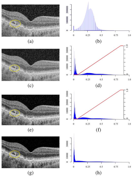
Noise is an inherent problem in coherent imaging techniques, such as ultrasound and OCT. The main noise source is speckle noise, which is caused by random interference of waves reflected from sub-resolution variance within the tissue. Consequently, with a longer wavelength, more speckle noise is expected. Speckle noise is hard to eliminate because it is signal-dependent. In the past decades, many denosing techniques have been developed [10], [20], [21]. We adapt a non-linear three-dimensional anisotropic diffusion filter to enhance the signal-to-noise ratio [22]. Fig. 1(a) and (c) show a typical B-scan before and after denoising using the anisotropic diffusion filter.
Fig. 1.
Image quality enhancement. The left column shows a single B-scan of the volume from the same subject. The right column shows the intensity histogram of the entire volume. Note in (d), (f), and (h), the high peak at intensity 0 is clipped so that the rest of the histogram can be better viewed. (a) Single B-scan of raw, unpreprocessed volume. A Perona and Malik conductance function is applied and the gradient magnitude threshold is 2.0 [23]. (b) Histogram of the raw volume. The regular peak is caused by the scanner hardware. (c) The same B-scan after an anisotropic diffusion filter. (d) Histogram of (c). The red line is the brightness transform curve (axis on the right side) applied on this histogram. (e) The same B-scan after a brightness curve transform and a followed anisotropic diffusion filter. (f) Histogram of (e). The red line is the brightness transform curve (axis on the right side) applied on this histogram. (g) The same B-scan after a second brightness curve transform and a followed anisotropic diffusion filter. In this final figure, the speckle noise has been suppressed while the texture information of the layers and SEADs has been preserved. (h) Histogram of (g). The final histogram doesn’t show a bimodal distribution, meaning the lower distribution, most of which are noise pixels, has been removed.
Fig. 1(c) shows the noise is suppressed after the anisotropic diffusion filter. However, the layer as well as the fluid-filled regions (circled in yellow) are also blurred. This introduces difficulties to later detection and segmentation. Fig. 1(d) shows the corresponding histogram of Fig. 1(c). Note the high peak value at intensity 0, which can go as high as 22 million, is not shown so that the rest of the histogram can be shown in better scale. The histogram shows a double-peaked bimodal distribution. One centers at around the intensity of 0.04 and shows a steep shape, while the other centers at around the intensity of 0.3 and shows a flat shape. The histogram drops to near 0 when the intensity is larger than 0.91. A further examination shows that most pixels in the left distribution are noise pixels (Fig. 2). Very little structural information is found in this area. Hence, a non-linear brightness curve transform is applied to further suppress image noise. The red line in Fig. 1(d) is the transformation curve and Fig. 1(e) shows the image after brightness curve transform followed by another anisotropic diffusion filter. Fig. 1(f) is the corresponding image histogram. This histogram again shows a bimodal distribution. Hence, another brightness curve transform followed by an anisotropic diffusion filter is applied. The final image and histogram is given in Fig. 1(g) and (h). In the final histogram, the bimodal distribution begins to merge with most of the noise pixels been removed.
Fig. 2.
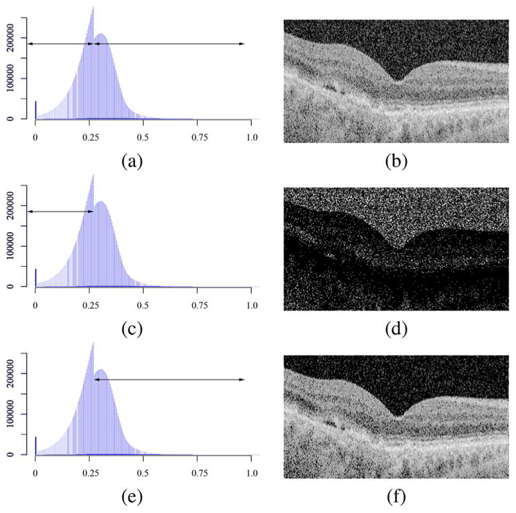
An examination of the histogram. The lower part of the histogram is mainly composed of noise while the retinal layer information is inside the higher part of the histogram. The gray level of B-scans were adjusted for better visualization. (a) and (b): Single B-scan from the raw OCT volume and the histogram of the raw OCT volume. (c) Histogram of the total raw OCT volume, in which the lower part of the histogram is indicated with arrow. (d) The same B-scan as in (b), in which only pixels that fall in the lower part of the histogram are shown. (e) Histogram of the total raw OCT volume, in which the higher part of the histogram is indicated with arrow. (f) The same B-scan as in (b), in which only pixels that fall in the higher part of the histogram are shown.
After the sequence of brightness curve transform and anisotropic diffusion filter, most of the image noise with lower gray value was suppressed while the structural information is preserved. Most importantly, the desired fluid-filled regions are further distinguished from retinal layers, as shown in Fig. 1(h). A Perona-Malik anisotropic diffusion filter was used, with an iteration of 15 and time step of 0.06.
A. Layer Segmentation
Our group has previously reported a simultaneous 11-layer segmentation algorithm based on graph methods [24], [25]. The retinal surfaces with more obvious features are first detected in a downsampled low-resolution image volume. The other surfaces are refined in full-scale subvolumes constrained by the surfaces detected in the first stage. In other words, the eleven surfaces are hierarchically detected starting from the most easily detectable ones and ending with the most subtle interfaces. Once all surfaces are detected, a thin plate spline is applied to smooth the surfaces (Fig. 3).
Fig. 3.
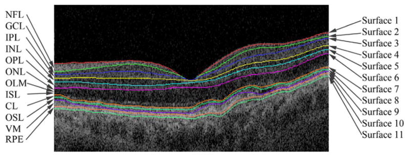
An example of eleven-layer segmentation. The level scale and orientation of the B-scan was adjusted when the layers were overlapped on the B-scan.
Fluid-associated abnormalities also exhibit some layer-dependent properties (Fig. 4). For example, intraretinal fluid normally appears above the outer plexiform layer (OPL, L6), which shows large, ovoid areas of low reflectivity, separated by high reflective septa that represent intraretinal cystoid-like cavities [26]. Subretinal fluid is a dark accumulation of fluid beneath the outer segment layer (OS, L7). The highly reflective band created by the RPE differentiates sub-RPE fluid (below) from subretinal fluid (above). Hence, these layers have a higher likelihood of fluid-associated abnormalities. On the other hand, although the outer nuclear layer (ONL) is not a likely region for fluid, because of its reduced intraretinal reflectivity, it exhibits a similar texture as fluid-associated abnormalities, thus leading to false positives. This is also regarded as a layer-dependent property.
Fig. 4.
Examples of intraretinal fluid and subretinal fluid. (a) Intraretinal fluid. It norally appears above OPL. (b) Subretinal fluid. It is normally dark accumulations of fluid beneath OSL. It is also shown that ONL has a very similar texture to fluid-associated abnormalities.
B. Voxel Classification With Stratified Sampling
Based on the previous observations, we propose a supervised voxel classification method based on a stratified sampling technique. A stratified sample is constructed by classifying the whole sample region in sub-regions (or strata), based on some foregone characteristics of the regions [27]. The strata should be mutually exclusive and collectively exhaustive, meaning every sample point in the sample region must be assigned to one and only to one stratum. Hence, by manipulating the sampling ratio differently within each strata, we expect to simultaneously increase sensitivity in regions likely to have SEADs and increase specificity in regions prone to false positives.
1) Training Phase
During the training phase, for each sample point, a set of features, including textural, structural, and positional information, is calculated (listed in Table I) [11]. The sampling strategy is given in Table II. The whole sample region between NFL and RPE was stratified into three strata: NFL-OPL, ONL-OSL, and VM-RPE. The ONL-OSL region was undersampled to deal with the difficulties of segmenting SEADs reliably without increasing false positives in this specific region, whereas NFL-OPL and VM-RPE were relatively oversampled to increase sensitivity to SEADs. In doing this, first of all, a total number of 40 000 negative sample points were assigned to these three strata proportionately to the approximate average total volume of each stratum. Then a total number of 2 000 positive sample points were empirically assigned to each stratum to oversample NFL-OPL and VM-RPE but undersample ONL-OSL. Within each stratum, simple random sampling was applied.
TABLE I.
A List of Selected Features
| Feature Index | Description |
|---|---|
| 1–5 | First eigenvalues of the Hessian matrices at scales σ=1, 3, 6, 9, and 14. |
| 6–10 | Second eigenvalues of the Hessian matrices at scales σ=1, 3, 6, 9, and 14. |
| 11–15 | Third eigenvalues of the Hessian matrices at scales σ=1, 3, 6, 9, and 14. |
| 16–45 | Gaussian filter banks of zero, first, and second orders with derivatives at scales σ=2, 4, and 8. |
| 46–48 | Distances to surfaces 1, 7, and 11. |
| 49–52 | Texture information, including mean intensity, co-occurrence matrix entropy and inertia, and wavelet analysis standard deviation. |
TABLE II.
The Distribution of Positive Sample Points (Sp) and Negative Sample Points (Sn)
| Stratum | Sp | Sn | Sp : Sn |
|---|---|---|---|
| NFL-OPL | 1,200 | 12,000 | 1:10 |
| ONL-OSL | 400 | 24,000 | 1:60 |
| VM-RPE | 400 | 4,000 | 1:10 |
| Total | 2,000 | 40,000 | 1:20 |
2) Testing Phase
During the testing phase, the same set of features is extracted for each voxel inside retina layers. A k-nearest-neighbor classifier [28](k = 21) was chosen based on its performance in comparative preliminary experiments on a small, independent set of images performed in the earlier experiments [11]. For each test voxel, the average label of the k nearest neighbors were assigned as a final probability of this voxel being a SEAD, assigning each voxel a probability between 0 and 1, which was rescaled to [0, 255] in the output image. A leave-one-patient-out evaluation strategy was used.
IV. Results
Fig. 5 shows a comparison of typical segmentation result overlapped with manual segmentation. The proposed method was able to detect SEADs with small sizes and control false positives at the same time.
Fig. 5.
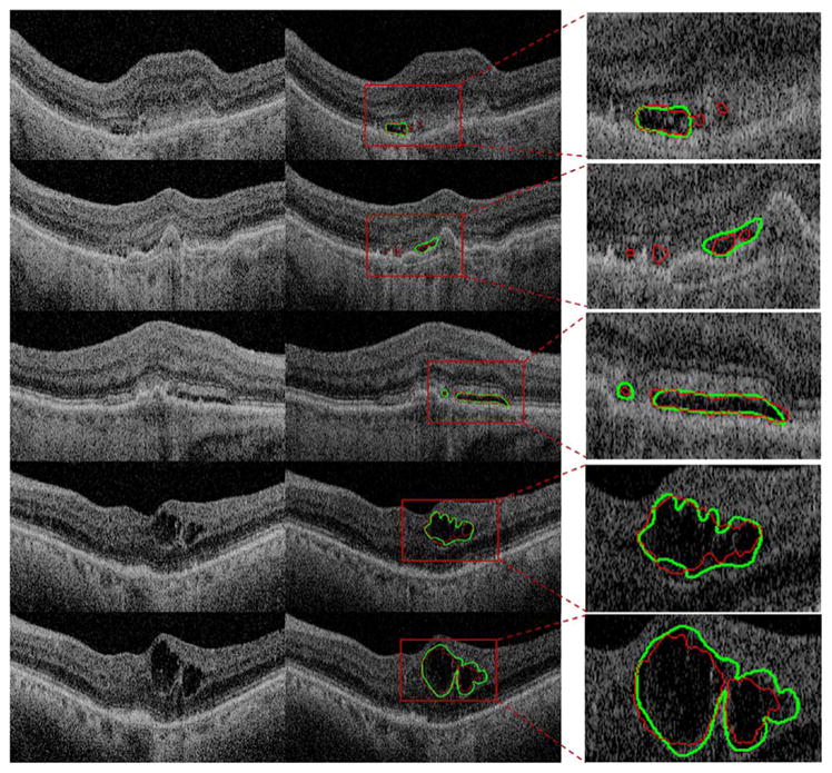
Example of typical results. Left column: original B-scan. Middle column: segmentation result. The green line is the segmentation by the human expert. The red line is the segmentation by the automatic method. Right column: inset view of SEAD segmentation.
The performance of the stratified sampling method and the simple sampling method [11] were compared to the performance of expert 1 (E1) and expert 2 (E2). The average true volume (Vt), true positive volume (Vtp), false negative volume (Vfn), and false positive volume (Vfp) of E1 and E2 are reported in Tables III and IV. Vf and Va are defined as the total SEAD volume segmented by human expert and automatic method, respectively. Vtp is defined as the subset of Vt that was detected by automatic method (Vt ∩ Va).Vfn (false negative, i.e., the volume only detected by human experts) is defined as the subset of Vt that was not detected by automatic method (Vt − Vt ∩ Va).Vfp (false positive, i.e., the volume only detected by automatic systems) is defined as Vfp = {V | (V ⊂ Va) ∩ (V ⊄ Vt)}. For the sake of easy reading, the results from the same subject were added and shown in the same row. True positive rate (TPR) indicates the fraction of correctly detected volume in the reference standard delineation; false positive rate (FPR) denotes the fraction of incorrectly detected volume in true negative volume. The definitions are given as follows and more details can be found in [29].
TABLE III.
The Average Value of Vt, Vtp, Vfn, and Vfp in mm3, Using Simple Sampling. TPR and FPR are in %
| Subject Index | Vt | Vtp | Vfn | Vfp | TPR1 | FPR1 |
|---|---|---|---|---|---|---|
| Subject 1 | 0.094 | 0.086 | 0.007 | 0.014 | 92.736 | 0.160 |
| Subject 2 | 1.731 | 1.726 | 0.005 | 0.047 | 99.705 | 0.634 |
| Subject 3 | 0.087 | 0.086 | 0.001 | 0.010 | 99.129 | 0.138 |
| Subject 4 | 0.071 | 0.070 | 0.001 | 0.010 | 98.710 | 0.127 |
| Subject 5 | 0.541 | 0.540 | 0.001 | 0.001 | 99.815 | 0.015 |
| Subject 6 | 1.411 | 1.401 | 0.011 | 0.004 | 99.257 | 0.035 |
| Subject 7 | 0.411 | 0.398 | 0.012 | 0.015 | 97.364 | 0.219 |
| Subject 8 | 0.043 | 0.038 | 0.005 | 0.019 | 89.843 | 0.265 |
| Subject 9 | 0.529 | 0.525 | 0.004 | 0.016 | 99.262 | 0.221 |
| Subject 10 | 0.174 | 0.173 | 0.001 | 0.022 | 99.216 | 0.322 |
| Average | - | - | - | - | 97.504 | 0.214 |
| Std | - | - | - | - | 3.413 | 0.176 |
| SEM | - | - | - | - | 1.079 | 0.056 |
TABLE IV.
The Average Value of Vt, Vtp, Vfn, and Vfp in mm3, Using Stratified Sampling. TPR and FPR are in %
| Subject Index | Vt | Vtp | Vfn | Vfp | TPR2 | FPR2 |
|---|---|---|---|---|---|---|
| Subject 1 | 0.094 | 0.079 | 0.014 | 0.006 | 84.848 | 0.072 |
| Subject 2 | 1.731 | 1.719 | 0.014 | 0.044 | 99.296 | 0.599 |
| Subject 3 | 0.087 | 0.082 | 0.005 | 0.003 | 93.958 | 0.041 |
| Subject 4 | 0.071 | 0.065 | 0.006 | 0.004 | 90.906 | 0.051 |
| Subject 5 | 0.541 | 0.537 | 0.004 | 0.001 | 99.219 | 0.010 |
| Subject 6 | 1.411 | 1.403 | 0.004 | 0.010 | 99.433 | 0.078 |
| Subject 7 | 0.411 | 0.396 | 0.015 | 0.008 | 96.776 | 0.121 |
| Subject 8 | 0.043 | 0.042 | 0.000 | 0.021 | 97.964 | 0.286 |
| Subject 9 | 0.529 | 0.525 | 0.004 | 0.020 | 99.298 | 0.269 |
| Subject 10 | 0.174 | 0.173 | 0.001 | 0.003 | 99.221 | 0.041 |
| Average | - | - | - | - | 96.092 | 0.157 |
| Std | - | - | - | - | 4.886 | 0.182 |
| SEM | - | - | - | - | 1.539 | 0.058 |
| (1) |
| (2) |
where Ud is the whole scene domain and in the present case the volume between NFL and RPE. Tables III and IV show that compared with TPR1, TPR2 decreased slightly (with a p-value of 0.182 in the paired t-test; the Shapiro-Wilk normality test confirmed at a significance level of 0.05.), whereas compared with FPR1, FPR2 showed a significant improvement (with a p-value of 0.049 in the paired t-test; the Shapiro-Wilk normality test confirmed at a significance level of 0.05.). To calculate Tables III and IV, the values of Vt, Vtp, Vfn, and Vfp were first calculated for E1 and E2 separately and then averaged. The values were rounded during each step of the calculation.
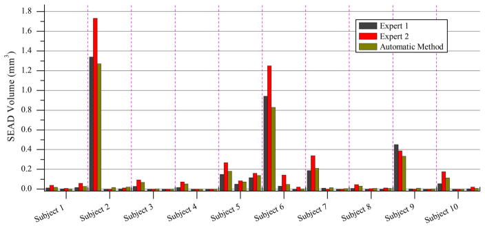
A comparison between the performance of E1, E2, and the automatic method is given in Fig. 6. The inset windows shows that the performance generally decreased when SEAD volume were small. The automatic method correlated better with the average volume of E1 and E2 (Fig. 6(c)). Expert 2 gave a consistently larger SEAD volume compared with E1 (Fig. 6(d)). Fig. 7 shows the segmented SEAD volume of all subjects by three different methods (i.e., E1, E2, and automatic method).
Fig. 6.
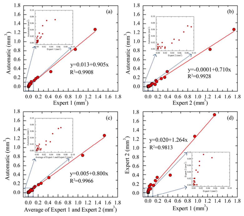
Inter-grader assessment. (a) The scatter plot of SEAD volume between the automatic method and E1, and the corresponding R-squared value. (b) The scatter plot of SEAD volume between the automatic method and E2, and the corresponding R-squared value. (c) The scatter plot of SEAD volume between the automatic method and the average of E1 and E2, and the corresponding R-squared value. (d) The scatter plot of SEAD volume between E1 and E2, and the corresponding R-squared value.
Fig. 7.
Bar plot of SEAD volume (ten subjects, each with three OCT scans).
The ROC curve is given in Fig. 8, which was created by thresholding the output gray-scale image and calculating the sensitivity and specificity at different thresholding levels. The area under the curve (AUC) was 0.92 for our method with respect to E1 and 0.80 with respect to E2. Fig. 9 shows the Bland-Altman plot of SEAD volume per scan. The x-axis is the average SEAD volume of the manual segmentation and the automatic segmentation, while the y-axis is the difference in SEAD volume between the manual segmentation and the automatic segmentation. Fig. 9(a) shows the automatic method gave a larger measurements than E1 for median SEADs, but it gave a smaller measurements for large SEADs. Fig. 9(b) shows the automatic method gave a consistently smaller measurements than E2. This is consistent with the information we observed in Fig. 6.
Fig. 8.
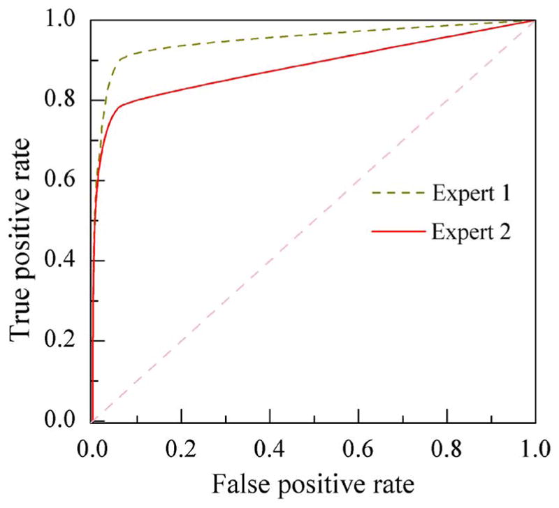
ROC of the stratified sampling algorithm for detected SEAD volume. The green line is the ROC with respect to E1 and the red line is with respect to E2.
Fig. 9.
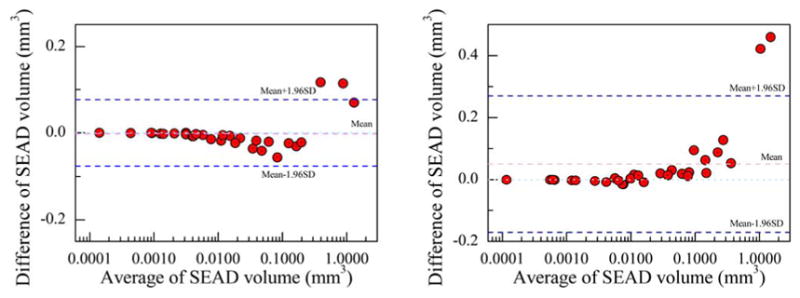
Bland-Altman plot of SEAD volume per scan. The x-axis is shown in logarithm scale. (a) Bland-Altman plot for E1. (b) Bland-Altman plot for E2.
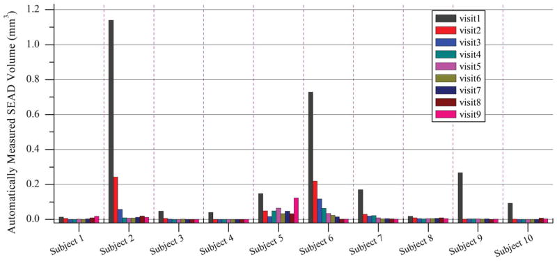
The longitudinal analysis for all 10 subjects is given in Fig. 10. Each subject underwent an initial 12-week standard anti-VEGF treatment and then continued for a patient-specific treatment for a period of 12 months. During the whole period, nine visits for SD-OCT scans were taken at week 0, 2, 4, 6, 8, 10, and 12 for the standard 12-week treatment and two more scans during the patient-specific treatment period. Most patient showed a consistent decrease in SEAD volume with anti-VEGF treatment. However, a few subjects showed different behavior under anti-VEGF treatment. For example, subject 5 showed a relatively consistent volume size over the 9 visits, meaning a failure in anti-VEGF treatment.
Fig. 10.
Longitudinal analysis of 10 subjects, each with 9 OCT scans from 9 visit taken at week 0, 2, 4, 6, 8, 10, 12 for the first standard 12-week treatment and two more scans during the patient specific treatment period. With anti-VEGF treatment, most of the patients showed a consistent decrease in SEAD volume. However, there are a few exceptions. For example, subject 5 showed a relatively stable SEAD volume over the 9 visits.
V. Discussion
Attempting to simultaneously segment SEADs at different scales, i.e., different sizes, from clinical datasets is a challenging problem due to the variation of SEAD size, shape, and location of SEADs, and the similarity between the foreground and background textures. When a human interprets a scene, he or she generally involves the assessment of high-level contextual features [30]. But point-wise queries, as in a supervised classification method, do not exploit full interpreter knowledge of the spatial context in all different scales. The combination of locational prior information is an attempt to make the machine-based classification better resembles human perception.
For the SEADs that have been detected, the scatter plot of the per-SEAD-volume is given in Fig. 11. The red points shows the per-SEAD-volume for E1 and the green points for E2. In this figure, E2 showed a larger per-SEAD volume, which may be one reason why E2 showed a consistently larger SEAD volume per scan as shown in Figs. 6 and 9. On the other hand, E1 and the automatic method showed a relatively better agreement on per-SEAD-volume. Logarithm scale was chosen so that the SEADs with smaller volumes are shown better.
Fig. 11.
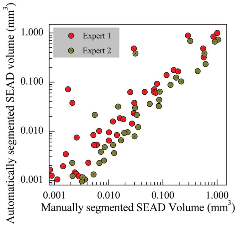
Scatter plot of per SEAD volume.
The average distances between SEADs to fovea center and between SEADs to Bruch’s Membrane were also measured (Figs. 12 and 13). The location of the fovea center was automatically detected as the A-scan location with the minimum distance between the first and fourth surfaces and results were manually checked for correctness. Compared with the average distance to Bruch’s Membrane, the distance to fovea center showed more consistency. However, the distance to fovea center is given as a distance in a 3D volume (distance to a point in 3D), while the distance to Bruch’s Membrane is a distance in 2D (distance to a 2D plane). Hence, Fig. 13 has a smaller scale than Fig. 12 and the error is also exaggerated. In Fig. 13, a few points showed a negative distance to Bruch’s Membrane because the average location of SEADs was beneath the average level of Bruch’s Membrane. A density plot is used to show overlapped points.
Fig. 12.

Scatter plot of average distance to fovea center.
Fig. 13.
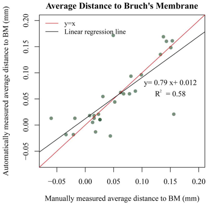
Scatter plot of average distance to Bruch’s Membrane.
The total number of small (<0.01 mm3), median (>0.01 mm3 and <0.1 mm3), and large (>0.1 mm3) SEADs in all test OCT volumes is given in Fig. 14. As expected, in the small SEAD group, the number of automatically detected SEADs is significantly larger than manually segmented SEADs, while in the other two groups, the number is almost even. It is consistent with our expectation because false positives are mainly small regions and fall in the small SEADs group.
Fig. 14.
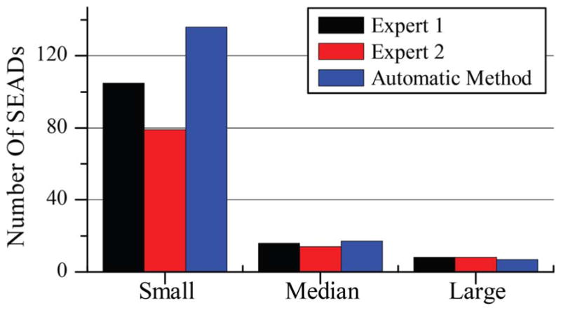
Number of SEADs categorized into small (<0.01 mm3), median (>0.01 mm3 and <0.1 mm3), and large (>0.1 mm3).
A. Limitations
There are several alternative venues for further improving the proposed method. The current method depends on the layer segmentation results. If the layer segmentation is incorrect, it will affect the sampling ratio and may cause classification errors. Besides, the final SEAD segmentation is achieved by a simple thresholding of the gray value classification result, which gives no guarantee as to the smoothness of the SEAD boundary. As can be imagined, the lack of a smooth boundary causes problem in accurate SEAD delineation, but does not have a significant impact on volume. Because of the same reason (simple thresholding), many small false positives were left in the image and the number of SEAD was not a reliable parameter in comparison to the human expert, especially for smaller SEADs. One method to alleviate the above problems was to apply adaptive thresholding.
In this study, the method was only validated on three time-points (out of a total nine timepoints) for all the 10 patients. The reason is that manual tracing of all intraretinal and subretinal fluid regions required expert knowledge and is tedious and time-consuming. With the facilitation of the tablet-based software, tracing all fluid regions and later review of the segmentation result takes around 120 minutes for each OCT volume.
Even though the method has achieved good results, the distribution of sample points is mainly based on empirical analysis. In the future, we plan to design a more systematic stratification method.
VI. Conclusion
We reported a fluid-associated abnormality detection and segmentation method in this manuscript. Detection and segmentation of fluid-associated abnormalities in clinical data is a challenging problem in several aspects. Patients might have different severity of disease, which makes the size, location, and shape of fluid regions unpredictable. Moreover, simultaneously improving true positives and controlling false positives is clinically important. We introduced a layer-dependent stratified sampling strategy to solve the problem. Results showed this method was able to achieve very high TPR (96%) and maintain the value of FPR to a very low level (0.16%).
Though our approach still has some weaknesses, including the lack of smoothness in region boundary, it has shown good performance if tested on clinical data. Automated segmentation of subretinal and intraretinal fluid in neovascular AMD is going to be crucial in improved image-guided therapy, and thereby improve outcomes in this potentially blinding disease.
Acknowledgments
This material is based upon work supported in part by the National Institutes of Health grants R01 EY018853, R01 EY019112, R01 EY017451, R01 EY016822, and R01 EB004640; the Department of Veterans Affairs, Veterans Health Administration, Office of Research and Development Grant I01 CX000119; Research to Prevent Blindness, New York, NY. X. Xu was also supported by the National Natural Science Foundation of China (81401480).
Contributor Information
Xiayu Xu, Department of Life Science and Technology, Xi’an Jiaotong University, Xi’an 710049, China. She was with the Department of Electrical and Computer Engineering, University of Iowa, Iowa City, IA 52242 USA.
Kyungmoo Lee, Department of Electrical and Computer Engineering, University of Iowa, Iowa City, IA 52242 USA.
Li Zhang, Department of Electrical and Computer Engineering, University of Iowa, Iowa City, IA 52242 USA.
Milan Sonka, Department of Electrical and Computer Engineering, the Department of Ophthalmology and Visual Sciences, and the Department of Radiation Oncology, the University of Iowa, Iowa City, IA 52242 USA.
Michael D. Abràmoff, Department of Ophthalmology and Visual Sciences, the Department of Electrical and Computer Engineering, the Department of Biomedical Engineering, the University of Iowa, Iowa City, IA 52242 USA, and also with the VA Medical Center, Iowa City, IA 52246 USA
References
- 1.Huang D, et al. Optical coherence tomography. Science. 1991;254:1178–1181. doi: 10.1126/science.1957169. [DOI] [PMC free article] [PubMed] [Google Scholar]
- 2.Swanson EA, et al. In vivo retinal imaging by optical coherence tomography. Opt Lett. 1993 Nov;18:1864–1866. doi: 10.1364/ol.18.001864. [DOI] [PubMed] [Google Scholar]
- 3.Fujimoto JG, Pitris C, Boppart SA, Brezinski ME. Optical coherence tomography: An emerging technology for biomedical imaging and optical biopsy. Neoplasia. 2000;2(1–2):9–25. doi: 10.1038/sj.neo.7900071. [DOI] [PMC free article] [PubMed] [Google Scholar]
- 4.Abràmoff MD, Garvin MK, Sonka M. Retinal imaging and image analysis. IEEE Rev Biomed Eng. 2010 Jan;3:169–208. doi: 10.1109/RBME.2010.2084567. [DOI] [PMC free article] [PubMed] [Google Scholar]
- 5.Thomas D, Duguid G. Eye. Vol. 18. London, U.K: Jun, 2004. Optical coherence tomography—A review of the principles and contemporary uses in retinal investigation; pp. 561–570. [DOI] [PubMed] [Google Scholar]
- 6.Wojtkowski M, Leitgeb R, Kowalczyk A, Bajraszewski T, Fercher AF. In vivo human retinal imaging by Fourier domain optical coherence tomography. J Biomed Opt. 2002 Jul;7:457–63. doi: 10.1117/1.1482379. [DOI] [PubMed] [Google Scholar]
- 7.Nassif NA, et al. In vivo high-resolution video-rate spectral-domain optical coherence tomography of the human retina and optic nerve. Opt Exp. 2004;12(3):367–376. doi: 10.1364/opex.12.000367. [DOI] [PubMed] [Google Scholar]
- 8.Drexler W, et al. Ultrahigh-resolution ophthalmic optical coherence tomography. New Technol. 2001;7(4) doi: 10.1038/86589. [DOI] [PMC free article] [PubMed] [Google Scholar]
- 9.Martin DF, et al. Ranibizumab and Bevacizumab for treatment of neovascular age-related macular degeneration: Two-year results. Ophthalmology. 2012 Jul;119:1388–98. doi: 10.1016/j.ophtha.2012.03.053. [DOI] [PMC free article] [PubMed] [Google Scholar]
- 10.Fernández DC. Delineating fluid-filled region boundaries in optical coherence tomography images of the retina. IEEE Trans Med Imag. 2005 Aug;24(8):929–945. doi: 10.1109/TMI.2005.848655. [DOI] [PubMed] [Google Scholar]
- 11.Chen X, et al. Three-dimensional segmentation of fluid-associated abnormalities in retinal OCT: Probability constrained graph-search-graphcut. IEEE Trans Med Imag. 2012 Aug;31(8):1521–31. doi: 10.1109/TMI.2012.2191302. [DOI] [PMC free article] [PubMed] [Google Scholar]
- 12.Wilkins GR, Houghton OM, Oldenburg AL. Automated segmentation of intraretinal cystoid fluid in optical coherence tomography. IEEE Trans Biomed Eng. 2012 Apr;59(4):1109–1114. doi: 10.1109/TBME.2012.2184759. [DOI] [PMC free article] [PubMed] [Google Scholar]
- 13.Zheng Y, et al. Computerized assessment of intraretinal and subretinal fluid regions in spectral-domain optical coherence tomography images of the retina. Am J Ophthalmol. 2013 Mar;155:277–286.e1. doi: 10.1016/j.ajo.2012.07.030. [DOI] [PubMed] [Google Scholar]
- 14.Barandela R, Sanchez J, Garcia V, Rangel E. Strategies for learning in class imbalance problems. Pattern Recognit. 2003;36:849–851. [Google Scholar]
- 15.García V, Sánchez J, Mollineda R, Alejo R, Sotoca J. II Congreso Espanol de Informática. 2007. The class imbalance problem in pattern classification and learning; pp. 289–291. [Google Scholar]
- 16.Stumpf A, Lachiche N, Malet J-P, Kerle N, Puissant A. Active learning in the spatial domain for remote sensing image classification. IEEE Trans Geosci Remote Sens. 2013:1–16. [Google Scholar]
- 17.Gonçalves RP, Assis LC, Antônio C, Vieira O. Comparison of sampling methods to classification of remotely sensed images. IV Simpósio Internacional de Agricultura de Precisão; 2007. [Google Scholar]
- 18.Knollova I, Chytry M, Tichy L, Hajek O. Stratified resampling of phytosociological databases: Some strategies for obtaining more representative data sets for classification studies. J Vegetat Sci. 2005;16:479–486. [Google Scholar]
- 19.Christopher M, et al. Validation of tablet-based evaluation of color fundus images. Retina. 2012;0:1–7. doi: 10.1097/IAE.0b013e3182483361. [DOI] [PMC free article] [PubMed] [Google Scholar]
- 20.Gargesha M, Jenkins MW, Rollins AM, Wilson DL. Denoising and 4D visualization of OCT images. Opt Exp. 2008 Aug;16:12313–12333. doi: 10.1364/oe.16.012313. [DOI] [PMC free article] [PubMed] [Google Scholar]
- 21.Sharma U, Chang EW, Yun SH. Long-wavelength optical coherence tomography at 1.7 microm for enhanced imaging depth. Opt Exp. 2008 Nov;16:19712–19723. doi: 10.1364/oe.16.019712. [DOI] [PMC free article] [PubMed] [Google Scholar]
- 22.Yu Y, Acton S. Speckle reducing anisotropic diffusion. IEEE Trans Image Process. 2002 Nov;11(11):1260–1270. doi: 10.1109/TIP.2002.804276. [DOI] [PubMed] [Google Scholar]
- 23.Tsiotsios C, Petrou M. On the choice of the parameters for anisotropic diffusion in image processing. Pattern Recognit. 2013 May;46:1369–1381. [Google Scholar]
- 24.Lee KM. PhD dissertation. Univ. Iowa; Iowa City: 2009. Segmentations of the intraretinal surfaces, optic disc and retinal blood vessels in 3D-OCT scans. [Google Scholar]
- 25.Quellec G, et al. Three-dimensional analysis of retinal layer texture: Identification of fluid-filled regions in SD-OCT of the macula. IEEE Trans Med Imag. 2010 Jun;29(6):1321–1330. doi: 10.1109/TMI.2010.2047023. [DOI] [PMC free article] [PubMed] [Google Scholar]
- 26.Kim BY, Smith SD, Kaiser PK. Optical coherence tomographic patterns of diabetic macular edema. Am J Ophthalmol. 2006;142:405–412. doi: 10.1016/j.ajo.2006.04.023. [DOI] [PubMed] [Google Scholar]
- 27.Answers Corp. 4 kinds of sampling techniques. 2013 [Online]. Available: http://wiki.answers.com/Q/4_kind_of_sampling_techniques.
- 28.Arya S, Mount DM, Netanyahu NS, Silverman R, Wu AY. An optimal algorithm for approximate nearest neighbor searching fixed dimensions. JACM. 1998;45(6):891–923. [Google Scholar]
- 29.Udupa JK, et al. A framework for evaluating image segmentation algorithms. Comput Med Imag Graph. 2006 Mar;30:75–87. doi: 10.1016/j.compmedimag.2005.12.001. [DOI] [PubMed] [Google Scholar]
- 30.Henderson JM, Hollingworth A. High-level scene perception. Annu Rev Psychol. 1999;50:243–271. doi: 10.1146/annurev.psych.50.1.243. [DOI] [PubMed] [Google Scholar]


