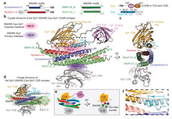
Figure 1. Crystal structures of the Syt1-SNARE-Cpx-Syt1 complex.
a, Domain diagrams. The numbers delineate the boundaries of the fragments used for crystallization. TM: transmembrane region. b, Cartoon representation of the Syt1-SNARE-Cpx-Syt1 C2AB crystal structure. The Syt1 C2B domain (orange), Cpx (cyan), and the SNARE complex (blue, red, green) form the tripartite interface. A second Syt1 C2B domain (grey, related by crystallographic symmetry) forms the primary interface with the SNARE complex21. For clarity, we omitted the C2A domain of the Syt1 molecule involved in the primary interface (Extended Data Fig. 1c). c, Rotated view of panel b, showing a section that includes 310 helix T3 and α-helix HA of the Syt1 C2B domain. d, Cartoon representation of the Syt1-SNARE-Cpx-Syt1 C2B crystal structure. The molecular surface of the complete SNARE complex structure (PDB code 1N7S) is superimposed. e, Schema of the Syt1-SNARE-Cpx-Syt1 C2AB crystal structure. f, Close-up view of the tripartite interface (same orientation as in panel b), showing the continuation of α-helix HA of the Syt1 C2B domain into the central α-helix of Cpx. Helical dipoles are indicated by δ+ and δ−.

