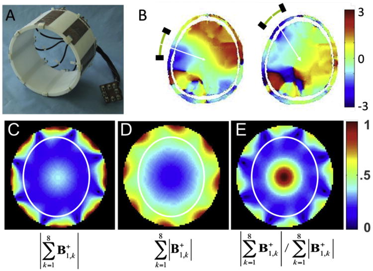
Fig. 9.

Eight channel transmit/receive RF coil (A) and experimental relative phases measured in the human head from two different individual elements of this coil (B). Lower row shows experimentally measured transmit B1 magnitude in a cylindrical “phantom” when the individual transmit B1 vectors from each channel are first experimentally determined, transmitting one channel at a time and receiving with all channels, and subsequently are added according to the constructs shown below each figure (the color code is in arbitrary units) The white ellipse in C, D, and E depicts approximate boundaries of a human head. Adapted from (Van de Moortele et al., 2005).
