Abstract
This article is based on a presentation at the meeting of the Japanese Society of Magnetic Resonance in Medicine in September 2016. The purpose is to review the technical developments which have contributed to the current status of contrast-enhanced magnetic resonance angiography (CE-MRA) and to indicate related emerging areas of study. Technical developments include MRI physics-based innovations as well as improvements in MRI engineering. These have collectively addressed not only early issues of timing and venous suppression but more importantly have led to an improvement in spatiotemporal resolution of CE-MRA of more than two orders of magnitude compared to early results. This has allowed CE-MRA to be successfully performed in virtually all vascular territories of the body. Contemporary technical areas of study include improvements in implementation of high rate acceleration, extension of high performance first-pass CE-MRA across multiple imaging stations, expanded use of compressive sensing techniques, integration of Dixon-based fat suppression into CE-MRA sequences, and application of CE-MRA sequences to dynamic-contrast-enhanced perfusion imaging.
Keywords: contrast-enhanced magnetic resonance angiography, Dixon imaging, acceleration methods
Introduction
In the time since its early description in the mid-1990s1,2 contrast-enhanced (CE) MRA has undergone major technical advances which have improved the speed, reliability, and extent of applications. MR imaging physics-related innovations as well as MR engineering developments have contributed to this advance. Using the specific metric of spatiotemporal resolution to quantify performance, modern-day CE-MRA is superior to that of initial CE-MRA reports by well over two orders of magnitude. Multiple individual technical improvements contributing to this have been documented in the literature over this time period, and there have also been a number of review articles which have covered various aspects of this evolution.3,4 This work, which is based on a presentation made at the September 2016 Japanese Society of Magnetic Resonance in Medicine, briefly reviews these major advances which have led to the current high level of performance. These include means for providing reliable timing and venous suppression, and multiple techniques such as view sharing and parallel acquisition for increasing the frame rate. This work also identifies contemporary applications and directions of CE-MRA and related methodologies, including acceleration optimization, fluoroscopic tracking, compressive sensing, Dixon-based CE-MRA, and dynamic-contrast-enhanced MRI.
Contributors to Current Performance of CE-MRA
Identification of initial challenges
Early developers of contrast-enhanced MRA not only recognized the potential value of the method but also identified a number of major limitations which, if addressed, would provide improved performance. These early limitations included a fundamental image-quality-related metric of inadequate spatial resolution as well as reliability issues such as mismatched timing of the MRI data acquisition to the arterial contrast bolus passage and undesirable venous enhancement. The first of these, limited spatial resolution, is common to many MR imaging sequences, and selection of resolution is done while considering multiple factors such as scan time and signal-to-noise ratio (SNR). Because the contrast agent provided such a large increase in the signal in the T1-weighted gradient echo sequence, it was possible to reduce to reduce the TR, still retain much of the signal, and provide improved spatial resolution per unit scan time. Investigators quickly implemented shorter TR times vs. the 14 msec TR used in early studies.2 The repetition time of a gradient echo sequence is limited by the gradient system, and identification of the value of short TR times in CE-MRA as well as in other speed-sensitive applications as cardiac MRI provided the impetus to equipment manufacturers to develop improved gradient systems. Today on whole body MRI scanners repetition times in the 3–5 msec range are used for CE-MRA, the specific value depending on various factors such the number of readout points and signal bandwidth.
Synchronization of acquisition to contrast bolus
The reliability-related issue of mismatched timing can to some extent be addressed with faster acquisition. However, specific means were developed to address these which are still used today. With one approach a small, 1–2 ml test bolus was imaged with a low resolution, rapid scan to first determine the time delay from injection to contrast arrival, and that delay was then used in the subsequent high-resolution scan.5 An alternative method used bolus monitoring6 or fluoroscopic triggering7 both of which continuously monitored the targeted vascular site using real-time MRI immediately after injection and triggered the high-resolution 3D scan once contrast arrival was observed.
Reduction of venous enhancement
Venous enhancement can be avoided if the CE-MRA acquisition is limited to the arterial, pre-venous phase. However, even with contemporary gradient systems this is not always possible. This was addressed by the development of sampling strategies of 3D k-space which timed the central k-space sampling to the arterial phase of the contrast, prior to the venous phase.8,9 Such view ordering is referred to as “centric.” From an MRI physics standpoint, such ordering samples the low frequency k-space values of 3D k-space at the optimum time in the scan when contrast is highest (peak arterial, pre-venous) and samples the remaining k-space values subsequently (late arterial, venous) while providing enough k-space samples for a high-resolution result. Centric sampling continues to be used today for single-phase CE-MRA, and variants of an interleaved approach10 are also used in non-contrast-enhanced magnetization-prepared imaging11 and in view-shared, time-resolved sequences.12
Improvements in speed – view sharing
Additional methods were applied to CE-MRA acquisition in an attempt to provide improved speed. For time-resolved imaging the method of view sharing is commonly done. This was first described in the context of 2D acquisition.13 With this technique, samples of k-space are shared from one reconstructed image to the next, with updating of only a subset of the samples. This allows the rate of image updates to be faster than the rate to fully sample k-space for a single image. For Cartesian-sampled acquisition, central k-space can be sampled more frequently than peripheral k-space, providing improvement in apparent temporal resolution. View sharing was first applied to 3D time-resolved CE-MRA with the time resolved imaging of contrast kinetics (TRICKS) technique,14 and other sequences using view sharing have also been developed such as keyhole,15 time-resolved angiography with interleaved stochastic trajectories (TWIST),16 cartesian acquisition with projection like reconstruction (CAPR),17 and dIfferential subsampling with cartesian ordering (DISCO).18 These are further explained in a review article within the context of temporal acceleration techniques.19
Improvements in speed – parallel acquistiion
A pivotal development for increasing the speed of acquisition in CE-MRA is parallel acquisition. This has been well reviewed in the literature,20,21 with the fundamental approaches based either in image space22 or k-space.23 For both cases the rationale is to sample the MRI signal simultaneously with multiple receiver coils and to use the differential sensitivity of individual coil elements across the volume to discriminate the magnetization at different pixels. This provides a reduction in the number of repetitions of the acquisition by the acceleration factor R. Similar to view sharing, this too was first described in the context of 2D acquisition, but extension to 3D acquisition24 was particularly valuable for CE-MRA. The unraveling of the individual magnetizations from the measured signals comes with a penalty of reduction of SNR in proportion to and the g-factor.22 However, similar to the argument made earlier with respect to reduction of TR, the high vascular signal of the contrast-enhanced blood allows some SNR reduction with little penalty in diagnostic quality.
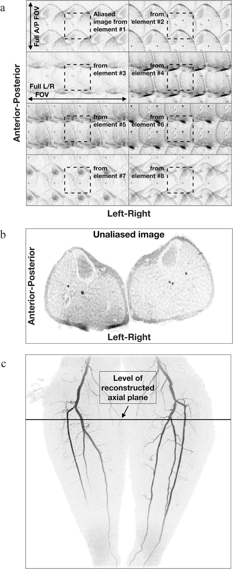
CE-MRA was identified as an early application of acceleration techniques.25 Subsequently, acceleration factors have arguably been pushed to the highest practical values in CE-MRA vs. any other application in MRI. There are reasons for this. First, because CE-MRA is generally performed with a 3D acquisition, it immediately lends itself to acceleration performed along the phase encoding and slice encoding directions; i.e. 2D acceleration. For a given acceleration factor R, 2D acceleration better retains SNR than 1D acceleration. Second, CE-MRA is generally performed in a coronal or sagittal format in which the frequency direction is superior-inferior (S/I). This means that the phase and slice encoding directions are within the transverse plane. Acceleration is particularly robust in terms of low g-factors when coil elements can be placed on opposite sides of the patient and face each other along the acceleration direction. When the phase encoding plane is transverse, circumferentially oriented coil arrays provide this for 2D acceleration. Third, the CE-MRA signal is sparse in the sense that the number of pixels which enhance due to the arterial phase contrast passage makes up a very small fraction of the total number of pixels in the volume. This reduces the signal power of pixels which are erroneously not fully resolved. An example of 2D acceleration illustrating these points taken from a 3D CE-MRA exam acquired with R = 8 is shown in Fig. 1. This study and results from all other human studies presented in this work were conducted with the approval of the Institutional Review Board (IRB).
Fig. 1.
Illustration of 2D sensitivity encoding (SENSE) in contrast-enhanced MRA. (a) Acquired images of an axial section just distal to the knees from eight coil elements formed with acceleration factor R = 4 (left/right) × 2 (anterior/posterior) = 8. Note the differences image to image, owing to the different coil sensitivities across the object. Also note the relatively low signal level of the unenhancing background tissue. (b) Reconstructed axial image using the data of (a). (c) Maximum Intensity Projection (MIP) from contrast-enhanced magnetic resonance angiography (CE-MRA) study of the calves. The level of the axial section used in (a) and (b) is identified.
These methods for improvement of the spatio-temporal resolution are summarized in Table 1. Also indicated is the method of partial Fourier acquisition,26 commonly used in many applications in MRI but used in CE-MRA (REFS) as well,27,28 and the general method of compressed sensing which is an area of ongoing study to be discussed presently.
Table 1.
Summary of techniques providing improvement in spatiotemporal resolution of contrast-enhanced MR angiography. Comments and values are with respect to imaging on a standard whole body system at 1.5T in 1995
| Technique | Description | Physical basis / Comments | Improvement factor |
|---|---|---|---|
| TR reduction | Reduce repetition time of gradient echo sequence | Large signal of contrast-enhanced blood compensates for signal loss in reducing TR from 14 to 3 – 5 msec. | 3–5 × |
| Partial fourier acquisition | Use known mathematical symmetry properties to sample only half of data space | Requires adequate knowledge of magnetic field inhomogeneity; can be applied in multiple directions. | 1.5–1.8 × |
| View sharing | Share phase-encoded “views” from one image to the next in the reconstruction of a time series | More frequent sampling of central vs. peripheral k-space allows the apparent temporal resolution to be improved. | 2–4 × |
| Parallel acquisition | Measure MR signal simultaneously from multiple receiver coil elements and exploit differential coil sensitivities across the object | Implement in image space (SENSE) or k-space (GRAPPA); both approaches allow periodic k-space undersampling. Applications in two phase encode directions allows higher acceleration than along only one direction. The penalty is diminished SNR. | 2–10 × |
| Compressed sensing | Synthesize unsampled data on the basis of statistical information | Minimize the error between the final image and the data set subject to possible constraints; topic continues to be of ongoing study | 2–4 × |
| Technical Facilitators | |||
| Gradients | Higher peak amplitudes and faster risetimes | Improved gradients allow shorter RF pulses, reduced TEs, and shorter TRs. | |
| Field strength | 3T and higher vs. 1.5T | Increased field provides higher intrinsic SNR. | |
| Multi-element receiver coils | MRI systems with multiple receive channels and coils with potentially dozens of elements | Multi-element coils are required for effective implementation of parallel acquisition. | |
| Computation hardware | Ongoing improvements in available computation speed | Speed improvements have in general allowed the above techniques to be implemented in clinically reasonable (<5 min) reconstruction times. | |
GRAPPA, Generalized autocalibrating partially parallel acquisitions; SNR, signal-to-noise ratio.
Technical facilitators
Multiple technical factors have also contributed to the improvements in CE-MRA seen over the last two decades. These are also shown in Table 1. As mentioned previously, high performance gradients, as typically specified by peak amplitude and maximum slew rate, allow reduced repetition times. Use of magnets with field strength of 3T has become much more common than at the 1.5T fields widely used in the 1990s, providing improved intrinsic SNR and further enabling methods designed to provide increased speed at the expense of SNR. Critical to the implementation of acceleration methods is the availability of high-count coil arrays having appropriate geometries. Many modern systems have arrays with literally dozens of elements built into the patient table and come equipped with additional multicoil arrays. Distinct from the coil arrays themselves, the number of receiver channels available on MRI systems has also grown in number, allowing data from multiple coil elements to be sampled simultaneously. Finally, although not specific to MRI, improvements in fundamental computation speed have also been important. This allows a time series of high-resolution 3D CE-MRA images to be reconstructed in clinically acceptable times, e.g. within 5 minutes of completion of the acquisition.
Contemporary Applications
Acceleration optimization
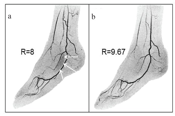
As stated earlier, 2D acceleration is well-matched to 3D CE-MRA, and this synergy has led to the routine use of high acceleration factors, e.g. R ≥ 8. This in turn has identified what is another important choice or degree of freedom, namely how should the acceleration be implemented in the 2D undersampling of kY-kZ space. Several approaches have been developed to address this. One is the technique of Controlled Aliasing in Parallel Imaging Results IN Higher Acceleration (CAIPIRINIHA)29 in which multiple undersampling kernels which all provide the same net undersampling are considered. Depending on the object under study, the directions and displacements of possible aliased points can be more benign with some kernels vs. others. Related to this has been the development of acceleration apportionment.30 When applied to 2D SENSE this method optimizes which acceleration pair (RY, RZ) provides noise-optimized performance for a given acceleration R = RY × RZ. Implementation of CAIPIRINHA and 2D SENSE in practice requires that coil calibration data be collected, typically prior to the contrast-enhanced run. This information can then be used in an optimization routine which quickly determines the optimum acceleration parameters. An example of Acceleration Apportionment is shown in Fig. 2.
Fig. 2.
Illustration of acceleration apportionment. (a) Still image from time-resolved contrast-enhanced magnetic resonance angiography (CE-MRA) exam of the feet acquired with 2D sensitivity encoding (SENSE) with R = RY × RZ = 2 × 4 = 8. Note region of patchy noise (white arrows) which occurs in areas with a high level of aliasing with these acceleration factors. (b) Still image made from the same subject as (a) but acquired in a CE-MRA exam on a different day. Acceleration apportionment resulted in higher acceleration factor R = RY × RZ = 2.87 × 3.37 = 9.67 but also reduced noise in the problematic region identified in (a). Subtle differences in the degree of filling of contrast in the vasculature are due to slight day-to-day physiological differences. (Reprinted, with permission, from Weavers et al.30).
Another approach which can be used to improve performance is to attempt to identify pixels which should have zero signal and in effect exclude them from the reconstruction. Although this is commonly done for such pixels in the air outside the object, this can also be applied to pixels within the object which are known to not have the targeted behavior such as contrast enhancement or some other temporal pattern. Examples include use of prior information in constrained reconstruction,31 iterative support detection,32 and vascular masking.33
Fluoroscopic tracking
Fluoroscopic tracking integrates many of the individual methods discussed thus far to provide a means for performing CE-MRA along the extended field of view of the peripheral vasculature with table advance accurately synchronized to transit of the arterial phase of the contrast bolus. Assume for purposes of discussion that three table stations are necessary (pelvis, thighs, calves) and the goal is to get diagnostic quality 3D CE-MRA images of the arterial phase at each station. The idea of fluoroscopic tracking is to start by imaging the most proximal (pelvis) station with a time-resolved CE-MRA sequence and reconstruct the images in real time. When the contrast bolus has traversed the entire S/I field of view, the operator then triggers table advance. This advance is completed within several seconds, and imaging of the next (thighs) stations ensues. The process is then repeated: when the operator observes that contrast has traversed the thigh station, he/she triggers table advance to the final (calves) station. Although perhaps easy to conceptualize, the method is particularly challenging because of the rapid advance of contrast, particularly in the thigh station. The acquisition sequence needs to have an adequately short frame time to allow accurate portrayal of bolus advance but also provide high spatial resolution so that the real-time images themselves have diagnostic quality. This latter requirement that the real-time images themselves be of diagnostic quality is the critical differentiator of fluoroscopic tracking with fluoroscopic triggering. For triggering, the images are coarse, 2D sections with limited spatial resolution, inadequate for diagnosis but perfectly adequate for visualizing contrast bolus arrival.
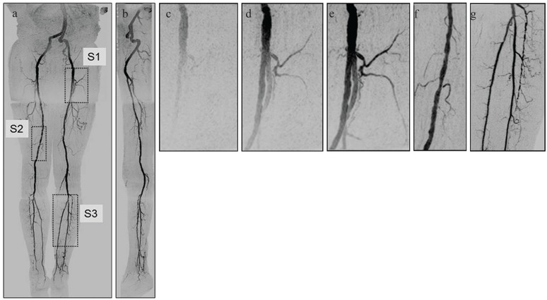
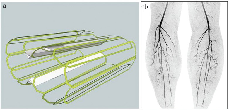
The initial experimental implementation of fluoroscopic tracking is described by Johnson et al.34, and sample results are shown in Fig. 3. More recently, to provide a shorter frame time (2.1 vs. 2.5 sec) for the thigh station as well as increased resolution per unit time for the calves station, the coil arrays have been modified.35 The thigh array now uses narrower tapered elements for improved fitting of the array to the body habitus, and the calf coil uses 16 vs. 8 elements, as shown in Fig. 4.
Fig. 3.
Illustration of fluoroscopic tracking acquired in 81-year-old male. (a) Coronal Maximum Intensity Projection (MIP) showing the peak arterial frame for each of the three stations used. (b) Sagittal MIP. (c–e) Targeted MIPs taken from region S1 from the first (pelvis) station of (a) showing the progressive filling of contrast-enhanced blood as seen in the real-time display. Frame time was 2.5 sec. Upon detecting distal arterial filling in the first (pelvis) station, the operator triggered table advance. (f) Targeted MIP taken from Region S2 of (a) from the second (thigh) station. This image was formed from data from only two 2.5 sec long frames. (g) Targeted MIP taken from Region S3 of (a) from the third (calves) station. Frame time is 5.2 sec. Although this subject was recruited as a healthy volunteer, multiple low-grade stenoses are seen in the thigh and calf arteries, and the anterior tibial artery seen in (g) is partially occluded. (Reprinted, with permission, from Johnson et al.34).
Fig. 4.
(a) Schematic diagram of 16-element circumferential receiver array for imaging the calves. (b) Coronal Maximum Intensity Projection (MIP) from image taken from time-resolved contrast-enhanced magnetic resonance angiography (CE-MRA) study of the calves using the coil of (a). Acquisition was done using R = RY × RZ = 6 × 2 = 12 as well as partial Fourier undersampling of 1.8, yielding net acceleration factor of 21.6. Frame time was 3.5 sec with 1 mm isotropic spatial resolution.
Compressive sensing
Another distinct area that has had an impact in CE-MRA is compressive sensing, a method by which undersampled data can be accounted for statistically.36 This can be used in various ways. Examples include increased frame rates,37 retention of some of the lost SNR due to acceleration,38 reduction of the temporal footprint of view-shared acquisition to improve the fidelity in portrayal of transient signals,39 and resolution of both respiratory and cardiac phases in time-resolved CE-MRA.12 Because these methods typically require identification of a statistically optimum solution, often done iteratively, the implementation is more computationally involved than, say, performing a deterministic 3D Fourier transformation of a fully-sampled data set. Ongoing improvements in computation speed have facilitated the practical implementation of compressive sensing.40
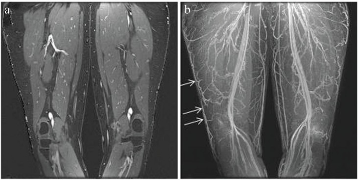
Dixon CE-MRA
Fat-water imaging based on the Dixon technique41 has been used extensively in MRI for many applications.42–44 However, recently it has been of interest to use Dixon methods in CE-MRA. The rationale is as follows. In many applications of CE-MRA, it is necessary to subtract a pre-contrast mask image from the contrast-enhanced image to eliminate the relatively bright signals of fat in the unsubtracted gradient echo images. However, if there is any subject motion between acquisition of the subtracted and unsubtracted images, the resultant motion artifacts can interfere with interpretation. Dixon CE-MRA avoids this by performing fat suppression as part of the contrast-enhanced acquisition. The contrast-enhanced blood is included within the water image. Although the water-containing, non-enhancing background tissue is still retained in the final water image, it is generally of low enough signal that it does not interfere with visualization of the enhancing vasculature. The application of dual-echo Dixon acquisition to CE-MRA was described recently by Leiner et al.45.
Dixon CE-MRA requires that the magnetic field inhomogeneity ΔB0 be determined. Together with the complex-valued water and fat magnetizations, this results in five unknowns. However, using a signal model46 which assumes that fat and water have the same initial phase ϕ0 immediately after excitation reduces the number of real-valued unknowns to four (W, F, ΔB0, ϕ0), where W and F are the real-valued magnitudes of the water and fat magnetization vectors. This system of unknowns can be unambiguously determined using two complex-valued measurements as provided in dual-echo Dixon acquisition. Even with this simplification, accurate determination of ΔB0 is one of the most challenging aspects of Dixon imaging. In particular, when the inhomogeneity gets larger than several ppm, determination of ΔB0 typically requires that 2π wraps in the phase difference between the two echo times be accurately resolved. A number of recent publications describe how this can be done.47–49 A related aspect of dual-echo Dixon imaging is the selection of the echo times. These are conventionally chosen so that the phase difference between the complex fat and water magnetizations at the two echo times used is approximately π radians. For example, at a field strength of 3T with a corresponding fat-water frequency difference of approximately 440 Hz, the times between the two echoes used should be (1/2) × (440 Hz)−1 = 1.1 msec or an odd multiple thereof. Modern approaches provide some flexibility with this.48 Sample dual-echo Dixon results are shown in Fig. 5.
Fig. 5.
Example of dual-echo Dixon contrast-enhanced MR angiography. (a) Coronal partition of the water image showing the bright, contrast-enhanced blood, the gray, unenhanced muscle which is included in the water image, and the black, suppressed fat. (b) Coronal Maximum Intensity Projection (MIP) of the water image at a late contrast phase showing the enhancing arteries and veins. The overlying skin has been first been removed. Note in particular the high visibility of the veins contained within the subcutaneous fat (arrows).
It is possible to perform Dixon-based fat-suppressed CE-MRA with a single echo.50,51 This requires that a calibration be performed prior to the single-echo scan which provides information about ΔB0 and the assumed fat and water post-excitation phase ϕ0. However, assuming that these two quantities do not change in the subsequent contrast-enhanced scan, one complex echo can be used to solve for the two remaining unknowns, W and F. SNR for single-echo Dixon acquisition is optimized when water and fat can most readily be distinguished in the complex signal. This occurs when the phase angle between them is largest, namely at π/2, 3π/2, 5π/2, etc. radians. At a field strength of 3T this corresponds to gradient echo times of 0.56 msec and odd multiples thereof.
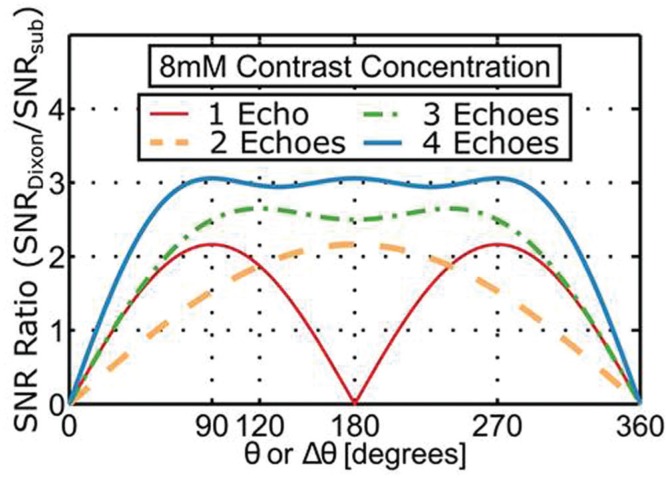
Another aspect of Dixon CE-MRA which should be noted is the superiority of both SNR and contrast-to-noise ratio (CNR) vs. conventional time subtraction. This has been analyzed theoretically and shown in phantom studies,51 and corroborated in measurements made from clinical CE-MRA exams.45 Interestingly, this superiority over conventional subtraction holds not only for dual-echo but even for single-echo Dixon CE-MRA. Sample results from that analysis are shown in Fig. 6.
Fig. 6.
Plot of the ratio of signal-to-noise ratio (SNR) of Dixon vs. conventional time subtraction contrast-enhanced magnetic resonance angiography (CE-MRA) as a function of the fat-water phase angle between the gradient echo times used for an assumed 8 mm contrast concentration. For the single-echo case the angle is the absolute angle between the complex fat and water magnetizations. (Reprinted, with permission, from Stinson et al.51).
Applications to DCE-MRI
Organ perfusion is commonly assessed in MRI by intravenous administration of contrast agent followed by generation of a time series of images of the target organ. Two general approaches are used: (i) Dynamic Susceptibility Contrast (DSC) MRI and (ii) Dynamic Contrast-enhanced (DCE) MRI.52 The first of these uses an echo-planar sequence with adequately long gradient echo time to allow signal modulation due to R2*. The second uses a T1-sensitive gradient echo acquisition and associates signal level with bolus transit. That is to say, the pulse sequence used for DCE-MRI is virtually identical to that used for CE-MRA. Thus, many of the innovations and developments which have contributed to the technical advance of CE-MRA are also applicable to DCE-MRI sequences.
Although both CE-MRA and DCE-MRI use a T1-weighted gradient echo sequence, there are some differences in how it is applied in the two applications. Rather than the coronal or sagittal format of CE-MRA, an axial slab is typically used for DCE-MRI, such as for prostate or liver. This casts slice encoding along the S/I direction. Second, the signal of interest is no longer just the arterial phase of the contrast bolus, but rather the potentially more gradual onset and washout of contrast within the target organ. This signal change is typically smaller in magnitude than the arterial enhancement. Third, because the enhancement occurs in regions of organs rather than blood vessels, the resultant 3D image is no longer as sparse as for CE-MRA of the same volume. These factors all represent alterations from those discussed earlier which synergistically match 3D CE-MRA with 2D acceleration. Consequently, it is unlikely that the large acceleration factors (R ≥ 8) of CE-MRA are attainable with DCE-MRI.
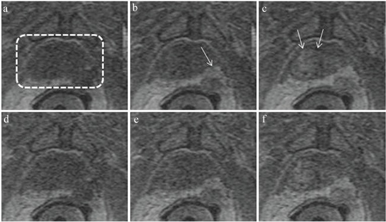
Figure 7 shows images taken from a DCE-MRI exam of the prostate. The pulse sequence used is an adaptation of that developed for time-resolved 3D CE-MRA of the abdomen. Slab selection and slice encoding are along the S/I direction. The acceleration factor used was RY × RZ = 2.49 × 1.12 = 2.78. As with accelerated 3D CE-MRA it is important that the coil array effectively allows the targeted acceleration. Figure 7a–c was formed with a 32-element receiver coil, and Fig 7d–f using 12 elements from the same contrast-enhanced acquisition. As reported recently in a 50-patient series,53 the 32-element coil consistently provided improved SNR, as suggested in these results.
Fig. 7.
Illustration of dynamic contrast-enhanced-magnetic resonance imaging (DCE-MRI) of the prostate. Images are all subregions of an axial section through the prostate gland acquired with a DCE-MRI sequence with 6.5 sec frame time. The prostate is contained within the dashed box of (a). Images (a–c) were acquired with a 32-coil array at 32.5, 45.5, and 58.5 sec post intravenous injection of contrast material and illustrate progressive enhancement of posterolateral lesion (b, arrow) and central region (c, arrow). Images (d–f) were formed with using data from only 12 of the 32 coils, illustrating loss of signal-to-noise ratio (SNR).
Conclusions
Contrast-enhanced MRA has undergone major improvements since its initial description 20 years ago which have collectively provided two orders of magnitude improvement in spatiotemporal resolution. The physics innovations and engineering developments which have provided this include reduced repetition times as facilitated by improved gradients, various parallel acquisition approaches, particularly in two directions, methods such as view sharing which enhance frame rate, and multiple coil arrays which make high acceleration factors practical. Although outside the scope of this work, 3D CE-MRA has been applied to virtually all vascular territories of the body.
Topics of a more contemporary nature related to and originating from 3D CE-MRA include means for best determining how to implement high acceleration factors, the method of fluoroscopic triggering for generation of time-resolved CE-MRA images along the entire peripheral vasculature, multiple uses of compressive sensing, the application of Dixon-based fat suppression to CE-MRA, and the application of technologies developed for CE-MRA to dynamic contrast-enhanced perfusion MRI.
Acknowledgments
We acknowledge the support of NIH EB000212, RR018898, and DOD W81XWH-15-1-0431.
Footnotes
Conflicts of Interest
The authors declare that they have no conflicts of interest.
References
- 1.Prince MR. Gadolinium-enhanced MR aortography. Radiology 1994; 191:155–164. [DOI] [PubMed] [Google Scholar]
- 2.Prince MR, Narasimham DL, Stanley JC, et al. Breath-hold gadolinium-enhanced MR angiography of the abdominal aorta and its major branches. Radiology 1995; 197: 785–792. [DOI] [PubMed] [Google Scholar]
- 3.Grist TM, Mistretta CA, Strother CM, Turski PA. Time-resolved angiography: past, present, and future. J Magn Reson Imaging 2012; 36:1273–1286. [DOI] [PubMed] [Google Scholar]
- 4.Riederer SJ, Haider CR, Borisch EA, Weavers PT, Young PM. Recent advances in 3D time-resolved contrast-enhanced MR angiography. J Magn Reson Imaging 2015; 42:3–22. [DOI] [PMC free article] [PubMed] [Google Scholar]
- 5.Earls JP, Rofsky NM, DeCorato DR, Krinsky GA, Weinreb JC. Breath-hold single-dose gadolinium-enhanced three-dimensional MR aortography: usefulness of a timing examination and MR power injector. Radiology 1996; 201: 705–710. [DOI] [PubMed] [Google Scholar]
- 6.Foo TK, Saranathan M, Prince MR, Chenevert TL. Automated detection of bolus arrival and initiation of data acquisition in fast, three-dimensional, gadolinium-enhanced MR angiography. Radiology 1997; 203:275–280. [DOI] [PubMed] [Google Scholar]
- 7.Wilman AH, Riederer SJ, King BF, Debbins JP, Rossman PJ, Ehman RL. Fluoroscopically triggered contrast-enhanced three-dimensional MR angiography with elliptical centric view order: application to the renal arteries. Radiology 1997; 205:137–146. [DOI] [PubMed] [Google Scholar]
- 8.Wilman AH, Riederer SJ. Performance of an elliptical centric view order for signal enhancement and motion artifact suppression in breath-hold three-dimensional gradient echo imaging. Magn Reson Med 1997; 38:793–802. [DOI] [PubMed] [Google Scholar]
- 9.Willinek WA, Gieseke J, Conrad R, et al. Randomly segmented central k-space ordering in high-spatial-resolution contrast-enhanced MR angiography of the supraaortic arteries: initial experience. Radiology 2002; 225:583–588. [DOI] [PubMed] [Google Scholar]
- 10.Wilman AH, Riederer SJ. Improved centric phase encoding orders for three-dimensional magnetization-prepared MR angiography. Magn Reson Med 1996; 36:384–392. [DOI] [PubMed] [Google Scholar]
- 11.Prieto C, Doneva M, Usman M, et al. Highly efficient respiratory motion compensated free-breathing coronary MRA using golden-step Cartesian acquisition. J Magn Reson Imaging 2015; 41:738–746. [DOI] [PubMed] [Google Scholar]
- 12.Cheng JY, Zhang T, Ruangwattanapaisarn N, et al. Free-breathing pediatric MRI with nonrigid motion correction and acceleration. J Magn Reson Imaging 2015; 42: 407–420. [DOI] [PMC free article] [PubMed] [Google Scholar]
- 13.Riederer SJ, Tasciyan T, Farzaneh F, Lee JN, Wright RC, Herfkens RJ. MR fluoroscopy: technical feasibility. Magn Reson Med 1988; 8:1–15. [DOI] [PubMed] [Google Scholar]
- 14.Korosec FR, Frayne R, Grist TM, Mistretta CA. Time-resolved contrast-enhanced 3D MR angiography. Magn Reson Med 1996; 36:345–351. [DOI] [PubMed] [Google Scholar]
- 15.Willinek WA, Hadizadeh DR, von Falkenhausen M, et al. 4D time-resolved MR angiography with keyhole (4D-TRAK): more than 60 times accelerated MRA using a combination of CENTRA, keyhole, and SENSE at 3.0T. J Magn Reson Imaging 2008; 27:1455–1460. [DOI] [PubMed] [Google Scholar]
- 16.Lim RP, Shapiro M, Wang EY, et al. 3D time-resolved MR angiography (MRA) of the carotid arteries with time-resolved imaging with stochastic trajectories: comparison with 3D contrast-enhanced Bolus-Chase MRA and 3D time-of-flight MRA. AJNR Am J Neuroradiol 2008; 29:1847–1854. [DOI] [PMC free article] [PubMed] [Google Scholar]
- 17.Haider CR, Hu HH, Campeau NG, Huston J, Riederer SJ. 3D high temporal and spatial resolution contrast-enhanced MR angiography of the whole brain. Magn Reson Med 2008; 60:749–760. [DOI] [PMC free article] [PubMed] [Google Scholar]
- 18.Saranathan M, Rettmann DW, Hargreaves BA, Clarke SE, Vasanawala SS. Differential subsampling with Cartesian ordering (DISCO): a high spatio-temporal resolution Dixon imaging sequence for multiphasic contrast enhanced abdominal imaging. J Magn Reson Imaging 2012; 35:1484–1492. [DOI] [PMC free article] [PubMed] [Google Scholar]
- 19.Tsao J, Kozerke S. MRI temporal acceleration techniques. J Magn Reson Imaging 2012; 36:543–560. [DOI] [PubMed] [Google Scholar]
- 20.Glockner JF, Hu HH, Stanley DW, Angelos L, King K. Parallel MR imaging: a user’s guide. Radiographics 2005; 25:1279–1297. [DOI] [PubMed] [Google Scholar]
- 21.Deshmane A, Gulani V, Griswold MA, Seiberlich N. Parallel MR imaging. J Magn Reson Imaging 2012; 36:55–72. [DOI] [PMC free article] [PubMed] [Google Scholar]
- 22.Pruessmann KP, Weiger M, Scheidegger MB, Boesiger P. SENSE: sensitivity encoding for fast MRI. Magn Reson Med 1999; 42:952–962. [PubMed] [Google Scholar]
- 23.Griswold MA, Jakob PM, Heidemann RM, et al. Generalized autocalibrating partially parallel acquisitions (GRAPPA). Magn Reson Med 2002; 47:1202–1210. [DOI] [PubMed] [Google Scholar]
- 24.Weiger M, Pruessmann KP, Boesiger P. 2D SENSE for faster 3D MRI. MAGMA 2002; 14:10–19. [DOI] [PubMed] [Google Scholar]
- 25.Weiger M, Pruessmann KP, Kassner A, et al. Contrast-enhanced 3D MRA using SENSE. J Magn Reson Imaging 2000; 12:671–677. [DOI] [PubMed] [Google Scholar]
- 26.Noll DC, Nishimura DG, Macovski A. Homodyne detection in magnetic resonance imaging. IEEE Trans Med Imaging 1991; 10:154–163. [DOI] [PubMed] [Google Scholar]
- 27.Hu HH, Madhuranthakam AJ, Kruger DG, Glockner JF, Riederer SJ. Combination of 2D sensitivity encoding and 2D partial fourier techniques for improved acceleration in 3D contrast-enhanced MR angiography. Magn Reson Med 2006; 55:16–22. [DOI] [PMC free article] [PubMed] [Google Scholar]
- 28.Krishnam MS, Tomasian A, Lohan DG, Tran L, Finn JP, Ruehm SG. Low-dose, time-resolved, contrast-enhanced 3D MR angiography in cardiac and vascular diseases: correlation to high spatial resolution 3D contrast-enhanced MRA. Clin Radiol 2008; 63:744–755. [DOI] [PubMed] [Google Scholar]
- 29.Breuer FA, Blaimer M, Mueller MF, et al. Controlled aliasing in volumetric parallel imaging (2D CAIPIRINHA). Magn Reson Med 2006; 55:549–556. [DOI] [PubMed] [Google Scholar]
- 30.Weavers PT, Borisch EA, Johnson CP, Riederer SJ. Acceleration apportionment: a method of improved 2D SENSE acceleration applied to 3D contrast-enhanced MR angiography. Magn Reson Med 2014; 71:672–680. [DOI] [PMC free article] [PubMed] [Google Scholar]
- 31.Johnson KM, Velikina J, Wu Y, Kecskemeti S, Wieben O, Mistretta CA. Improved waveform fidelity using local HYPR reconstruction (HYPR LR). Magn Reson Med 2008; 59:456–462. [DOI] [PMC free article] [PubMed] [Google Scholar]
- 32.Liang D, DiBella EV, Chen RR, Ying L. k-t ISD: dynamic cardiac MR imaging using compressed sensing with iterative support detection. Magn Reson Med 2012; 68:41–53. [DOI] [PMC free article] [PubMed] [Google Scholar]
- 33.Stinson EG, Borisch EA, Johnson CP, Trzasko JD, Young PM, Riederer SJ. Vascular masking for improved unfolding in 2D SENSE-accelerated 3D contrast-enhanced MR angiography. J Magn Reson Imaging 2014; 39:1161–1170. [DOI] [PMC free article] [PubMed] [Google Scholar]
- 34.Johnson CP, Weavers PT, Borisch EA, et al. Three-station three-dimensional bolus-chase MR angiography with real-time fluoroscopic tracking. Radiology 2014; 272: 241–251. [DOI] [PMC free article] [PubMed] [Google Scholar]
- 35.Weavers PT, Borisch EA, Hulshizer TC, et al. Improved receiver arrays and optimized parallel imaging accelerations applied to time-resolved 3D fluoroscopically tracked peripheral runoff CE-MRA. Magn Reson Imaging 2016; 34:280–288. [DOI] [PMC free article] [PubMed] [Google Scholar]
- 36.Lustig M, Donoho D, Pauly JM. Sparse MRI: the application of compressed sensing for rapid MR imaging. Magn Reson Med 2007; 58:1182–1195. [DOI] [PubMed] [Google Scholar]
- 37.Mistretta CA, Wieben O, Velikina J, et al. Highly constrained backprojection for time-resolved MRI. Magn Reson Med 2006; 55:30–40. [DOI] [PMC free article] [PubMed] [Google Scholar]
- 38.Trzasko JD, Haider CR, Borisch EA, et al. Sparse-CAPR: highly accelerated 4D CE-MRA with parallel imaging and nonconvex compressive sensing. Magn Reson Med 2011; 66:1019–1032. [DOI] [PMC free article] [PubMed] [Google Scholar]
- 39.Rapacchi S, Natsuaki Y, Plotnik A, et al. Reducing view-sharing using compressed sensing in time-resolved contrast-enhanced magnetic resonance angiography. Magn Reson Med 2015; 74:474–481. [DOI] [PubMed] [Google Scholar]
- 40.Borisch EA, Trzasko JD, Froemming AT, et al. Faster-than-acquisition 4D sparse reconstruction for Cartesian 2D SENSE-type acquisition. 23rd Annual Mtg, ISMRM; Toronto: 2015; 1580. [Google Scholar]
- 41.Dixon WT. Simple proton spectroscopic imaging. Radiology 1984; 153:189–194. [DOI] [PubMed] [Google Scholar]
- 42.Reeder SB, Wen Z, Yu H, et al. Multicoil Dixon chemical species separation with an iterative least-squares estimation method. Magn Reson Med 2004; 51:35–45. [DOI] [PubMed] [Google Scholar]
- 43.Ma J. Breath-hold water and fat imaging using a dual-echo two-point Dixon technique with an efficient and robust phase-correction algorithm. Magn Reson Med 2004; 52:415–419. [DOI] [PubMed] [Google Scholar]
- 44.Xiang QS. Two-point water-fat imaging with partially-opposed-phase (POP) acquisition: an asymmetric Dixon method. Magn Reson Med 2006; 56:572–584. [DOI] [PubMed] [Google Scholar]
- 45.Leiner T, Habets J, Versluis B, et al. Subtractionless first-pass single contrast medium dose peripheral MR angiography using two-point Dixon fat suppression. Eur Radiol 2013; 23:2228–2235. [DOI] [PubMed] [Google Scholar]
- 46.Bydder M, Yokoo T, Yu H, Carl M, Reeder SB, Sirlin CB. Constraining the initial phase in water-fat separation. Magn Reson Imaging 2011; 29:216–221. [DOI] [PMC free article] [PubMed] [Google Scholar]
- 47.Hernando D, Kellman P, Haldar JP, Liang ZP. Robust water/fat separation in the presence of large field inhomogeneities using a graph cut algorithm. Magn Reson Med 2010; 63:79–90. [DOI] [PMC free article] [PubMed] [Google Scholar]
- 48.Eggers H, Brendel B, Duijndam A, Herigault G. Dual-echo Dixon imaging with flexible choice of echo times. Magn Reson Med 2011; 65:96–107. [DOI] [PubMed] [Google Scholar]
- 49.Stinson EG, Trzasko JD, Fletcher JG, Riederer SJ. Dual echo Dixon imaging with constrained phase signal model and graph cuts reconstruction. Magn Reson Med 2017; 2 February. doi: 10.1002/mrm.26620 [Epub ahead of print]. [DOI] [PMC free article] [PubMed]
- 50.Yu H, Reeder SB, McKenzie CA, et al. Single acquisition water-fat separation: feasibility study for dynamic imaging. Magn Reson Med 2006; 55:413–422. [DOI] [PubMed] [Google Scholar]
- 51.Stinson EG, Trzasko JD, Weavers PT, Riederer SJ. Dixon-type and subtraction-type contrast-enhanced magnetic resonance angiography: a theoretical and experimental comparison of SNR and CNR. Magn Reson Med 2015; 74:81–92. [DOI] [PMC free article] [PubMed] [Google Scholar]
- 52.Lacerda S, Law M. Magnetic resonance perfusion and permeability imaging in brain tumors. Neuroimg Clin N Am 2009; 19:527–557. [DOI] [PubMed] [Google Scholar]
- 53.Riederer SJ, Borisch EA, Froemming AT, et al. Improved performance of prostate DCE-MRI using a 32-coil vs. 12-coil receiver array. Magn Reson Imaging 2017; 39:15–23. [DOI] [PMC free article] [PubMed] [Google Scholar]


