Abstract
Projection and backprojection operations are essential in a variety of image reconstruction and physical correction algorithms in CT. The distance-driven (DD) projection and backprojection are widely used for their highly sequential memory access pattern and low arithmetic cost. However, a typical DD implementation has an inner loop that adjusts the calculation depending on the relative position between voxel and detector cell boundaries. The irregularity of the branch behavior makes it inefficient to be implemented on massively parallel computing devices such as graphics processing units (GPUs). Such irregular branch behaviors can be eliminated by factorizing the DD operation as three branchless steps: integration, linear interpolation, and differentiation, all of which are highly amenable to massive vectorization. In this paper, we implement and evaluate a highly parallel branchless DD algorithm for 3D cone beam CT. The algorithm utilizes the texture memory and hardware interpolation on GPUs to achieve fast computational speed. The developed branchless DD algorithm achieved 137-fold speedup for forward projection and 188-fold speedup for backprojection relative to a single-thread CPU implementation. Compared with a state-of-the-art 32-thread CPU implementation, the proposed branchless DD achieved 8-fold acceleration for forward projection and 10-fold acceleration for backprojection. GPU based branchless DD method was evaluated by iterative reconstruction algorithms with both simulation and real datasets. It obtained visually identical images as the CPU reference algorithm.
Index Terms: branchless distance-driven, projection, backprojection, computed tomography, reconstruction, GPU
I. Introduction
X-RAY computed tomography (CT) is one of the main modern imaging modalities widely applied in clinical diagnosis [1], pharmaceutical industries [2], [3] and other non-destructive evaluations [4]. The importance of x-ray CT has never been underestimated for its high spatial resolution, high temporal resolution, and fast scanning speed. However, modern CT systems require a variety of modeling, correction, and image reconstruction algorithms to generate high quality images.
Projection and backprojection (P/BP) operations are the key components of many CT algorithms. The projection operation is widely applied in the simulation of CT imaging systems or acquisition processes [5]–[7]. Another important application of P/BP is in iterative reconstruction algorithms (IRAs), where P/BP are performed alternatively to find an optimum solution that fits the measurements and prior knowledge according to an objective function. IRAs are becoming more popular because they can improve image quality when the projection data are truncated or very noisy. It is possible to integrate IRAs with physical models, statistical models, detector response model, and prior knowledge. Despite the various advantages of IRAs, they usually demand high computational cost dominated by the P/BP operations.
To improve the computational efficiency, the distancedriven (DD) model [8], [9] is widely applied in P/BP for its highly sequential memory access pattern and low arithmetic cost on CPU platforms. Its overlapping kernel avoids high-frequency artifacts and ensures that the P/BP operators are matched. The DD model is based on the overlap length of voxel and detector cell footprints when mapped to a common axis. A typical DD implementation has an inner loop that adjusts the calculation with an if-else branch depending on the relative positions between voxel and detector cell boundaries. For fan-beam and cone-beam tomography, the patterns of voxel and detector cell boundaries are generally non-uniform when they are mapped to the common axis, resulting in irregularity and poor predictability of the branch behavior and making it difficult to effectively implement on multiple-core vector computing devices such as GPUs.
To overcome the irregular branch behavior of the original DD algorithm, Basu and De Man proposed a branchless DD algorithm [10] by factorizing the DD operation as three branchless steps: integration, linear interpolation, and differentiation. All three steps are highly parallelizable and very suitable for vectorized implementation. However, the branchless DD algorithm in [10] was only shown as a one-dimensional conceptual example. It has yet been clear how to translate the branchless concept to more realistic 2D and 3D CT geometry. In terms of the number of arithmetic operations, the branchless implementation actually requires more operations compared to the non-branchless implementation with if-else statements. On CPU platforms, it is generally believed the overhead of the branchless DD would outweigh its potential benefits in parallelism.
In the past decade, massively parallel GPU devices have become a commodity for general-purpose computing. With more of its on-chip estates allocated for computing cores but thread divergence being detrimental, GPUs seem to be a suitable platform to realize the full potential of the branchless DD. In an earlier conference publication [11], we reported a 3D implementation of branchless DD on GPU and applied it IRAs from simulation and real CT data. The algorithm utilized the texture memory and hardware interpolation on GPUs to achieved ultra-fast computational speed.
This paper extends the work in [11] by providing details of the derivation of branchless DD in 3D, and explaining how GPU threads were allocated for both forward and backprojection, and the steps undertaken by each thread to compute DD values. Pseudocode of our implementation is provided in supplementary martial. Moreover, due to the limited precision of the texture mapping hardware utilized in the branchless operation to achieve the ultra-fast speed, a substantial effort in the present study focuses on the analysis and quantification of the precision loss relative to CPU reference code. We report the measured precision loss in both the P/BP operations as single modules and in iteratively reconstructed images where error accumulation and numerical instability could be concerns. We implemented several popular non-regularized and regularized IRAs (OS-SART, PCG, FISTA, with q-GGMRF and TV penalties) on both CPU and GPU platforms. We also report results of a GPU non-branchless DD implementation and a GPU double-precision branchless DD implementation as higher-accuracy references. Finally, we propose and evaluate a “Z-line” based branchless DD backprojection to reduce the memory access times and provide better performance in certain cases.
During the peer-review process of this paper, we noticed independent conference publications on GPU implementations of branchless DD. Schlifske and Medeiros [12] reported a GPU implementation of branchless DD algorithm similar to [11]., Degirmenci, Politte, et al. [13] also used a GPU branchless DD for CT reconstruction. While the emergence of these recent publications shows increasing recognition of the merits of the branchless DD on GPU platforms, these studies lacked a complete derivation of the branchless algorithm in 3D and lacked details about how the algorithm can be mapped to GPUs. Moreover, there has not been a systematical and rigorous analysis and quantification of the precision loss in the GPU implementations. For example, these studies did not quantify the difference between GPU and CPU implementations in either single modules in iteratively reconstructed images. Schlifske and Medeiros [12] measured difference between reconstructed images relative to a ground truth phantom image, but the results could be more affected by factors such as lacking of convergence (only three iterations were used), choice of regularization, and noise in the data, instead the precision of the P/BP themselves. They also only used limited simulation data. In particular, Schlifske and Medeiros [12] attributed the precision loss to the integration step of branchless DD, but did not discuss the precision loss due to the texture mapping hardware, which we will discuss in more details in the present paper.
The rest of the paper is organized as follows. In section II, we briefly review several P/BP models and some GPU relevant CT image reconstruction works. In section III, the conventional DD algorithm and the branchless DD algorithm are reviewed. The branchless DD algorithm is extended to 3D, and its implementation on GPU is described. In section IV, the proposed GPU branchless DD model is evaluated in both speed and accuracy. In section V, some related issues are discussed and the conclusions are made.
II. Related Works and Background
A. Different P/BP models
P/BP models are different in their trade-offs between the computational speed and modelling accuracy. Ray-driven P/BP works by tracing rays through the image. The contribution from a voxel to a ray can be calculated based on the intersection length [14]–[17], or be interpolated based on the distance from the voxel to nearby rays [16], [18]. The ray-driven models usually work well for forward projection. However, they tend to introduce Moiré pattern artefacts in backprojection [8], [9]. Also, ray-driven backprojection algorithms are not straightforward to parallelize. One technique to parallelize the ray-driven backprojection is the boundary box technique [19], where the perspective projected voxel forms a convex shadow on the detector. The backprojection value from one view is the sum of detector cells inside the convex shadow respectively reweighted by intersection lengths between the voxel and x-ray paths. This method requires the traversal of detector cells inside the shadow and it is time consuming. Furthermore, the ray-driven methods also perform in a non-sequential memory access pattern, and the out-of-order memory writing makes it difficult to be highly parallelized directly.
Pixel-driven P/BP models, on the other hand, work well for backprojection but are less effective for forward projection. Pixel-driven backprojection is suitable for hardware implementation with specialized circuit [20] and is widely used for FBP algorithms when the detector array is regular [14], [16], [21]. However, pixel-driven forward projection introduces Moiré pattern artefacts [8], [9], [17]. They are also difficult to be parallelized because they access memory in a non-sequential pattern. Although the Moiré pattern artefacts in pixel-driven forward projection can be prevented with sophisticated weighting schemes [22], the increased computational complexity makes it seldom applied. It was also proposed to store the projection weightings to reduce its computational complexity [23]–[25]. However, it is impractical to be applied in CT imaging for its huge data size. For higher computational efficiency, other pixel- and ray-driven P/BP models were also proposed by simplifying the estimation of the weighting factors [21], [26], [27]. The high frequency artefacts were also reduced by designing non-standard rectangular pixel shapes[16], [28]–[30].
More accurate P/BP models have been proposed. For example, the area integral model (AIM) [31] or volume integral model (VIM) calculate the projection weighting factor by considering the intersection area or volume between the x-ray path and the pixel/voxel. The Sutherland-Hodgman clipping algorithm is one common algorithm in computer graphics to calculate the common intersection volume [32]. The clipped convex polyhedron will be decomposed into a number of tetrahedrons to calculate the volume size [33]. Both the AIM and VIM describe the intersection weighting factors in high accuracy and ensure matched forward and back operations. However, the difficulty is their high computational complexity. The AIM and VIM are difficult to be implemented and optimized for high computational performance.
It is desirable to develop P/BP models with low computational complexity and high accuracy. Two representative models are the distance driven (DD) model [8], [9] and separable footprint (SF) model [34]. Both DD and SF models accurately describe the contribution of a voxel to a detector cell and provide matched forward and back operators. Both DD and SF methods are separable, in the sense that they are both factorized into a transaxial coefficient (in the xy plane) and a longitudinal coefficient (in the z direction). The DD model replaces the ideal trapezoidal voxel footprint by the so-called overlap kernel in both dimensions, ignoring the depth of the voxel. The SF model is essentially a variation on the DD model where that approximation by the overlap kernel is only made in the z-direction, while the xy-dimension still uses the exact trapezoidal voxel footprint, aiming at a better tradeoff between accuracy and performance.
B. GPU Acceleration for CT reconstruction
The design of parallel algorithms depends on computing architectures. PC clusters [35] are very expensive and take large space, while FPGAs are difficult to program or upgrade [36], [37]. In contrast, the GPU is more flexible and receives more attention. It is initially designed to accelerate the rendering of images and video streams outputting on a display device. It features many computing cores and high bandwidth memory bus which are suitable to execute highly data-parallel and arithmetic-intensive algorithms. At the very beginning, the GPU application programming interfaces (APIs) (e.g. DirectX, OpenGL, HLSL and CG API) are only intended for computer graphics applications. To implement general purpose algorithms on GPU, programmers need to acquire the knowledge of computer graphics and represent their algorithms in graphical operation semantics. More recently, to reduce the coding difficulty, general APIs (i.e. Compute Unified Device Architecture (CUDA) [38], Open Computing Language (OpenCL) [39]) were developed. As a result, researchers and programmers only need to focus on the algorithm design instead of considering how to map their algorithms to graphic operation semantics. In this paper, we choose CUDA to implement the branchless DD P/BP model. The CUDA inherits C/C++ as an extension and is rapidly exploited in several application fields including medical imaging [40], [41].
The GPU based CT reconstruction was first proposed in [42] to accelerate a filtered backprojection algorithm. High performance backprojection algorithms on GPU and other devices have been explored [40], [43], [44]. Rohkol et al [45] developed a RabbitCT platform providing a benchmark to evaluate the performance of GPU based analytical reconstruction algorithms. Muller and his partners demonstrated an GPU-accelerated CT reconstruction and achieved high speedups with respect to their CPU counterparts [46]–[48]. They accelerated the CT reconstruction on GPU by using the RGBA channels of 2D texture operations [47] or with shading language for backprojection in FDK algorithms [48], [49]. They also investigated the efficiency of ordered subset reconstruction algorithm using conjugate gradient method in GPU [50]. CUDA based GPU acceleration for CT reconstruction was reported in [40]. The multiple GPUs acceleration in CUDA for IRAs were reported in [51], where the tasks were simply divided into several sub-problems and distributed to multiple GPUs. An abundant of research and literatures have been published focusing on the GPU-acceleration of image reconstruction algorithms [36]–[41].
III. Methods
A. Cone-beam CT Geometry
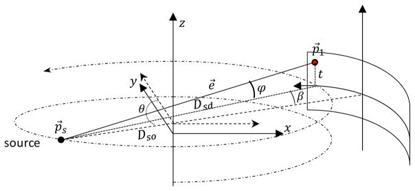
The cone-beam geometry with a circular or helical scanning trajectory is applied. In Fig. 1, a right-hand Cartesian coordinate system with an arc-detector is assumed. The x-ray source and the detector rotate simultaneously around the z-axis in a helical scanning mode. The distance from the source to the rotation center z-axis is Dso. The x-ray source position p⃗s can be calculated as sin
Fig. 1.
Circular cone-beam geometry with a curve-detector.
| (1) |
The rotation angle θ is defined counter-clockwise in the plane containing p⃗s and perpendicularly to z-axis from the direction of a vector parallel to y-axis and h is the helical pitch. When h = 0, it degrades to the well-known circular scanning trajectory. (β, t) denotes the local coordinate on an arc-detector, where β is the in-plane fan angle and t is the local Z coordinate (See Fig. 1). The coordinate of point p⃗1 on the detector can be calculated from:
| (2) |
where Dsd is the source to the detector distance. The x-ray path vector from p⃗s to p⃗1 can be normalized as
| (3) |
where φ is the polar angle calculated from
| (4) |
Let the function f(x, y, z) be the linear attenuation coefficients to be reconstructed (image volume). The line integral of the object is given by
| (5) |
where L(β, t, θ) represents the x-ray path determined by parameters β, t, and θ as well as constants Dso and Dsd,
| (6) |
On one hand, given a rotation angle θ and a point (x, y, z) between the source and the detector, its projection position p⃗1(β, t) on the detector can be calculated from
| (7) |
and
| (8) |
We assume that the sizes of the detector cells are the same with no gap. The fan angle of each detector cell is Δβ and the height of the detector cell is Δt. Given the center index of the detector(icβ, jct), the indices of the intersection point p⃗1(β, t) are
| (9) |
On the other hand, given the source position p⃗s, an x-ray path vector e⃗, and x coordinate xn on this x-ray path, the corresponding y and z coordinates can be calculated from
| (10) |
Similarly, given the y coordinate yn on this x-ray path, x and z can be calculated from
| (11) |
With the center index of the object (icx, jcy, kcz) and the voxel size (Δx, Δy, Δz), the index of the point (xm, yn, zl) in the image volume can be calculated by
| (12) |
B. Distance-Driven Model
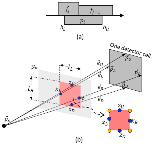
In Fig. 2(a), the normalized 1D DD interpolation from bL to bH can be represented in an integral form as
Fig. 2.
Illustration of DD models. (a) 1D DD interpolation model; (b) 2D DD integral to calculate the projection of one slice of the volumetric image.
| (13) |
Under the specific case shown in Fig. 2(a), the integral form can be represented arithmetically in [9]. For projection, the calculation of the overlapping between detector and pixel boundaries defines the traversal range for DD interpolation which is conducted by the if-else instructions. The calculation of fan-beam DD projection on one detector cell can be divided into many 1D DD interpolation sub-problems. The projection is the accumulation of the 1D DD interpolations from all rows of the image reweighted by the slope of the x-ray path and the pixel size.
In 3D DD projection, the volumetric image is modeled as f(x, y, z). The source position is p⃗s(xs, ys, zs). For any detector cell under a given projection angle, the middle points of the left, right, top and bottom boundaries can be respectively calculated according to Eq. (2). These four middle points are marked as p⃗L, p⃗R, p⃗U and p⃗D, respectively (see Fig. 2(b)). Therefore, four directions from x-ray source to these four middle points can be calculated as e⃗L, e⃗R, e⃗U, and e⃗D by Eq. (3). The volumetric image is viewed as a stack of slices along the sagittal direction (x = xn, n ∈ Nn) or along the coronal direction (y = yn, n ∈ Ny ). The slice orientation is determined based on the current projection angle θ and is chosen such that the slices are as close to perpendicular as possible to the x-ray path. If |xs| < |ys|, the volumetric image will be viewed as a stack of slices along the y (coronal) direction; otherwise, the volumetric image is viewed as a stack of slices along the x (sagittal) direction.
The contribution of one slice of the volumetric image to the detector cell is the integral of f(x, y, z) reweighted by the intersection area in Fig. 2(b), which can be approximately viewed as a rectangle determined by four intersections. Given the slice position y = yn, the projection value is the integral of the volumetric image f(x, y, z), divided by the intersection lengths and heights calculated from the intersection points of e⃗L = (eLx, eLy, eLz), e⃗R = (eRx, eRy, eRz), e⃗U = (eUx, eUy, eUz), and e⃗D = (eDx, eDy, eDz) with current slice y = yn and reweighted by the pixel size the current spatial slope of the x-ray path. We can calculate four intersection positions
| (14) |
In Fig. 2(b), the intersection length in y = yn is
| (15) |
while the intersection height is
| (16) |
The 3D DD interpolation on one slice can be calculated by
| (17) |
Therefore, the 3D DD projection is
| (18) |
where fyn = f(x, yn, z), fxn = f(xn, y, z) and Δv = ΔxΔyΔz is the voxel volume. In the case |xs| < |ys | of Eq. (18), in Eq. (15) and Eq. (16). The integral range in the upper case of Eq. (18) is determined by Eq. (14). In case |xs| ≥ |ys | of Eq. (18), the calculations for integral ranges and intersection length and height are similar to Eq. (14) ~ Eq. (16) but exchanging means of symbols x and y.
The 2D integral is implemented by accumulating all related voxels inside the rectangle area. When a curved detector is applied, the boundary positions of the detector cells are non-uniform on the common plane. Therefore, it is inevitable to use the if-else instructions to determine the traversal range for accumulating related voxels. Such branch behavior is detrimental to computational efficiency on GPUs because of the divergence of parallel execution paths. We implement the non-branchless DD projection in CUDA (referred as GPU-BS).
C. Branchless DD Model
A branchless DD algorithm was previously proposed as a variant of implementation of the DD model in which the inner loop is essentially branchless, making it highly parallelizable [10]. In branchless DD, Eq. (13) is reformulated as the difference of two indefinite integrals as
| (19) |
where
| (20) |
C is constant which has no effect on the final result but is proposed in [10] that the DC component could be subtracted to reduce the dynamic range of F(t). Because f(x, y, z) represents a spatially restricted volumetric image, it is integrable from minus infinity to infinity. Therefore, the 2D integral part in Eq. (17) can be reformulated as
| (21) |
Let
| (22) |
The 2D integral can be written as
| (23) |
Similarly, we can define FXn(yL, YR, zD, zU) along sagittal direction. Therefore, the branchless DD projection can be calculated by
| (24) |
3D Branchless DD can be implemented in three steps:
S.1. Integration
Two integral image sets were generated along sagittal and coronal directions respectively as
| (25) |
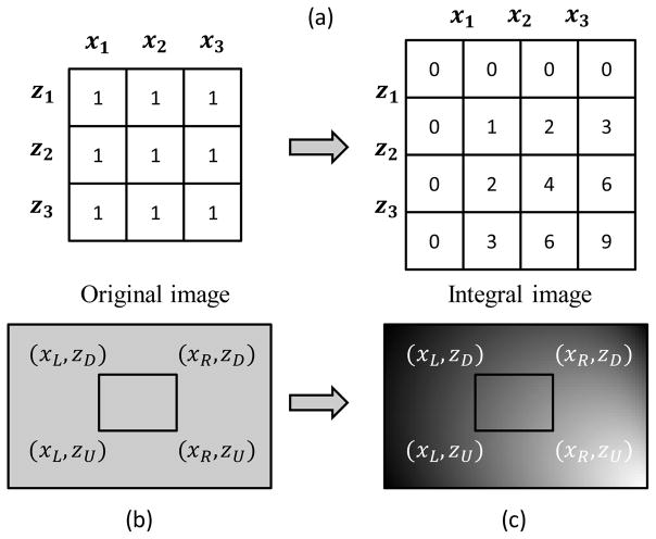
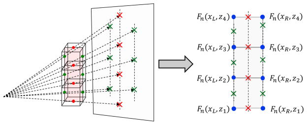
Fig. 3(a) shows how the integral image is generated.
Fig. 3.
Computing the integral over a rectangle region using the integral image. (a) how integral image is generated where x1, x2, x3 and z1, z2, z3 are coordinates of the image pixels. Calculating the integral over the rectangle region in (b) is the same as fetching four integral values at four corners in (c) by applying Eq. (23).
S.2. Interpolation
Given the source position p⃗s and the detector cell position (p⃗L, p⃗R, p⃗U and p⃗D in Fig. 2(b)), the x-ray path cone can be determined. Then, the integral image set will be selected. For each integral image in the set, a rectangle area can be determined by four intersection points between the x-ray cone and the integral plane according to Eq. (10) and Eq. (11) (see Fig. 2(b)). Therefore, four integral values at the rectangle corners marked with golden dots in Fig. 2(b) can be calculated.
S.3. Differentiation
The 2D integral of each slice of the volumetric image can be calculated by Eq. (23) (see Fig. 3(b) and (c)). This avoids to traversal all pixels inside this rectangle as in Eq. (17). The projection is to accumulate all reweighted 2D integrals in the selected integral image set as Eq. (24). The reweighting factors are the intersection area (calculated by multiplying the intersection length lLn and intersection lHn) and the voxel volume size Δv divided by the x-ray path slope.
D. CUDA implementation of Branchless DD Model
We implement the branchless DD projection in CUDA (referred as GPU-BL). In our parallel implementation, one thread calculates one detector cell value in one angle. The calculation of the integral image sets is accomplished in GPU. For each slice of the volumetric image along sagittal/coronal direction, the pixels are accumulated along vertical direction and then accumulated along horizontal direction in order (see Fig. 3(a)). Two integral image sets are mapped to the texture object for high cache and hardware based interpolation mechanism. In the interpolation step, we need to fetch texels on each slice of the integral image. Because the image pixel indices for the intersections xL, xR, zD, zU are not always integers, the values on F(x,z) or F(y,z) at the corner have to be estimated by interpolation. Since f(x,y,z) is piecewise constant, each slice of the integral image set along horizontal or vertical directions is piecewise linear. Therefore, the values on F(x,z) or F(y,z) can be evaluated by bilinear interpolation which is achieved automatically by hardware based interpolation in texture memory.
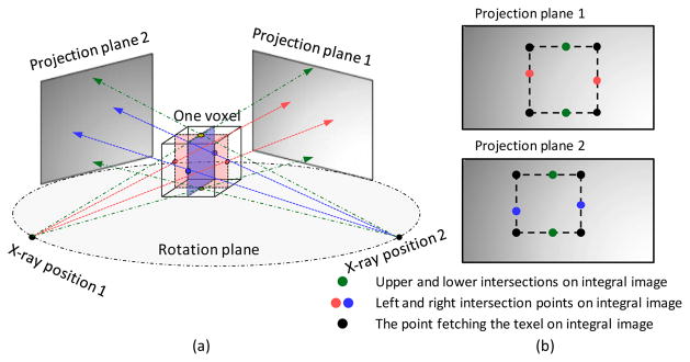
The 3D branchless DD backprojection is calculated in a similar way. In our implementation, one thread calculates one voxel backprojection value. The calculation of the integral image set is performed on every projection data as in Fig. 3(a) which is also performed in GPU. The integral image set is then mapped to the texture object. For a given voxel, we select its middle plane along sagittal or coronal direction for each projection view (Fig. 4(a)) to compute backprojection. Four intersections on the detector are determined by connecting the x-ray source with four middle points on the edges of the middle plane. A rectangle region can be determined as in Fig. 4(b). The integral values at the corner of the rectangle area are fetched and the 2D DD value is calculated by Eq. (23). The backprojection value is the accumulation of all reweighted 2D DD values on every integral image of the projection data.
Fig. 4.
Branchless DD backprojection of one voxel. (a) the selections of different center planes is determined by current projection view angle, (b) the corresponding projection plane 1 and plane 2 with respect to different center planes. The texels are fetched at the black dots on the integral images.
The proposed GPU-BL was also extended to multiple GPUs. Different GPUs were configured in our workstation. With different number of cores and clock rates in these GPUs, the tasks need to be unevenly distributed. To simplify the problem, we did not consider the device memory capacity. The computational power of each GPU is estimated by multiplying the number of CUDA cores and the core clocks. Then, the task scales are tuned manually based on the NVIDIA Profiler software to balance the time consuming for all GPUs for one specific P/BP configuration. Multiple GPUs P/BP is accomplished with OpenMP+CUDA where OpenMP is used to distribute the tasks to GPUs.
E. Precision of hardware interpolation and calculation of integral images
To utilize Eq. (23) for branchless operation, the integral image sets are mapped to the texture memory for hardware based interpolation. However, the texture memory does not represent texel position in IEEE 754 standard but in a 9-bit fixed point value according to the NVIDIA documentation [52]. One bit represents the sign. Although the inaccuracy of using fixed point values to represent interpolation positions may not cause any visual difference in computer graphics applications, the impact of the precision loss in general purpose computing remains an open question. The calculation of the integral image involves summing numbers with very large dynamic ranges and may result in precision loss if it is performed with single-precision floating-point datatype. Although subtracting the DC component can be applied to reduce dynamic range, it cannot completely solve the problem. Both the hardware based texture interpolation and huge dynamic range will cause the inaccuracy.
F. Branchless DD based on double-precision software interpolation (GPU-DB)
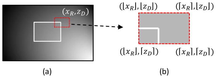
To mitigate the potential precision loss due to GPU hardware fixed-point interpolation and the calculation of the integral image, we also develop a branchless DD implementation based on a software double-precision interpolation (referred as GPU-DB). After determining the rectangle area as in Fig. 2(b), for every corner of the rectangle, the integral values of its four nearest integer index neighbors are fetched and interpolated to calculate the value at that corner as in Fig. 5.
Fig. 5.
Software interpolation based branchless DD. (a) directly fetch the integral value at (xR, zD). (b) fetch the integral values at the positions calculate from integer indices around (xR, zD) and the integral value is calculated by bilinear interpolation.
Both the projection and volumetric images are stored in double-precision floating-point datatype. However, the NVIDIA GPU does not support double-precision floating-point texture. The double-precision floating-point number is casted as a structure composed with two integral numbers and bound to the texture. In the kernel function, the structure composed with two integrals can be casted and interpolated. This method can avoid the inaccuracy caused by the hardware interpolation and integral image limitations. However, because of 4 times texture fetching, slow software interpolation and inefficient GPU computing in double-precision floating-point number, the proposed method is much slower than the original branchless DD method. The speedup performance is only comparable with multi-threads CPU implementation. The pseudocode for GPU-DB and GPU-BL projection and backprojection are integrated together and provided as supplement in Alg. 1 and Alg. 2, respectively.
G. Z-line Backprojection (GPU-BZ)
In our implementation, both the volume and the projection data are stored in an order of priority on the Z-direction. For backprojection, a column of continuously stored voxels shares the same middle plane. Every middle plane of the voxel indicates four texture accesses. Adjacent voxels share edges resulting in redundant texture accesses as illustrated in Fig. 6. For example, in the conventional branchless DD, to calculate the backprojection of a column of three voxels, totally 12 texture accesses and 9 +/− operations are required as
Fig. 6.
Illustration of Z-line based branchless DD backprojection.
| (26) |
where vj, vj+1 and vj+2 are three backprojeciton values of the adjacent voxels along Z-direction from one view angle, and Fn means the integral image of the nth view of the projection data. We can see that there are totally 4 redundant texture fetchings. In Z-line backprojection, the calculation of Eq. (26) is decomposed into two steps. The first step is to fetch the texels and calculate the differences along transverse plane
| (27) |
The second step is to calculate results by subtracting adjacent differences along Z-direction
| (28) |
Therefore, the total texture accesses is reduced to 8 times and the +/− operations are reduced to 7 times. This implementation strategy in the backprojection is referred to as GPU-BZ.
We can see that the intermediate values wj have to be stored during the calculation. In our implementation, wj is stored in shared memory. We calculate backprojection values of one column voxels in one thread. Therefore, if the dimension of the image volume is Nz, it requires Nz+1 space to store the intermediate values. If we assign M threads in one block, there will be M · (Nz+1) shared memory allocated. Because the shared memory is very limited, we cannot assign too many threads in one block. However, if M is not large enough, the warp occupancy of the SM will be low. Therefore, we need to choose M carefully. On the other hand, if the dimension of the image volume Nz is large, we cannot directly allocate the shared memory as required but allocate M · NS shared memory, where NS is the size of the shared memory allocated for one thread. The backprojection values of one column will be calculated in ⌈(Nz+1)/NS⌉ groups sequentially.
Different from backprojection, the projection requires to allocate much more shared memory to calculate the projections of one column detector cells. It is too difficult to limit the usage of the shared memory while guarantee high warp occupancy in the SM simultaneously. Therefore, we will not implement GPU-BZ for projection in this paper. The pseudocode of GPU-BZ backprojection is provided as supplement Alg. 3.
IV. Results
A. Experimental Configuration
The GPUs used in our experiments were GM200 (NVIDIA GeForce Titan X), GK104s (NVIDIA Tesla K10) and NVIDIA GeForce GTX 670. The GM200 contains 3072 cores with a core clock of 1.0GHz and the device memory is 12GB with a 336.5 GB/sec bandwidth. While for Tesla K10, two GK104 GPUs are configured. Each GK104 contains 1536 CUDA cores with a core clock 745MHz and the device memory is totally 8GB with a 320GB/sec bandwidth. For GTX 670, the GK104 GPU contains 1344 cores with a core clock 915MHz and the device memory is 2GB with a 192GB/s bandwidth.
Two Intel Xeon CPUs are configured and each CPU contains 8 physical cores (16 logical cores in hyper-threading) with a 3.1GHz core clock. The proposed methods are implemented in GPU with CUDA 7.5 runtime API. The CPU reference DD is implemented in ANSI C routine. POSIX threads are used to parallelize the CPU implementation. To evaluate the speedup and accuracy performance, single module evaluations, numerical simulations and image reconstructions from clinical applications are performed.
B. Forward and Back-projector as Single Modules
The speed of GPU-BL was compared with several DD implementations including single-thread CPU DD (referred as CPU-1), 8-threads CPU DD (referred as CPU-8), 32-threads CPU DD (referred as CPU-32), GPU-BS, GPU-DB, and GPU-BZ (only for backprojection). The comparison was based on the GE CT750 HD scanner. The configuration of this geometry is summarized as in Table I.
TABLE I.
The Configuration of GE CT750 HD Geometry
| Parameters | Value |
|---|---|
| Source-to-iso-center distance | 541mm |
| Source-to-detector distance | 949mm |
| In-plane detector cell size | 1.0239mm |
| Cross-plane detector cell size | 1.0963mm |
| Number of detector columns | 888 |
| Number of detector rows | 64 |
| Reconstruction FOV | 500 × 500mm2 |
| Detector offset | (−1.28,0)mm |
1) Speedup Ratios
The P/BP speedup ratios of different DD implementation are summarized in Table II.
TABLE II.
Running time of projection and backprojection (unit: s) in GE CT750 HD geometry.
| Projection(s) | Backprojection (s) | |
|---|---|---|
| CPU-1 | 195.59(1.00x) | 195.44(1.00x) |
| CPU-8 | 24.10(8.12x) | 24.89(7.85x) |
| CPU-32 | 11.48(17.04x) | 11.48(17.02x) |
| GPU-BL | 1.42(137.74x) | 1.04(187.92x) |
| GPU-BS | 2.77(57.61x) | 3.02(64.72x) |
| GPU-DB | 13.46(14.53x) | 17.68(11.05x) |
| GPU-BZ | N/A | 1.21(161.52x) |
The speedups are calculated with respect to CPU-1. Both projection and backprojection achieved about 8-fold accelerations in CPU-8 which agrees well with the number of threads used. The hyper-threading technique of the Intel Xeon CPU provided slightly greater acceleration than 8-fold because the number of physical cores was larger than the number of threads. However, this improvement was only 5% to 15%. Therefore, 32-threads implementation only achieved about 17-fold acceleration with 16 physical cores. The GPU-BL projection achieved 137-fold acceleration, and the GPU-BL backprojection achieved almost 188-fold accelerations. We can also observe that the GPU-BL forward projection was slower than GPU-BL backprojection. This was because two integral image sets were calculated before projection and only one integral image set was calculated before backprojection. The computing costs of integral image sets for P/BP are the same in GPU-BL, GPU-DB, and GPU-BZ. They are 1.1% (15.62ms) of the total projection time and 2.8% (29.12ms) of the total backprojection time, respectively. The computing time for integral image sets in forward projection only depends to the volumetric image size, and the computing time for integral image sets in backprojection only depends on the projection size.
The GPU-BS requires about double time of GPU-BL in projection while about triple time of GPU-BL in backprojection. This is caused by the branches divergence and the nested dual for-loops in the kernel function to traverse all voxels inside the rectangle area defined in Eq. (17). In backprojection, both GPU-BL and GPU-BS requires loop to traversal all views. However, GPU-BL calculates the integral values in the rectangle area with a complexity 0(1). The efficiency of if-else instructions in GPU dramatically depends on the GPU architecture. With the same configuration, GPU-BS spent about 40 seconds and 45 seconds for projection and backprojection respectively in Tesla K10 (Kepler architecture). However, the time costs are much shorter in Titan X (Maxwell architecture) collected in Table II. This is because Maxwell architecture outperforms Kepler architecture in branch divergence. Maxwell architecture improved the control logic partitioning, workload balancing, and instruction scheduling, etc.
The GPU-DB projection performed a little bit worse than CPU-32. As what we have mentioned, the GPU-DB required 4 times more texture memory accesses compared to the GPU-BL and the texel position calculation was achieved by software interpolation instead of the hardware interpolation. Meanwhile, the gaming oriented GeForce Titan X is not optimized for double-precision floating-point arithmetic. Meanwhile, the GPU-BZ did not outperform GPU-BL for backprojection, either. A separate experiment will be performed to further analyze this phenomenon in detail later.
We further analyzed the kernel functions of GPU-BL by the CUDA Visual Profiler version 7.5. With the CT geometry described in Table I, the projection kernel took 1.016 seconds while the backprojection kernel took 0.807 second. The SMs in both projection and backprojection are fully utilized. The performance of P/BP kernel was mainly limited by the memory bandwidth. Except for the kernel functions in P/BP, generating integral image sets also occupied a large portion of the computational time. In our implementation, the integral images were first generated along the horizontal direction, and then along the vertical direction slice by slice. It approximately occupied 0.13 seconds and 0.15 seconds for the projection and backprojection, respectively. About 0.4 seconds was required for the P/BP to transfer the data from/to the host memory. We listed the corresponding giga updates per second (GUPS) that is independent of the problem size in the first order approximation. The giga updates is the total number of ray or voxel updates divided by 10243. According to the GUPS calculation formula in [53],
| (29) |
where the detector cell number is set to 512×512, the image size is set to 5123 and the number of views is 360. In this configuration, the GUPS of several competitive methods are listed in Table III. The GUPS results are consistent with the speedup performance in Table II.
TABLE III.
GUPS of Projection and Backprojection.
| CPU-32 | GPU-BL | GPU-BS | GPU-DB | GPU-BZ | |
|---|---|---|---|---|---|
| Projection | 1.57 | 17.65 | 5.25 | 1.34 | N/A |
| Backprojection | 1.49 | 17.93 | 6.05 | 0.86 | 16.58 |
2) Speed with Respect to Number of Views
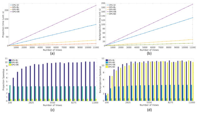
Fixing the image size and the detector size, the speedup performances of GPU-BL was also evaluated by increasing the number of views from 100 to 11,000. In our implementation, we did not use asynchronous technique to hide the data transfer latency. The CPU-1 and CPU-8 were not tested here because of their low speeds. The P/BP time and speedup ratios with respect to CPU-32 are shown in Fig. 7. We can see the time for projection and backprojection almost linearly increased with respect to the number of views. When the number of views was small, the speedup was low because of the overhead for data transfer between CPU and GPU. When the number of views increased, the relative overhead of data transfer became small compared to the computation time on GPU, and the benefit of GPU acceleration dominates. The speedup factor was up to 10× for projection and 11× for backprojection. With more views, the speedup gradually increased and reached a constant. For GPU-BS, the speedup of P/BP almost keeps the same, because its implementation is the parallelization of the CPU version. We can also see that GPU-DB is much slower than other methods.
Fig. 7.
Speedup performance with respect to view number. (a) and (b) are the projection and backprojection computational costs with respect to different view numbers. (c) and (d) are the corresponding speedups compared to CPU-32.
3) Speed with Respect to Image Size In-Plane
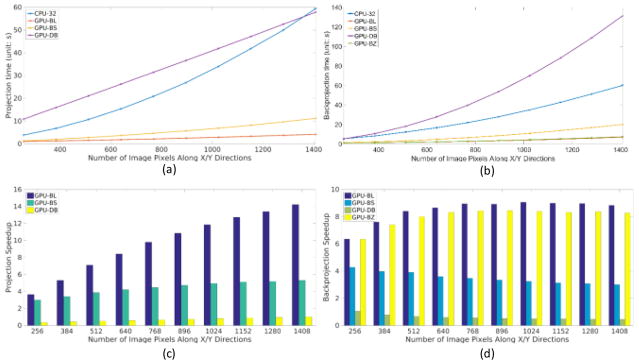
The speeds of different P/BP implementations were evaluated with respect to different image sizes in-plane. With the numbers of views and detector columns fixed, we increased the image size from 2562 to 14082 with a step size of 128 pixels along both X and Y directions. The CPU-32 was also used as the reference to calculate the speedups. The P/BP time and speedups are shown in Fig. 8. We can see that the computational time of CPU-32 in both projection and backprojection increased approximately as a quadratic function which was consistent with the computational scale. However, the computational time of projection with GPU-BL and GPU-DB increased approximately linearly. In branchless DD projection, both the size and the number of integral images increases linearly with in-plane image size, thus the computational complexity of the integration step is quadratic with respect to the in-plane image size. However, the complexity of both the interpolation and differentiation steps is constant for each integral image slice and the computational time of these two steps scales linearly with the number of image slices. Since the computational time of branchless DD projection is dominated by the interpolation and differentiation steps, its overall complexity is approximately linear with respect to in-plane image size within practical configurations. For the above reasons, although the GPU-DB was slower compared to the CPU-32 when the image volume was small, the computational complexity of GPU-DB was lower than CPU-32. From the speedup charts, with the increase of image size, we can see that the projection speedup of GPU-BL is greater for larger in-plane image sizes. When the number of pixels in-plane is small, the speedup of GPU-BS is comparable to GPU-BL, but the speedup of GPU-BL increases faster than GPU-BS. When the image size is up to 14082 in plane, the speedup of GPU-BS almost approaches to its limit. However, we can also observe that the computational time of backprojection with GPU-BL, GPU-BS and GPU-BZ increased approximately quadratically. This is because one thread calculates the backprojection value of one voxel in GPU-BL and GPU-BS or one column of voxels along the Z direction in our GPU-BZ. When the projection data size is fixed and the image size increases quadratically, the amount of computational load also increase quadratically. The speedup of GPU-BS backprojection is slightly decreasing when the in-plane image size increases.
Fig. 8.
Speedup performance with respect to image size along transverse plane. (a) and (b) are the projection and backprojection computational costs with respect to different image size along in-plane direction. (c) and (d) are the corresponding speedups compared to CPU-32.
4) Speed with Respect to Image and Detector along Z-direction
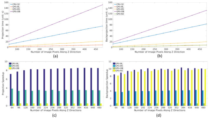
The speed of different P/BP implementations were also evaluated with respect to image and detector sizes along the Z-direction. The image and detector sizes in Z-direction were increased simultaneously from 64 to 480 with a step size of 32. We also applied the CPU-32 as the baseline to calculate the speedup ratio. As shown in Fig. 9, the computational time of projection and backprojection both linearly increased with respect to the numbers of pixels and detector cells along the Z-direction. This linear increase in computation time was consistent with all DD implementations. The sizes of image and detector cell along Z-direction did not affect the speedup ratio.
Fig. 9.
Speedup performance with respect to image and detector sizes along Z-direction. (a) and (b) are the projection and backprojection computational costs with respect to image/detector size along the cross-plane direction. (c) and (d) are the corresponding speedups compared to CPU-32.
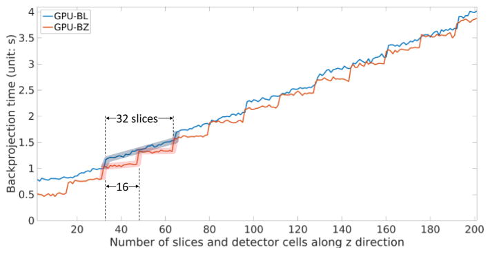
From the previous experiments, one can see that the GPU-BL outperformed GPU-BZ. This is due to severe data latency caused by too much shared memory allocation to store wj. Inadequate threads for each block reduce the warp occupancy resulting in a large portion of cores idle in the streaming multiprocessor (SM). In fact, it is very difficult to balance the SM occupancy and data latency. We evaluated the speedup performances of backprojection with GPU-BL and GPU-BZ by simultaneously increasing the number of pixels and the detector cells along Z-direction. The time profiles are shown in Fig. 10. We can see that the GPU-BZ outperforms GPU-BL when the number of slices and the detector cells along z direction is not large. The time profile of GPU-BZ shows an obvious stair-liked increasing pattern and the stair width is 16 slices. The stair jumps at integer multiples of 16. In our implementation, we allocate Ns = 17 for every thread. Therefore, each time, the backprojection values of 16 voxels will be calculated. For every 16 slices, one more loop will be added in GPU-BZ to perform Eq. (27) and Eq. (28) but calculate only one slice of the voxel. At this time, the speedup will be worse than GPU-BL. If we allocate Ns = 32 + 1 for every thread to calculate 32 voxel values simultaneously, the number of thread of each block M has to be reduced to avoid too much shared memory allocation. However, this will reduce the occupancy of the SM. The time profile of GPU-BL also shows a stair-liked increasing pattern but this pattern is not as obvious as in GPU-BZ. Its stair width is 32 slices. CUDA runs every 32 threads in the SM. This is why the stair width of GPU-BL is 32. In every 32 threads, when more voxels need to be backprojected, the number of memory writing will also linearly increase with more texture memory fetching. Therefore, the time of GPU-BL profile increases linearly in every 32 slices.
Fig. 10.
Backprojection time performances of GPU-BL and GPU-BZ for different number of slices and detector cells along z direction.
5) Accuracy as individual modules
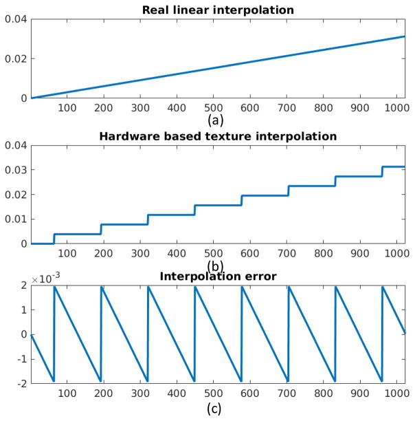
As the aforementioned, the texture memory represents the texels and their positions with 9-bits fixed floating point (eight bits for fractional representation and one bit for sign). Therefore, the position distinction can be only 1/29–1 between two neighborhood texels. We evenly fetched 32,768 = 215 points between two neighborhood texels with values zero and one by texture interpolation. The first 1024 values are depicted in Fig. 11 (b). The interpolated profile is not a straight line from zero to one but a staircase (Fig. 11 (b)). The step width is 128 = 27 = 215–8 pixels which show that the texel position distinction is determined by 8-bits fractional representation. The differences between the exact linear interpolation results and the hardware based texture interpolation are plotted in Fig. 11 (c), We can see that the difference is controlled in 1/29 ≈ 0.2%.
Fig. 11.
Illustration of interpolation errors. (a) The real linear interpolation. (b) The texture fetching based hardware interpolation. (c) The interpolation error between (a) and (b).
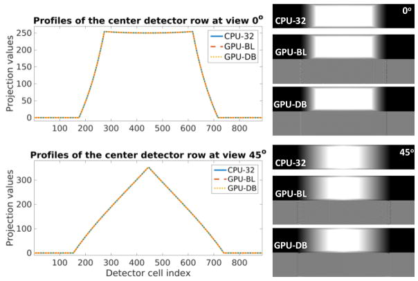
Because GPU-BZ utilizes the shared memory to reduce the texture fetching times during the calculation of GPU-BL, there are no differences in accuracy between GPU-BL and GPU-BZ. Because GPU-BS is a simple parallelization of CPU implementation, the accuracy of GPU-BS and CPU-32 are identical. Therefore, we evaluated the accuracies of the GPU-BL and GPU-DB compared to CPU-32. In GE HD750 CT geometry, an all-one volumetric image is projected. The results from 0 and 45 degrees are shown in Fig. 12. The differences between CPU-32 and GPU-BL are hardly visible unless shown with a very narrow display window. The differences can be further reduced with GPU-DB except at the edge. In this test, the RMSE of GPU-BL projection is 2.77 × 10⁻² and the RMSE of GPU-DB projection is 3.50 × 10⁻⁴.
Fig. 12.
Projection accuracy comparison. The left profiles are the center detector row at 0 degree and 45 for CPU-32, GPU-BL and GPU-DB projections on the right in a display window [0, 250]. The normalized differences between GPU-BL/GPU-DB and CPU-32 are shown below their projections in a display window [−0.002, 0.002].
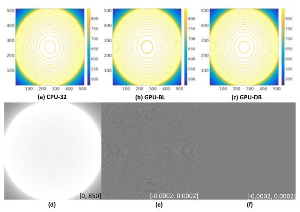
In the same geometry, a projection with value 1.0 at view angle 0 was backprojected. The contours from CPU-32, GPU-BL and GPU-DB were shown in Fig. 13 (a) (b) and (c), respectively. From the center slice of the volumetric image, we can see that the contours of GPU-BL are not as smooth as those in CPU-32 and GPU-DB. The contours of CPU-32 and GPU-DB are visually identical. Fig. 13(d) shows the central slice of the volumetric image backprojected from GPU-BL. In a greater display window, the results are smooth and they are not as rough as the contours in Fig. 13 (b). The normalized differences between CPU-32 and GPU-BL are given in Fig. 13(e) in a narrow display window. We can observe some regular patterns caused by the inaccuracy of hardware-based interpolation. For GPU-DB, the differences in the same display window can be hardly observed (Fig. 13 (f)). Then, we backprojected 984 views to the volumetric image. The same comparisons are collected in Fig. 14. The roughness of the contours in GPU-BL is weaker. The normalized differences are much weaker than in one view. We showed the normalized differences in a much narrower display window in [−0.0002, 0.0002]. With GPU-DB, the ring disappears. In this case, the RMSE of GPU-BL backprojection is 5.24 × 10⁻² and the RMSE of GPU-DB projection is 6.92 × 10⁻⁴.
Fig. 13.
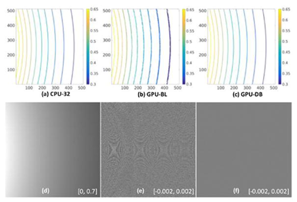
Backprojection accuracy comparison for one view. (a), (b) and (c) are contours of the center slice of the volumetric image backprojected from one view with value 1.0 by CPU-32, GPU-BL, and GPU-DB, respectively. (d) is the central slice of the volumetric image backprojected from GPU-BL. (e) is the normalized difference between CPU-32 and GPU-BL, and (f) is the normalized difference between CPU-32 and GPU-DB.
Fig. 14.
Backprojection accuracy comparison for 984 views. (a), (b) and (c) are contours of the center slice of the image volume backprojected from 984 views with value one by CPU-32, GPU-BL, and GPU-DB respectively. (d) is the center slice of the image volume backprojection result from GPU-BL. (e) is the normalized difference between CPU-32 and GPU-BL, and (f) is the normalized difference between CPU-32 and GPU-DB.
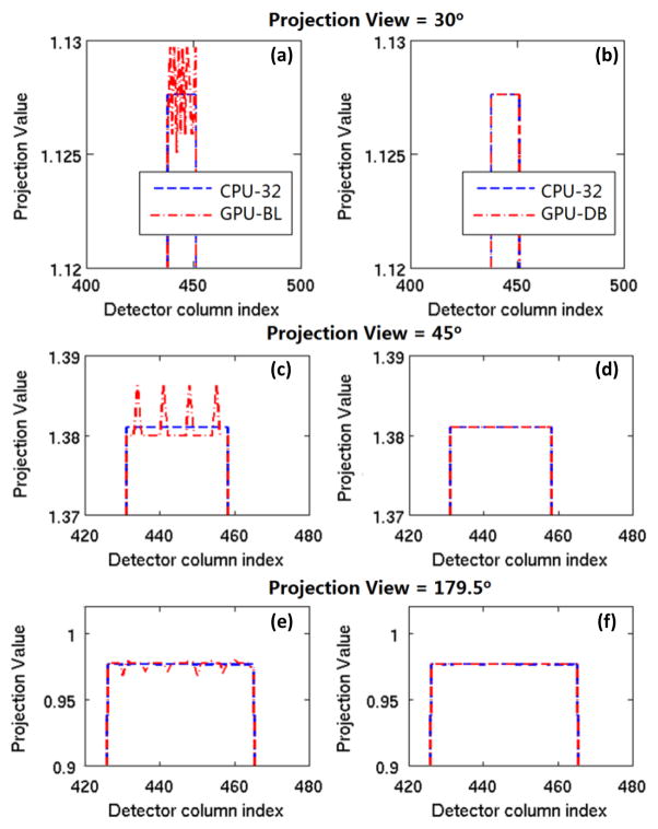
To quantify the relative errors of the GPU-BL and demonstrate the merits of GPU-DB in accuracy improvement, a 25 × 1 pixels bar (value = 1.0) on x-axis, whose central pixel index is 12, was projected onto the detector in parallel geometry for several view angles. We set the pixel size to 1.00mm. The detector size in channel direction is 1.41mm while the detector cell size in bench moving direction is 0.71mm. When the projection view is 0, the GPU-BL and CPU implementations are still the same. We plotted the projections of 30, 45, and 179.5 degrees in Fig. 15. Because of the inaccurate expression of the value for fast hardware-based interpolation in texture memory, the projection errors in GPU-BL can be observed in a magnified display window. The relative error is smaller than 0.2% in Fig. 15 (a). Using the software based interpolation, the spur liked error can significantly suppressed. Therefore, the GPU-DB is useful for applications that require high accuracy.
Fig. 15.
Projection accuracy comparison between GPU-BL and GPU-DB at different view angles for a uniform bar. The red dash lines in (a), (c), and (e) are the projection profiles for GPU-BL, and the red dash line in (b), (d), and (f) are the projection profiles for GPU-DB.
6) Multi-GPUs Branchless DD
The performance of multi-GPUs-BL is summarized in Table IV. We show the total times, kernel times, and computing times for integral image sets. The Multiple GPUs computation cannot provide much higher speedups compared to single GPU when the number of views was small. The GPUs with weaker computational power had lower bandwidth which made the data transfer more time consuming. Furthermore, the calculation of integral images also occupied appreciable computational cost. Although more GPUs were employed, the total cost to compute the integral images did not decrease. When the number of views was large, the P/BP time was reduced significantly.
TABLE IV.
Computational costs (in seconds) of various components on multiple GPUs. The image volume is 512 × 512 × 64 with (a) 984, (b) 1968 and (c) 3936 views of size 888 × 64 in HD geometry.
| (A) 984 Views | ||||
|---|---|---|---|---|
| Number of GPUs | 1 | 2 | 3 | 4 |
| Projection | 1.478 | 1.107 | 1.102 | 1.101 |
| Projection Kernel | 1.009 | 0.703 | 0.579 | 0.457 |
| Integral image set (P) | 0.016 | 0.012 | 0.010 | 0.010 |
| Backprojection | 1.041 | 0.953 | 0.944 | 0.886 |
| Backprojection Kernel | 0.618 | 0.454 | 0.346 | 0.272 |
| Integral image set (BP) | 0.029 | 0.026 | 0.026 | 0.024 |
|
| ||||
| (B) 1968 Views | ||||
|
| ||||
| Number of GPUs | 1 | 2 | 3 | 4 |
| Projection | 2.550 | 2.045 | 1.762 | 1.581 |
| Projection Kernel | 2.012 | 1.411 | 1.184 | 0.897 |
| Integral image set (P) | 0.033 | 0.028 | 0.025 | 0.021 |
| Backprojection | 1.933 | 1.504 | 1.351 | 1.261 |
| Backprojection Kernel | 1.260 | 0.832 | 0.703 | 0.552 |
| Integral image set (BP) | 0.059 | 0.054 | 0.053 | 0.048 |
|
| ||||
| (C) 3936 Views | ||||
|
| ||||
| Number of GPUs | 1 | 2 | 3 | 4 |
| Projection | 4.685 | 3.513 | 2.841 | 2.542 |
| Projection Kernel | 4.029 | 2.853 | 2.305 | 1.791 |
| Integral image set (P) | 0.069 | 0.058 | 0.055 | 0.052 |
| Backprojection | 3.579 | 2.754 | 2.253 | 1.842 |
| Backprojection Kernel | 2.693 | 1.746 | 1.461 | 1.174 |
| Integral image set (BP) | 0.125 | 0.120 | 0.117 | 0.113 |
C. Iterative Reconstruction
1) Simulation data
Noiseless numerical simulations were conducted to investigate the performance of GPU-BL for IRAs. In our numerical simulations, a monochromatic x-ray cone-beam CT with equal-angular detector was assumed. A modified Shepp-Logan phantom and a FORBILD head phantom were employed, and the image sizes are 512×512×64. The full scan projection datasets were evenly acquired with 2200 views on a circular scanning trajectory. A ray-tracing model was applied to simulate the projection in size 3552×256. Then for each view, every 4×4 neighboring detector cells were averaged to form the 888×64 projection. The linear attenuation coefficients of the two phantoms were reconstructed by an OS-SART algorithm with the proposed GPU-BL projector. The final results were compared with the ground truth and CPU-32 based OS-SART results. The number of ordered subsets was 10. The maximum iteration number was 40.
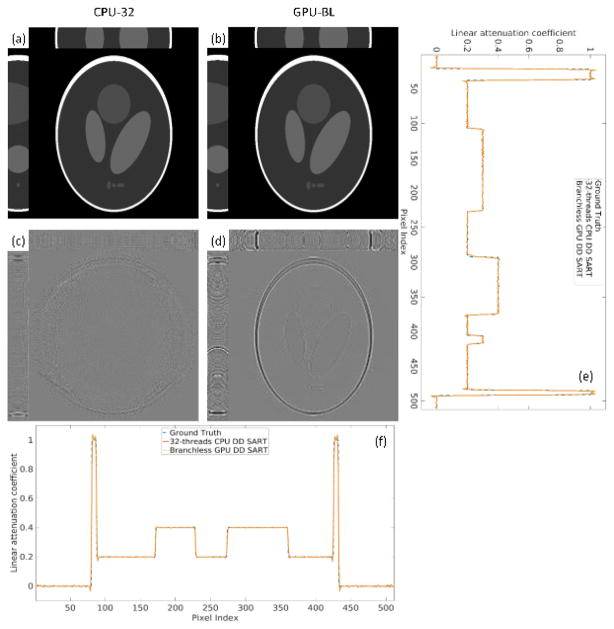
The reconstructed modified Shepp-Logan from CPU-32 and GPU-BL are shown in Fig. 16(a) and (b), respectively. The difference between CPU-32 and GPU-BL, and between CPU-32 and the ground truth are shown in Fig. 16(c) and (d), respectively, in a much narrower display window, and the representative profiles along horizontal and vertical directions of the center transverse plane are shown in (e) and (f). We can see that the reconstruction errors are greater at the top and bottom slices. This is because the top and bottom slices cannot be completely irradiated in circular cone-beam geometry. From (e) and (f), we can see that the profiles match the ground truth very well except some Gibbs artifact at the edges of the object, usually seen in numerical simulations with piece-wise constant objects.
Fig. 16.
Numerical simulation results of the modified Shepp-Logan phantom. (a) are the transverse, sagittal and coronal planes reconstructed by the CPU-32 in a display window [0, 1]. (b) are the counterpart of (a) reconstructed by the GPU-BL. (c) is the error between CPU-32 and GPU-BL in display window [−0.001, 0.001]. (d) is the corresponding error of ground truth and GPU-BL in display window [−0.02 0.02]. (e) and (f) are the horizontal and vertical profiles of the center slice of the images.
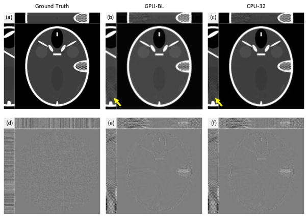
The reconstructed FORBILD head images in transverse, sagittal and coronal planes are shown in Fig. 17(b) and (c) in a display window[1.0, 1.2]. The corresponding reconstruction errors in a narrower window are shown in (e) and (f). As indicated by the arrows in (b) and (c), the reconstruction errors can be observed in sagittal and coronal planes from both GPU-BL and CPU-32. As aforementioned, the mismatch between GPU-BL and CPU-32 is about 0.2% (see Fig. 17(d)). The computation time per iteration of FORBILD head phantom reconstruction are summarized in Table V. We can see that the acceleration rate of GPU-BL is significant. Although GPU-BS is also faster than CPU-32, the computing times for P/BP are 2 to 3 times longer than those of GPU-BL. The kernel times of GPU-BS are closer to the total time than GPU-BL because there are no integration steps in GPU-BS.
Fig. 17.
Numerical simulation results of the FORBID head phantom. (a) is the ground truth. (b) and (c) are the reconstruction results from GPU-BL and CPU-32, respectively. The display window for on the first row images is [1.0,1.2]. (d) is the differences between (b) and (c) in a display window [−0.005,0.005]. (e) and (f) are the reconstruction errors of (b) and (c) with respect to (a) in a display window [−0.02,0.02].
TABLE V.
Speedup performance of the FORBILD head phantom reconstruction in one iteration.
| Unit: second | Projection | Backprojection | ||
|---|---|---|---|---|
|
| ||||
| CPU-32 | 24.13 | 26.63 | ||
|
| ||||
| GPU-BL | TOTAL | KERNEL | TOTAL | KERNEL |
| 2.75 | 2.25 | 2.78 | 1.92 | |
|
| ||||
| GPU-BS | 5.89 | 5.65 | 8.07 | 7.82 |
2) Real Phantom Reconstruction
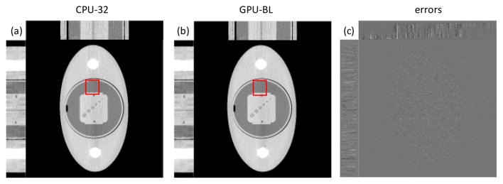
We also acquired real phantom data from a GE Discovery CT750 HD system (GE Healthcare, Waukesha, WI) with 888 detector channels and 984 views per rotation. We scanned an oval-shaped phantom with a quality-assurance insert and two Teflon rods on both sides. The data were acquired with a 32-row helical scan with a pitch of 31/32 at 120 kVp, 835 mA, and 1 second rotation. Images were reconstructed on a grid of 512×512×64 with a field-of-view of 50 cm, an in-plane pixel size of 0.98 mm, and a slice thickness of 0.625 mm. All reconstructions used q-GGMRF regularization [54] and weighted-least-squares data-fit term. All reconstructions were based on 100 iterations of a preconditioned conjugate gradient algorithm initialized with standard FBP images [55]. The reconstruction is presented in Fig. 18. The differences between Fig. 18(a) and (b) are hardly noticeable unless displayed within a much narrower window in Fig. 18(c). The RMSE of GPU-BL with respect to CPU-32 was 0.57 HU. The differences between Fig. 18(a) and (b) are almost imperceptible, although there is very small difference inside the red rectangle under very careful comparison.
Fig. 18.
Real phantom reconstruction results. (a) and (b) are reconstructed by the CPU-32 and GPU-BL from high dose (835mAs) projections in a display window [800 1200]HU. (c) is the difference image between CPU-32 and GPU-BL for low dose case in a display window [−3, 5]HU.
3) Clinical Application
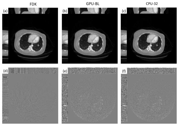
Finally, with the approval of Wake Forest University School of Medicine, a clinical patient dataset was used to evaluate the GPU-BL. The dataset was acquired for cardiac imaging of coronary artery in high-resolution model with focal spot deflection, with 2,200 views, 120kVp, and 300mA. The volumetric image was reconstructed by the SART algorithm in the same geometry as in Table. 1. Because the dose is relatively high, we did not employ any regularization term, and FDK was implemented as a reference. A 512×512×64 volumetric image was reconstructed. We used the Titan X to perform our experiments. 300 SART iterations were run and the FISTA technique [56] was also applied for acceleration. The FDK reconstruction was also provided as a reference in Fig. 19(a). After 300 iterations, the reconstruction results from GPU-BL and CPU-32 are shown in Fig. 19(b) and (c), respectively. The differences between GPU-BL and CPU-32 are shown in Fig. 19(d) in a narrow display window [−0.5, 0.5] HU. The differences relative to the FDK reconstruction are displayed in Fig. 19(e) and (f) in a window of [−20, 20] HU. One can also see the greater difference at the top and bottom slices of the reconstructed volumetric image. The SSIM [57] of the central slice of GPU-BL result relative to the FDK reconstruction is 0.9905.
Fig. 19.
Reconstructed results from a clinical data set. (a) is reconstructed by the FDK algorithm as a reference. (b) and (c) are reconstructed by the GPU-BL CPU-32, respectively. (d) is the differences between GPU-BL and CPU-32 in a display widow [−0.5, 0.5] HU. (e) and (f) are the differences between the FDK reference and GPU-BL and CPU-32 in display window [−20, 20] HU, respectively.
V. Discussions and Conclusions
In this paper, we implemented a branchless DD P/BP algorithm for 3D cone beam CT. The developed algorithm eliminated the irregular branch behavior of the original DD algorithm and made the DD operation highly amenable to massive vectorization of GPUs. For a GE Discovery CT750 HD system, the proposed method achieved 137-fold speedup for projection and 188-fold speedup for backprojection compared to a single thread CPU implementation. Compared to a state-of-the-art 32-thread CPU implementation, the proposed branchless DD P/BP achieved 8-fold acceleration for forward projection and 10-fold acceleration for backprojection. Different branchless DD implementations (GPU-BL, GPU-BS, GPU-DB and GPU-BZ) compromise between the speedup performance and accuracy. Our implementation of branchless DD also fully leveraged the cache mechanism and the hardware interpolation supported by the texture memory in GPUs.
For the multi-GPU implementation, we showed the speedup with different types of GPUs. The tasks were distributed according to the computational power of different GPUs. Manually tuning is required to achieve best balance and utilization for each GPU. It is still an open problem on how to automatically distribute the tasks to heterogeneous GPUs to achieve best performance.
We evaluated our branchless DD methods with extensive numerical simulation, physical simulation and real clinical dataset. Some loss of precision of the branchless algorithm can be caused by the integration and interpolation steps when implemented with single-precision data type and hardware based interpolation. The errors are approximately controlled in 0.2% which is about 1/29. Because NVIDIA texture memory applied 9 bits to represent one floating number address. However, our reconstruction results from simulation and real data showed that the precision loss was small and the GPU-based branchless algorithm obtained visually identical images as the CPU reference algorithm.
This study focused on algorithm development and the GPU implementation was not fully optimized. In particular, the integration step of branchless DD occupied a considerable portion of the computational time. However, highly optimized GPU algorithms [58] exist for computing the integral of 2D images and can be readily incorporated for further acceleration. Although our implementation has not been fully optimized, its speedup performance is better than [12] for backprojection. Our implementation of iterative reconstruction involved repeated data transfer between GPU device memory and CPU host memory. Some standard GPU programming techniques can be used in the future to reduce or hide this data transfer latency. The overhead of data transfer could also be eliminated by implementing the entire iterative reconstruction in GPUs.
Acknowledgments
The work was initally an internship project at the Image Reconstruction Lab at GE Global Research. This work was partially supported by the NSF CAREER Award 1540898 and NIH/NIBIB grant EB017140. The authors would like to thank Evgeny Drapkin, Ryan Thome, and Debashish Pal at GE Healthcare for helpful discussion, and Masako Yamada and Kang Zhang in the Advanced Computing Lab at GE Global Research for providing computing resources and helpful discussion.
Contributor Information
Rui Liu, Wake Forest University Health Sciences, Winston-Salem, NC 27103 USA.
Lin Fu, General Electric Global Research, 1 Research Cycle, Niskayuna, NY 12309 USA.
Bruno De Man, General Electric Global Research, 1 Research Cycle, Niskayuna, NY 12309 USA.
Hengyong Yu, Department of Electrical and Computer Engineering, University of Massachusetts Lowell, Lowell, MA 01854 USA.
References
- 1.Chen B, Ning R. Cone-beam volume CT breast imaging: Feasibility study. Medical physics. 2002;29(5):755–770. doi: 10.1118/1.1461843. [DOI] [PubMed] [Google Scholar]
- 2.Popovtzer R, et al. Targeted gold nanoparticles enable molecular CT imaging of cancer. Nano letters. 2008;8(12):4593–4596. doi: 10.1021/nl8029114. [DOI] [PMC free article] [PubMed] [Google Scholar]
- 3.Rabin O, Perez JM, Grimm J, Wojtkiewicz G, Weissleder R. An X-ray computed tomography imaging agent based on long-circulating bismuth sulphide nanoparticles. Nature materials. 2006;5(2):118–122. doi: 10.1038/nmat1571. [DOI] [PubMed] [Google Scholar]
- 4.Hanke R, Fuchs T, Uhlmann N. X-ray based methods for non-destructive testing and material characterization. Nuclear Instruments and Methods in Physics Research Section A: Accelerators, Spectrometers, Detectors and Associated Equipment. 2008;591(1):14–18. doi: 10.1016/j.nima.2008.03.072. [DOI] [PMC free article] [PubMed] [Google Scholar]
- 5.Man BD, Nuyts J, Dupont P, Marchal G, Suetens P. Metal streak artifacts in X-ray computed tomography: a simulation study. IEEE Transactions on Nuclear Science. 1999 Jun;46(3):691–696. [Google Scholar]
- 6.De Man B. Iterative reconstruction for reduction of metal artifacts in computed tomography. University of Leuven; 2001. [Google Scholar]
- 7.Liu R, Yu H. CUDA based Spectral CT simulation. presented at the 2015 BMES Annual Meeting; 2015. [Google Scholar]
- 8.De Man B, Basu S. Distance-driven projection and backprojection. 2002 IEEE Nuclear Science Symposium Conference Record; 2002. pp. 1477–1480. [Google Scholar]
- 9.Man BD, Basu S. Distance-driven projection and backprojection in three dimensions. Physics in Medicine and Biology. 2004 Jun;49(11):2463–2475. doi: 10.1088/0031-9155/49/11/024. [DOI] [PubMed] [Google Scholar]
- 10.Basu S, De Man B. Branchless distance driven projection and backprojection. presented at the SPIE; 2006. pp. 60650Y–60650Y–8. [Google Scholar]
- 11.Liu R, Fu L, De Man B, Yu H. GPU Acceleration of Branchless Distance Driven Projection and Backprojection. presented at the 4th International Conference on Image Formation in X-Ray Computed Tomography; Bamberg, Germany. 2016. [Google Scholar]
- 12.Schlifske D, Medeiros H. A fast GPU-based approach to branchless distance-driven projection and back-projection in cone beam CT. 2016;9783:97832W-97832W–8. [Google Scholar]
- 13.Mitra A, Degirmenci S, Politte DG, O’Sullivan JA. Fast Parallel GPU Implementation for Clinical Helical CT using Branchless DD. presented at the GPU Technology Conference; 2016. p. 6234. [Google Scholar]
- 14.Herman GT. Fundamentals of Computerized Tomography. London: Springer London; 2009. [Google Scholar]
- 15.Siddon RL. Fast calculation of the exact radiological path for a three-dimensional CT array. Medical Physics. 1985 Mar;12(2):252–255. doi: 10.1118/1.595715. [DOI] [PubMed] [Google Scholar]
- 16.Zhuang W, Gopal SS, Hebert TJ. Numerical evaluation of methods for computing tomographic projections. IEEE Transactions on Nuclear Science. 1994 Aug;41(4):1660–1665. [Google Scholar]
- 17.Zeng GL, Gullberg GT. A Ray-driven Backprojector For Backprojection Filtering And Filtered Backprojection Algorithms. Nuclear Science Symposium and Medical Imaging Conference, 1993., 1993 IEEE Conference Record; 1993. pp. 1199–1201. [Google Scholar]
- 18.Joseph PM. An Improved Algorithm for Reprojecting Rays through Pixel Images. IEEE Trans Med Imaging. 1982;1(3):192–196. doi: 10.1109/TMI.1982.4307572. [DOI] [PubMed] [Google Scholar]
- 19.Liu R, Luo Y, Yu H. GPU-Based Acceleration for Interior Tomography. IEEE Access. 2014;2:757–770. [Google Scholar]
- 20.EPMC [Accessed: 20-Apr-2016];Backprojection for x-ray CT system - Patent - Europe PMC. [Online]. Available: http://europepmc.org/patents/PAT/US5473654.
- 21.Peters TM. Algorithms for Fast Back- and Re-Projection in Computed Tomography. IEEE Transactions on Nuclear Science. 1981 Aug;28(4):3641–3647. [Google Scholar]
- 22.Zwicker M, Pfister H, van Baar J, Gross M. EWA Splatting. IEEE Transactions on Visualization and Computer Graphics. 2002 Jul;8(3):223–238. [Google Scholar]
- 23.Fessler JA. Penalized weighted least-squares image reconstruction for positron emission tomography. IEEE Trans Med Imaging. 1994;13(2):290–300. doi: 10.1109/42.293921. [DOI] [PubMed] [Google Scholar]
- 24.Liu R, He L, Luo Y, Yu H. 2D Singular Value Decomposition based Interior Tomography. presented at the The 13th International Meeting on Fully Three-Dimensional Image Reconstruction in Radiology and Nuclear Medicine; Newport, Rhode Island, USA. 2015. [Google Scholar]
- 25.Liu R, He L, Luo Y, Yu H. Singular value decomposition-based 2D image reconstruction for computed tomography. Journal of X-ray Science and Technology. doi: 10.3233/XST-16173. [DOI] [PubMed] [Google Scholar]
- 26.Cho ZH, Chen CM, Lee S. Incremental algorithm-a new fast backprojection scheme for parallel beam geometries. IEEE Trans Med Imaging. 1990;9(2):207–217. doi: 10.1109/42.56333. [DOI] [PubMed] [Google Scholar]
- 27.Yu DC, Huang SC. Study of reprojection methods in terms of their resolution loss and sampling errors. Conference Record of the 1992 IEEE Nuclear Science Symposium and Medical Imaging Conference; 1992; 1992. pp. 1160–1162. [Google Scholar]
- 28.Lewitt RM. Alternatives to voxels for image representation in iterative reconstruction algorithms. Phys Med Biol. 1992 Mar;37(3):705–716. doi: 10.1088/0031-9155/37/3/015. [DOI] [PubMed] [Google Scholar]
- 29.Byonocore MH, Brody WR, Macovski A. A Natural Pixel Decomposition for Two-Dimensional Image Reconstruction. IEEE Transactions on Biomedical Engineering. 1981 Feb;BME-28(2):69–78. doi: 10.1109/TBME.1981.324781. [DOI] [PubMed] [Google Scholar]
- 30.Hsieh J, Molthen RC, Dawson CA, Johnson RH. An iterative approach to the beam hardening correction in cone beam CT. Medical Physics. 2000 Jan;27(1):23–29. doi: 10.1118/1.598853. [DOI] [PubMed] [Google Scholar]
- 31.Yu H, Wang G. Finite detector based projection model for high spatial resolution. J Xray Sci Technol. 2012;20(2):229–238. doi: 10.3233/XST-2012-0331. [DOI] [PMC free article] [PubMed] [Google Scholar]
- 32.Sutherland IE, Hodgman GW. Reentrant polygon clipping. Communications of the ACM. 1974 Jan;17(1):32–42. [Google Scholar]
- 33.Triangulation D, Lee DT, Schachter BJ. Two Algorithms for Constructing a Delaunay Triangulation. 1978 [Google Scholar]
- 34.Long Y, Fessler J, Balter JM, et al. 3D forward and back-projection for X-ray CT using separable footprints. Medical Imaging, IEEE Transactions on. 2010;29(11):1839–1850. doi: 10.1109/TMI.2010.2050898. [DOI] [PMC free article] [PubMed] [Google Scholar]
- 35.Li X, Ni J, Wang G. Parallel iterative cone beam CT image reconstruction on a PC cluster. Journal of X-Ray Science and Technology. 2005;13(2):63–72. [Google Scholar]
- 36.Li J, Papachristou C, Shekhar R. An FPGA-based computing platform for real-time 3D medical imaging and its application to cone-beam CT reconstruction. Journal of Imaging Science and Technology. 2005;49(3):237–245. [Google Scholar]
- 37.Xue X, Cheryauka A, Tubbs D. Acceleration of fluoro-CT reconstruction for a mobile C-arm on GPU and FPGA hardware: a simulation study. Proc SPIE. 2006;6142:1494–501. [Google Scholar]
- 38.Professional CUDA C Programming. 1. Indianapolis, IN: Wrox; 2014. [Google Scholar]
- 39.Gaster B, Howes L, Kaeli DR, Mistry P, Schaa D. Heterogeneous Computing with OpenCL, Second Edition: Revised OpenCL 1.2 Edition. 2. Waltham, MA: Morgan Kaufmann; 2012. [Google Scholar]
- 40.Scherl H, Keck B, Kowarschik M, Hornegger J. Fast GPU-Based CT Reconstruction using the Common Unified Device Architecture (CUDA). IEEE Nuclear Science Symposium Conference Record, 2007. NSS ’07; 2007. pp. 4464–4466. [Google Scholar]
- 41.Mueller K, Yagel R, Wheller JJ. A Fast and Accurate Projection Algorithm for 3D Cone-Beam Reconstruction with the Algebraic Reconstruction Technique (ART) [Google Scholar]
- 42.Cabral B, Cam N, Foran J. Accelerated Volume Rendering and Tomographic Reconstruction Using Texture Mapping Hardware. Proceedings of the 1994 Symposium on Volume Visualization; New York, NY, USA. 1994. pp. 91–98. [Google Scholar]
- 43.Okitsu Y, Ino F, Hagihara K. High-performance cone beam reconstruction using CUDA compatible GPUs. Parallel Computing. 2010 Feb;36(2–3):129–141. [Google Scholar]
- 44.Kachelriess M, Knaup M, Bockenbach O. Hyperfast parallel-beam and cone-beam backprojection using the cell general purpose hardware. Med Phys. 2007 Apr;34(4):1474–1486. doi: 10.1118/1.2710328. [DOI] [PubMed] [Google Scholar]
- 45.Rohkohl C, Keck B, Hofmann HG, Hornegger J. Technical Note: RabbitCT—an open platform for benchmarking 3D cone-beam reconstruction algorithms. Medical Physics. 2009;36(9):3940. doi: 10.1118/1.3180956. [DOI] [PubMed] [Google Scholar]
- 46.Mueller K, Yagel R. Rapid 3-D cone-beam reconstruction with the simultaneous algebraic reconstruction technique (SART) using 2-D texture mapping hardware. IEEE Trans Med Imaging. 2000 Dec;19(12):1227–1237. doi: 10.1109/42.897815. [DOI] [PubMed] [Google Scholar]
- 47.Xu F, Mueller K. Accelerating popular tomographic reconstruction algorithms on commodity PC graphics hardware. IEEE Transactions on Nuclear Science. 2005 Jun;52(3):654–663. [Google Scholar]
- 48.Xu F, Mueller K. Real-time 3D computed tomographic reconstruction using commodity graphics hardware. Physics in Medicine and Biology. 2007;52(12):3405. doi: 10.1088/0031-9155/52/12/006. [DOI] [PubMed] [Google Scholar]
- 49.Mueller K, Xu F, Neophytou N. Why do commodity graphics hardware boards (GPUs) work so well for acceleration of computed tomography? SPIE Electronic Imaging. 2007;6498:64980N. [Google Scholar]
- 50.Xu F, et al. On the efficiency of iterative ordered subset reconstruction algorithms for acceleration on GPUs. Computer methods and programs in biomedicine. 2010;98(3):261. doi: 10.1016/j.cmpb.2009.09.003. [DOI] [PMC free article] [PubMed] [Google Scholar]
- 51.Jang B, Kaeli D, Do S, Pien H. Multi GPU implementation of iterative tomographic reconstruction algorithms. IEEE International Symposium on Biomedical Imaging: From Nano to Macro, 2009. ISBI ’09; 2009. pp. 185–188. [Google Scholar]
- 52. [Accessed: 04-May-2016];CUDA Toolkit Documentation. [Online]. Available: http://docs.nvidia.com/cuda/#axzz47h6lb3uY.
- 53.Chou CY, Chuo YY, Hung Y, Wang W. A fast forward projection using multithreads for multirays on GPUs in medical image reconstruction. Med Phys. 2011 Jul;38(7):4052–4065. doi: 10.1118/1.3591994. [DOI] [PubMed] [Google Scholar]
- 54.Thibault JB, Sauer KD, Bouman CA, Hsieh J. A three-dimensional statistical approach to improved image quality for multislice helical CT. Med Phys. 2007 Nov;34(11):4526–4544. doi: 10.1118/1.2789499. [DOI] [PubMed] [Google Scholar]
- 55.Fu L, et al. A preliminary investigation of 3D preconditioned conjugate gradient reconstruction for cone-beam CT. 2012;8313:83133O-83133O–9. [Google Scholar]
- 56.Beck A, Teboulle M. A Fast Iterative Shrinkage-Thresholding Algorithm for Linear Inverse Problems. SIAM J Imaging Sci. 2009 Jan;2(1):183–202. [Google Scholar]
- 57.Wang Z, Bovik AC, Sheikh HR, Simoncelli EP. Image quality assessment: from error visibility to structural similarity. IEEE Transactions on Image Processing. 2004 Apr;13(4):600–612. doi: 10.1109/tip.2003.819861. [DOI] [PubMed] [Google Scholar]
- 58.Hensley J, Scheuermann T, Coombe G, Singh M, Lastra A. Fast Summed-Area Table Generation and its Applications. Computer Graphics Forum. 2005;24(3):547–555. [Google Scholar]


