Abstract
Alginate microgels are widely generated by ionic crosslinking methods, but this method has limitations in controlling the microgel degradation and generating non-spherical microgels. By employing oxidized methacrylated alginate (OMA) that is degradable and photocrosslinkable, we have successfully photocrosslinked monodisperse OMA microgels and demonstrated the feasibility to generate discoid alginate microgels. However, several technical issues obstructed our opto-microfluidic method from being a useful technique. Here, we further characterized and optimized this method. Monodisperse discoid OMA microgels with good shape consistency were, for the first time, generated. The curability of OMA microgels was characterized as the macromer concentration varied from 2% to 10%, and the minimum required photoinitiator (VA-086) concentrations were determined. The effects of crosslinking density and the presence of ions in the storage solution on swelling of OMA hydrogels were identified to give insights into accurate controlling of the microgel size. A much quicker degradation rate (within three weeks) compared to ionically crosslinked alginate hydrogels was indirectly identified by quantifying the elastic modulus using atomic force microscopy. The viability of encapsulated chondrocytes in OMA microgels formed by this method was higher than those from other existing methods, demonstrating its favorable cytocompatibility. It was found that the oxygen tension played a critical role in both the curability of microgels and the cytocompatibility of this technique. We also summarize common practical issues and provide related solutions and/or operational suggestions. By this method, OMA microgels are expected to be valuable alternatives to traditional ionically crosslinked alginate microgels in drug delivery, tissue engineering, and single cell analysis areas due to their multiple favorable properties.
I. INTRODUCTION
Microgels are microscale polymerized (also frequently referred to as “cured” or “crosslinked”) hydrogels. Alginate is one of the most extensively employed materials to generate microgels for numerous applications, such as drug delivery,1 cell encapsulation/tissue engineering,2 and disease diagnostics,3 due to its mild crosslinking process, good biocompatibility, biomimetic micro-/nanostructure, and high water content.4 Various microfluidic approaches have been devised to improve alginate microgel manufacturing in terms of monodispersity,5 production efficiency,6 biocompatibility,7 and system robustness.8 These methods typically utilized ionic crosslinking to fabricate spherical microgels. There are several drawbacks using this ionic crosslinking mechanism, including slow and uncontrollable degradation rate of alginate9 and practical difficulty in generating non-spherical shaped microgels with monodispersity and shape consistency.10 These disadvantages limit the biomedical applications of alginate microgels, such as in disease diagnostics, drug delivery, and tissue engineering. For example, in tissue engineering, it is important for the scaffolds to degrade at a similar rate as new tissue formation.11 However, the degradation of ionically crosslinked alginate is unpredictable and uncontrollable.9 In addition, the non-spherical shapes of microgels have various advantages, such as evading immune clearance and controlling zero-order drug release.12 We have utilized biodegradable oxidized methacrylated alginate (OMA) to solve the degradation issue.13 Recently, by taking advantage of the photocrosslinked OMA, we employed the in-situ photocrosslinking microfluidic methodology to devise a microfluidic system to generate photocrosslinked monodisperse OMA microgels under ultraviolet (UV) light.14 We have demonstrated the simplicity of the photocrosslinking method compared to the existing ionic crosslinking method to generate non-spherical OMA microgels.
However, several key unknowns (or technical issues) prevented this prototype method from becoming a viable technique. First, OMA microdroplets were often uncured in-situ, and so, the monodispersity and the non-spherical shape of microgels were often compromised or unachieved.14 There were multiple crosslinking parameters that affect the OMA microgel curability, such as macromer and photoinitiator (P.I) concentrations, UV exposure time (microchannel length), and UV intensity. Note that these parameters were also related to other common microgel manufacturing issues, such as scattered UV light-induced clogging in polydimethylsiloxane (PDMS) microchannels15 and back pressure-induced leakage of plasma bonding in a long microchannel.5 In addition, because the OMA macromer concentration is an important parameter to regulate the mechanical properties, degradation rates, and permeability of OMA microgels,13 the minimum photoinitiator concentration to cure OMA microgels at various macromer concentrations was unknown. Second, photocrosslinked OMA microgels would swell after collecting them in a water-based solution, which compromised the dimensional accuracy of microgels and accelerated degradation (preliminary data not shown). However, how to reduce the swelling was still a challenge. Third, although theoretically the OMA microgels will degrade according to the degradation rate of bulk OMA hydrogels, the actual degradation characteristics of OMA microgels were not previously demonstrated.14 This was because unlike bulk hydrogels whose degradation rate is often quantified by mass loss, measuring mass was impractical for microgels. Last, the cytocompatibility of this microfluidic photocrosslinking process was not demonstrated. Without answering these questions, this method was still underdeveloped and the advantages of OMA over traditional alginate could not be employed for microgels.
In this report, we fill these knowledge gaps to further refine this method and present many important practical suggestions to utilize this technique. First, the curability of OMA microgels at various macromer concentrations was investigated and the threshold of photoinitiator (VA-086) concentration (minimum required concentration) was determined. Second, swelling behavior of the OMA microgels was studied and several key factors (photoinitiator concentration, UV light exposure duration, and presence of ions in the storage solution) were identified to understand how to control microgel dimensions. Third, atomic force microscopy (AFM) was employed to test the mechanical property (elastic modulus) of microgels over time to indirectly demonstrate their biodegradability. Finally, the cytocompatibility of this method was demonstrated. Several factors (i.e., presence of oxygen, UV light, and out-of-incubator time for cells) were studied to ensure a high viability of encapsulated human chondrocytes. In this paper, discoid microgels were generated for the curability, swelling, and degradation rate tests to show the advantage of the non-spherical shape of microgels, whereas spherical microgels were used to encapsulate cells for the cytocompatibility test to simplify observation and data analysis. Complemented with such information, our in-situ photocrosslinking microfluidic method can be a reliable and versatile technique to fulfill requirements of different engineering applications. Due to their favorable properties, the OMA microgels are expected to be promising alternatives to traditional ionically crosslinked alginate microgels for tissue engineering, drug delivery, or single cell diagnostics.
II. MATERIALS AND METHODS
A. In-situ photopolymerizing microfluidic system design and manufacture
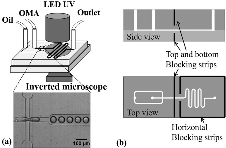
The in-situ photopolymerizing microfluidic system consisted of a polydimethylsiloxane (PDMS) microchip, two syringe pumps (Pump 11 Elite, Harvard Apparatus, MA), a light-emitting diode (LED) UV light (Hamamatsu, Japan), a home-customized microchip holder sealed in a zipped plastic bag (Ziploc vacuum seal food storage bag, Dow, MI), and nitrogen supply [Fig. 1(a)]. The microgel generation process was observed under a phase contrast microscope (Eclipse Ti-U, Nikon, IL), and images were taken using QuantEM 512SC (Photometrics, AZ). Soft lithography was used to manufacture the microchip, and press-fit interconnects were employed for the oil and OMA inlets and the outlet.16,17 The microchip was plasma bonded on a PDMS substrate. A flow-focusing method was used to generate OMA microdroplets,18 where mineral oil (Sigma, MO) complemented with 5 wt. % Span 80 (Sigma, MO) served as the outer continuous phase to shear and pinch the inner disperse OMA phase into monodisperse microdroplets. Following the flow-focusing section was a serpentine downstream channel for UV light exposure to photocrosslink OMA microdroplets into microgels. The length of the serpentine channel varied to control the UV exposure duration, but the entire serpentine section area was exposed under the circular area of UV light (with a diameter of 1 cm). The microchannel height was either 15 μm to generate discoid microgels for the curability, swelling, and degradation tests or 40 μm to generate spherical microgels for the cytocompatibility test. All the microchannel design dimensions are presented in Table I. A filter pattern was used at the two inlets according to the protocol of Mazutis et al. to filter out potential particles that may clog the flow-focusing section.19 In addition, scattered UV light in PDMS can crosslink the OMA at the upstream of the flow focusing section and clog the microchannel. To solve this issue, four slits were made in the PDMS microchip by a blade and aluminum foil strips were inserted inside the slits surrounding the UV exposure section to block the UV light [see Fig. 1(b)].
FIG. 1.
In-situ photocrosslinking microfluidics setup and cell encapsulation at the flow focusing section (a) and aluminum strips embedded in PDMS to block scattered UV (b).
TABLE I.
Dimensions of microchannels and their usage.
| Height (μm) | Focusing orifice width (μm) | Serpentine channel length (cm) | Usage |
|---|---|---|---|
| 15 | 40 | 2, 3, 4, 6, 9 | Discoid microgel manufacturing, Swelling test, Curability test, and Degradation test |
| 40 | 40 | 6 | Cell encapsulation and viability test |
B. Monodisperse and discoid microgel generation and dimensional characterization
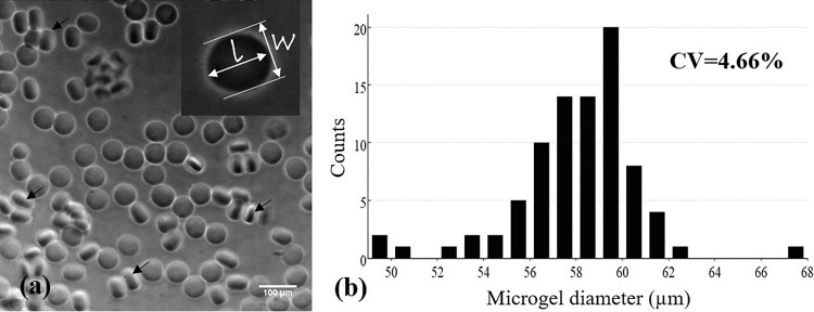
OMA with actual 14% oxidation degree and 20% methacrylation degree (measured by 1H-nuclear magnetic resonance spectroscopy) was synthesized,13 dissolved (at 10 wt. %) in calcium-free Dulbecco's phosphate buffered saline (DPBS, Mediatech, VA), and complemented with photoinitiator (VA-086, Wako, at 1 wt. %). Macromer solution was covered by aluminum foil thereafter to prevent UV exposure. To avoid UV exposure, the OMA inlet tubing and outlet tubing were also covered by aluminum foil. Since oxygen (O2) hinders the free radical photocrosslinking reaction,20 the microgel generating process should be under low oxygen tension conditions.14 To remove O2, the microchip was degassed in a vacuum chamber (Robinair 15600, MI) more than 2–3 h before use, and the microfluidic setup was stored in a customized plastic bag with a zipper filled with nitrogen while generating microgels. The two phases of flows were driven into the microchannel by two syringe pumps, and their flow rates were tuned until the monodisperse microdroplets were generated steadily. The microdroplets were at least one diameter away from each other to avoid coalescence. Then, the LED UV light was applied at 30% power setting (intensity of ∼250 mW/cm2) or lower to prevent scattered UV light-induced OMA clogging in the microchannel. The generated OMA microgels were washed, collected in DPBS, and measured using microscopy and ImageJ (National Institute of Health). Specifically, “elliptical selections” in ImageJ were employed to manually measure the perimeter and shape descriptors of the microgels. The diameter was back calculated from the perimeter. Hence, monodispersity of discoid microgels was determined by quantifying the coefficient of variation (standard deviation of diameter/average diameter) of the diameter of the microgels. The roundness (shape consistency) of the microgels was characterized by aspect ratio (shape descriptors) that is defined as a length ratio of major axis to minor axis [Fig. 2(a)].
FIG. 2.
(a) Monodisperse discoid OMA microgels with good shape consistency (average aspect ratio of 1.048 ± 0.036) and (b) size distribution of one representative sample (coefficient of variation = 4.66%). The flow rates of oil and OMA solution phases were 60 and 30 μl/h, respectively. The diameter of microgels was calculated by the measured perimeters of microgels using ImageJ. Black arrows indicate the examples of microgels positioned on their side edge.
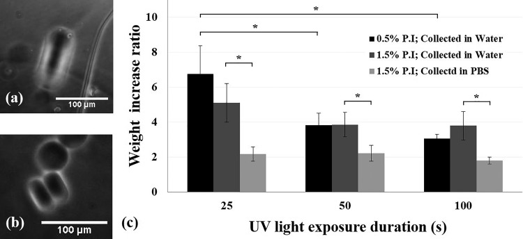
The size of OMA microgels could be accurately quantified and controlled in situ, but they would swell (by absorbing water) after collection in a water-based solution, which highly compromised their dimensional accuracy and even degradation rate. Therefore, it is necessary to quantify the swelling ratio of microgel to microdroplet and to reduce the swelling (water absorbency). First, discoid microgels were generated by a 15 μm high microchannel and collected in deionized (DI) water or DPBS, separately. Since the height of the microchannel was more accurate (also constant) than the microgel diameter, we used the thickness of discoid microgels, instead of the diameter, to describe their linear (one-dimensional) swelling. After collection, the thickness of microgels that positioned on their side edge was measured (see the black arrows in Fig. 2). Second, to further test how crosslinking density and ions in the collecting/storage solution affected the swelling, 8% OMA macrogels were made with 0.5% or 1.5% VA-086, along with UV light exposure for 25, 50, or 100 s, and stored in DI water or DPBS at room temperature for one day. The weight increase ratio, defined as the weight of swollen gel divided by the original weight of wet gel, was measured.
C. Characterization of microgel curability
The 15 μm high microchannels were used to test the curability of OMA microgels. OMA-DPBS solutions (at 2, 4, 6, 8, and 10 wt. %) complemented with various photoinitiator concentrations (from 0.5 to 3 wt. %) were individually tested to identify whether the discoid microdroplets could be cured by 30% power setting UV light (∼250 mW/cm2) for 30 s. The microgels were defined as cured when their discoid shape was preserved after they flowed inside the outlet under microscopy observation. If microgels coalesced inside the microchannel or deformed back to the spherical shape in the outlet due to surface tension, they were considered uncured.
D. Characterization of the change in elastic modulus of microgels over time
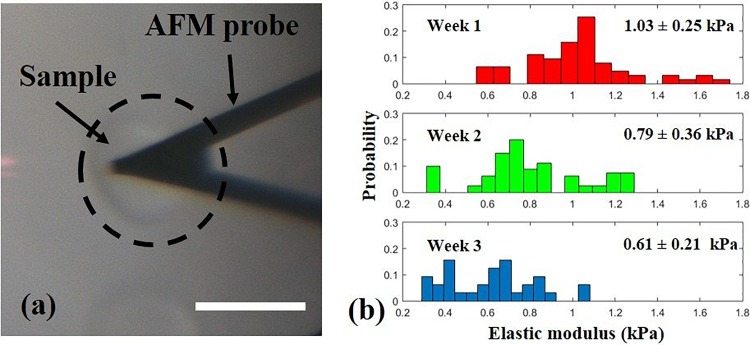
We have previously reported on the influence of different macromer concentrations on the OMA macrogel degradation rate by measuring mass loss.13 However, it was difficult to measure the mass of microgels. Therefore, AFM was employed to test a mechanical property (i.e., elastic modulus) of the microgels to indirectly characterize their degradation over time. To prevent microgels from rolling during AFM experiments, we used discoid shaped microgels. The discoid microgels (8 wt. % OMA in DPBS with 1.5 wt. % VA-086) were photocrosslinked by 15% power setting UV light (∼125 mW/cm2) for ∼30 s exposure and were incubated in DPBS at 37 °C with 5% CO2 for three weeks. The DPBS was changed every week. The elastic modulus of the microgels was measured in weeks 1, 2, and 3 by using a Bruker Dimension ICON (Bruker, CA) complemented with MSNL-C cantilevers with a nominal force constant of 0.010 N/m (Bruker, CA) as force sensors. The actual cantilever force constants were calibrated as 0.011 ± 0.002 N/m using the thermal noise method.21–23 The cantilevers were lowered onto the microgels until 1 nN contact force was reached and then retracted while the force-displacement curves were recorded. Ten microgels were measured for each test, and ten force curves were recorded for each microgel. The Sneddon conical indenter model was employed to analyze the elastic moduli of the microgels due to the much larger indentation compared to the cantilever tip size.24
E. Chondrocyte encapsulation and viability analysis
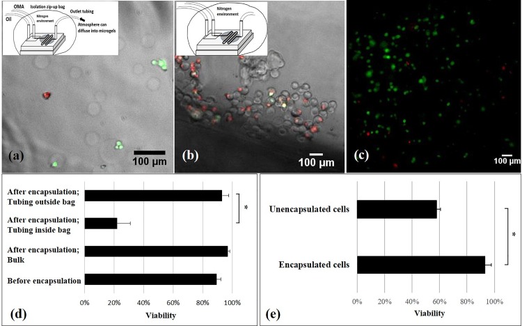
Primary human chondrocytes and culture kits (medium and subculture kits) were purchased from Lonza (Lonza, MD), and the cells were cultured according to the manufacture's protocol.25 Cells with population doublings less than 11 (5 to 6 passages) were suspended at 7 × 10⁶ to 107 cell/ml in OMA solution (10 wt. % OMA and 3 wt. % VA-086 in 80 v/v % DPBS and 20 v/v % OptiPrep). The OptiPrep density matcher (Sigma, MO) increased the density of solution to avoid cell sedimentation and aggregation.19 The cell suspension was degassed for less than 1 min to remove air bubbles if necessary. Brief vacuuming for 2 min did not affect the cell viability significantly (data not shown). Cell-encapsulated microgels were photocrosslinked by 25% power setting UV light (∼200 mW/cm2) for about 30 s exposure. After 30 min of encapsulating cells, the cell-encapsulation sample was washed with DPBS twice and chondrocyte differentiation medium (Lonza, MD) once and cultured in a 24-well plate with 300 μl of chondrocyte differentiation medium (Lonza, MD) at 37 °C with 5% CO2. To test the effects of oxygen tension on cell viability during the encapsulation process, two groups of cell-encapsulation samples were generated in one experiment with all the same encapsulating parameters (UV intensity, exposure duration, OMA and VA-086 concentrations, etc.) except the outlet tubing left inside or outside the isolation bag during the encapsulating process. The viability of cells in the OMA solution was tested by trypan blue using a hemocytometer before the encapsulating process. In addition, after each encapsulation experiment, the leftover cell-OMA sample was cured in bulk hydrogels (∼1 cm diameter and ∼0.5 mm thick disk-shaped sample) by 25% power setting UV light (∼200 mW/cm2) for 30 s. The viability of cells in these three groups (bulk, tubing inside and outside the isolation bag) was quantified on day 1 by LIVE/DEAD assay (Molecular Probes, Inc., OR). On average, 75 cells were analyzed in the tubing-inside group for each experiment, 39 cells in the tubing-outside group, and more than 300 cells in the bulk group.
F. Statistical analysis
The curability experiment and the macrogel swelling experiment were repeated three times (n = 3). The biocompatibility experiment was repeated twice (n = 2). One-way analysis of variance (ANOVA) was used to analyze the data using Microsoft Excel, and statistical significance was accepted at p < 0.05. The results were expressed as mean ± standard deviation. The coefficient of variation (defined as standard deviation divided by mean) of microgel diameters was used to identify their monodispersity.
III. RESULTS AND DISCUSSION
A. Generation of monodisperse discoid microgels with good shape consistency
Discoid OMA microgels with good monodispersity and shape consistency were, for the first time, generated by the photocrosslinking method (Fig. 2). The coefficient of variation of microgel diameter in one representative sample was 4.66%, less than 5%, and so, the microgels were considered monodisperse. The average aspect ratio (a measure of the roundness or shape consistency) of the microgels in a representative sample was 1.048 (±0.036). This shape consistency was much better than that of the discoid alginate microgels using the traditional external ionic crosslinking method, where the crosslinking fluid flow could shear and deform the alginate droplets and the deformation was preserved, resulting in low shape consistency.10 One advanced ionic crosslinking method was reported by inducing divalent cations inside the alginate microdroplets to improve the shape consistency and material homogeneity (i.e., internal ionic crosslinking).26 Our shape consistency result was as good as that reported by this method. The reason is that the OMA microgels were crosslinked without the additional flow, and so, their shape was well maintained. More importantly, the operation of our method to generate discoid alginate microgels was much simpler than the ionic crosslinking method by eliminating one additional flow-focusing configuration (and the usage of two syringe pumps) and especially by avoiding synchronizing the alginate microdroplets with crosslinking droplets.10
B. Curability of OMA microgels
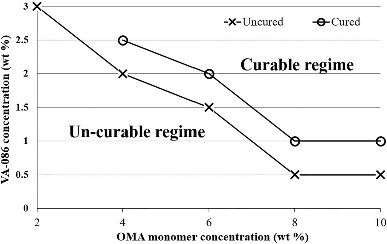
Curability in this system had been a challenge when trying to generate OMA microgels. Generally, a hydrogel is considered cured (or “crosslinked,” “polymerized”) when the storage modulus exceeds the loss modulus during the polymerization process by dynamic rheological tests.27 The state of being cured indicates that the shape of the hydrogel can be preserved in the short term and does not dissolve in water-based solutions. By our method, if the OMA microdroplets were not cured in-situ, their non-spherical shape would not be preserved and they would coalesce or even dissolve in the collecting water-based solution. We now have a better understanding regarding how to cure OMA microgels. First, it was found that as the OMA macromer concentration increased, a lower photoinitiator concentration was required to cure the microgels (Fig. 3). Within our tested range, 2 wt. % OMA microgels could not be cured even when the macromer solution was almost saturated with VA-086 (at 3.5 wt. %). When the OMA macromer was as high as 8% or 10%, only 1% VA-086 was needed to cure the microgels. Second, increasing either UV light intensity or exposure duration could increase the curability of microgels. However, we limited the UV light intensity (lower than 30% power setting, ∼250 mW/cm2) and exposure duration (25 ± 3 s) to generate microgels for two practical reasons. First, although applying UV light at 70% power setting (∼500 mW/cm2) could cure 6% OMA with 1.5% VA-086 microgels, such a high UV intensity resulted in the aforementioned UV light scattering issue. Specifically, the scattered UV light would very quickly partially cure the OMA before entering the flow-focusing section, and so, the OMA phase flowed slower and slower and eventually clogged the flow-focusing section. This was consistent with another group's observation when using the photocrosslinking approach to generate microgels in PDMS microchannels.15 Second, it was true that by elongating the UV exposure duration to 120 s, 8% OMA with 1% VA-086 microgels could be cured by lower intensity UV light (25% power setting, ∼200 mW/cm2). However, achieving such long UV exposure times required extremely low flow rates (1 μl/h for both oil and OMA phases) in the serpentine channels used, which resulted in an unacceptably low microgel production rate. Alternatively, to prolong the UV exposure duration, the serpentine channel needs to be made much longer, but this can result in much higher back pressure and even leakage. Therefore, this curability contour plot only presents material compositions and UV parameters (power setting less than 30% and exposure time less than 30 s) with relatively high robustness and production efficiency, excluding the extreme cases using too high UV light intensity or too long exposure time.
FIG. 3.
Curability contour plot, presenting the minimum concentration of VA-086 required to cure OMA microgels at different macromer concentrations.
Some other factors played key roles in microgel curability. First, it is well known that oxygen negatively affects free radical-initiated polymerization.20 Therefore, we degassed the microchip overnight and used a plastic isolation bag filled with nitrogen to contain the microchip during the microgel manufacturing process. Second, the curability is proportional to the availability of crosslinking domains on the alginate backbone (i.e., the methacrylation degree). We used OMA with 20% actual methacrylation. OMA with a different methacrylation degree will have different characteristics of microgel curability (a different relation between the macromer concentration and the minimum required photoinitiator concentration, UV light intensity, and exposure time). Third, the type of photoinitiator used is critical because different photoinitiators may have different reaction efficiencies.28 The reaction efficiency of VA-086, to our knowledge, has not been studied, but it seemed not to be as efficient as a widely used photoinitiator, Irgacure 2959, based on our qualitative observation on curing OMA gels (data not shown). However, VA-086 was reported to be much more cytocompatible than Irgacure 2959,29 and so, it was chosen for our study to encapsulate cells.
In addition to further understanding how to generate OMA microgels as discussed above, we also demonstrated the efficiency of using non-spherical microgels to test the curability of microgels. It was hard to observe the difference between the cured microgels and uncured ones under a microscope if they were spherical. In this case, to identify their state, the microgels had to be collected into an aqueous solution to identify whether they dissolved. Alternatively, the microgel samples were dried and rehydrated to identify whether they could recover their shape. Both these strategies are inefficient and cumbersome. In this study, we could determine the curability of microgels in-situ under a microscope by taking advantage of the non-spherical microgels. If the microgels did not coalesce inside the microchannel and the flat surfaces (which were confined by the top and bottom of the microchannel) of microgels were observed at the outlet, the microgels were conformed as cured. If the discoid microgels were not fully cured, they would become spherical after entering the outlet due to the surface tension.
C. Characterization of mechanical property changes of microgels over time
To indirectly evaluate the degradation of OMA microgels, elastic modulus changes over time were measured using an AFM.30 The average elastic modulus of OMA microgels (10% OMA, 1% VA-086, cured by ∼250 mW/cm2 UV for 30 s) decreased from 1.03 ± 0.25 kPa, to 0.79 ± 0.36 kPa and to 0.61 ± 0.21 kPa over three weeks (Fig. 4). The decreased moduli of microgels suggests a very quick degradation rate compared to ionically crosslinked alginate.31 The Sneddon conical indenter model was employed to analyze the elastic moduli of the microgels because the indentation depth was much greater than the cantilever tip size.24 In addition to indirectly demonstrating the biodegradability of OMA microgels, we also identified an advantage of using discoid microgels for the AFM tests. When AFM was employed to test spherical samples (such as cells or microgels), a holder was necessary to immobilize the samples.32 Otherwise, the microgel would roll away when the tip touched it. In contrast, the discoid microgels did not roll, and so, the immobilizing holder was eliminated. Since the oxidation and methacrylation degrees and OMA macromer concentration can affect the degradation of hydrogels, further studies are necessary to fully understand how to precisely control the microgel degradation rate in the future.
FIG. 4.
A discoid microgel was tested by AFM without a holder (a) and the elastic modulus of microgels decreased over three weeks (b). Scale bar: 50 μm.
D. Cytocompatibility of the microfluidic photocrosslinking process
We demonstrated that our in-situ photocrosslinking method was cytocompatible to encapsulate chondrocytes in OMA microgels with 93.5 ± 4.5% viability (Fig. 5). More importantly, the cell viability using this method was better than the traditional ionic crosslinking alginate encapsulation methods and a photocrosslinking method using visible light (Table II). Although the photocrosslinking encapsulation method presented a comparable high cell viability (85 ± 2.3%) to ours, this study photocrosslinked the microgels out of the microfluidic device (in a beaker for 5 min), resulting in disperse microgels.33
FIG. 5.
LIVE/DEAD fluorescence images of chondrocytes and viability results. LIVE/DEAD fluorescence image merged with bright-field microscopy images of microgel-encapsulated cells when the end of outlet tubing was kept outside the isolation bag (a) and when the outlet tubing was kept inside the isolation bag (b). LIVE/DEAD fluorescence images of chondrocytes embedded in left-over macrogel after the encapsulation experiment (c). Effects of the oxygen and encapsulation process on cell viability (d): The significant difference between groups where the tubing was left inside and outside of the isolation bag suggests critical effects of oxygen on the cell viability. The non-significant difference of viability between the microgel encapsulated cells and left-over cells in the syringe indicates no negative effects of the microfluidic photocrosslinking process on the cell viability. Note that the viability of cells before the encapsulating process was tested by trypan blue staining. Effects of encapsulation on cell viability (e): Many unencapsulated cells in the collected sample came from the setting up period before applying UV light. These unencapsulated cells had a lower viability than the encapsulated ones, potentially due to the fluid flow shear stress in the microfluidic system or the collision between the microgels and the cells. *p < 0.05. n = 2.
TABLE II.
Viability comparison between different alginate microgel encapsulation methods.
| Methods | Cell type | Test time | Viability | References |
|---|---|---|---|---|
| The present method | Primary human chondrocytes | Day 1 | 93.5 ± 4.5% | – |
| Photocrosslinking by visible light | Cat kidney epithelial cells (CRFK) cells | Day 0 | 85 ± 2.3% | 33 |
| External ironic crosslinking | Primary rabbit chondrocytes | Day 7 | 59 ± 18% | 2 |
| External ironic crosslinking; non-spherical microgels | Colon cancer cells (HCT116) | Day 0 | 50% | 34 |
| Internal ionic crosslinking | Jurkat cells | Day 0 | 19.3% to 74.3%a | 5 |
| Improved internal ionic crosslinking | Antibody-secreting hybridoma cells (9E10) | Day 0 | 84% | 7 |
| Mouse breast cancer cells (M6C) | 86% |
This dataset was not viability, but the percentage of live cells after the process, defined as (Nalive,after/Nalive,before) × 100%, where Nalive,before and Nalive,after referred to the percentage of cells alive before the experiment and the percentage of cells alive after the experiment, i.e., greater than the actual viability. In addition, this value varied greatly depending on the material systems.
To achieve such a high viability, one critical practice was required: the end of collecting outlet tubing should be left outside the isolation bag to avoid oxygen tension to encapsulated cells for a too long time. On the other hand, the short time hypoxia was necessary to ensure free radical-induced polymerization inside the microchannel and did not affect cell viability [Fig. 5(a)]. Our preliminary study showed very low viability of encapsulated cells in microgels [Figs. 5(b) and 5(d)], when the outlet tubing was left inside the isolation bag. Interestingly, when the left-over cell-OMA suspension inside the syringe from the encapsulation experiment was cured by the same UV light intensity and exposure duration as used for microgel encapsulation, the viability of cells was higher than 90% [Figs. 5(c) and 5(d)]. Previous studies also suggested that VA-086 initiated alginate photopolymerization is cytocompatible.29 Hence, we assumed that the low oxygen tension resulted in the cell death, and so, we left the end of outlet tubing out of the isolation bag to let the oxygen in the atmosphere diffuse into the collected microgel-oil mixture. This practice significantly increased the viability. Therefore, based on these results, low oxygen was the only factor that negatively affected the cell viability during the microencapsulation process. Negative effects of long time storage (at least 3 h) in OMA-DPBS solution at room temperature, fluid flow shear stress, UV light exposure, or the presence of free radicals on cell viability were not detected. Note that during the setting-up processes, including adjusting the size and monodispersity of the microdroplets (for 10 to 30 min) and waiting for the steady states of the flows (at least 5 min), the UV light was not applied, and so, the OMA-cell microdroplets were not cured. Hence, there were many unencapsulated chondrocytes in the collected cell-OMA encapsulation samples. The viability of encapsulated cells was significantly higher than the unencapsulated cells on day 1 [Fig. 5(e)]. It might be because of fluid flow shear stress or the collision between the microgels and the cells7 in the microfluidic system and/or the washing process lowered the viability of unencapsulated cells. In contrast, microencapsulation provided a physical protection to the encapsulated cells.
E. Optimization of technical parameters and important identified design parameters
Here, we present some important suggestions for potential users of this technology. To generate monodisperse discoid microgels with required dimensions, the following manufacturing parameters (and practical tips) should be considered. First, the initial distance between the discoid microdroplets right after the flow focusing section should be as long as possible (at least ∼5 times microdroplet diameter) and the length of the serpentine UV exposure section should be appropriate. Generally, the serpentine microchannel should be long enough for sufficient UV light exposure duration but short enough to reduce the possibility of coalescence. In our material system (10% OMA and 1% VA-086), the UV exposure time was insufficient to cure the microgels in the microchip with a 2-cm long serpentine section, whereas coalescence of microgels often occurred at the end of the serpentine channel in the 9-cm long one. Specifically, it was always observed that at the downstream end of the serpentine section, the discoid microgels intermittently stagnated and moved. When stagnated microgels were freed, they collided with microgels further downstream and coalesced into a plug of microgels in a series (Fig. 6). Note that the uncured discoid microdroplets could move together with an initial inter-microgel distance, and so, there was a transitional section during crosslinking, where the distance between the consecutive microdroplets continuously decreased until they collided. Since the top and bottom surfaces of discoid microgels were contacting the microchannel, we attributed the intermittent stagnating and moving motions to friction between the microgels and the microchannel. The 6-cm long serpentine microchannel was the optimal one although 3 and 4-cm ones could generate discoid microgels too. Additionally, the initial distance between droplets was adjusted to be longer than 5 times of the microdroplet diameter to ensure that they could be cured before the collision occurred downstream. Alternatively, the serpentine section can be replaced by a diverging/converging section to slow down the microdroplet movement (to increase the exposure time).15 How to avoid the microdroplet coalescence in such a configuration has been studied.35
FIG. 6.
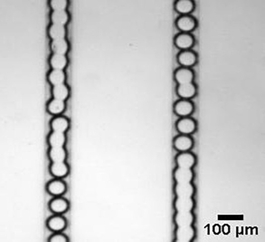
Coalesced microgels inside the microchannel. Although the coalescence was an issue for discoid microgel production, it also implied the possibility to generate the non-spherical microgels in a column.
Second, to precisely control the size of microgels, the swelling of microgels after washing and collection in the aqueous solutions needs to be considered. We observed that the presence of ions in solutions used to wash and collect microgels highly affected their swelling. Microgels swelled approximately fourfold or twofold when they were washed and collected in DI water or DPBS, respectively [Figs. 7(a) and 7(b)]. Similarly, the mass increase ratio of macrogels stored in DI water was significantly greater than that in DPBS after the macrogels reached equilibrium over one day [Fig. 7(c)]. Therefore, to decrease swelling (dimensional change), it is suggested that the microgels were washed and collected in DPBS or cell culture medium. In addition, the macrogel swelling results suggest that crosslinking density affected the swelling [Fig. 7(c)]. By increasing the UV exposure duration to increase the crosslinking density, the macrogels with 0.5% VA-086 could swell significantly less. Since the UV light exposure time was limited in the microchannel, microgels can be post-exposed to UV light to fully cure them before washing in the aqueous solutions.
FIG. 7.
Swollen microgels in DI water (a) and DPBS (b). The thickness of the discoid microgels before the washing process was limited to the height of microchannels (15 μm), and so, linear swelling can be quantified by measuring the microgel thickness after the washing process. Effects of the photoinitiator (P.I) concentration, UV exposure duration, and presence of ions in the storage solution on the weight increase ratio of macrogels (c). Both the UV light exposure duration and the presence of ions (type of washing solution) significantly affected the mass changes of macrogels, which indicated the water absorbency and swelling. *p < 0.05. n = 3.
IV. CONCLUSION
When we reported on this in-situ photocrosslinking strategy to generate OMA microgels,14 multiple technical unknowns remained, such as how to generate monodisperse discoid microgels, the impact of variables in the system on curability and biodegradability of the OMA microgels, and the cytocompatibility of the microfluidic photocrosslinking encapsulation process. These unknowns or technical issues made this method practically unreliable to employ. The present paper filled the knowledge gaps and solved some critical technical issues. We also demonstrated the advantage of using discoid microgels, compared to spherical microgels, to test curability and temporal changes in microgel mechanical properties. We have provided adequate information and necessary practical advice for potential users to use this new technique to generate non-spherical, biodegradable, and monodisperse alginate microgels to encapsulate cells with high viability. The advantageous properties of these microgels make them promising for drug delivery, tissue engineering, and single cell analysis. Particularly, by controlling the microgel shape and degradation rate, microfluidic-based encapsulation in OMA might be to control the microenvironments of cells. For example, it may be possible to maintain the chondrogenic phenotype of chondrocytes and improve the regeneration of pericellular matrix. This can be critical for engineering cartilage tissues and will be our future research focus.
ACKNOWLEDGMENTS
The authors thank Peter G. Shankles and Dr. Scott T. Retterer for fabricating the microfluidic channels at the Center for Nanophase Materials Sciences, Oak Ridge National Laboratory. The authors gratefully acknowledge funding from the Department of Mechanical Engineering-Engineering Mechanics at Michigan Technological University. This research was also supported by the Portage Health Foundation Mid-Career Award.
References
- 1. Eral H. B., Lopez-Mejias V., O'Mahony M., Trout B. L., Myerson A. S., and Doyle P. S., Cryst. Growth Des. 14, 2073 (2014). 10.1021/cg500250e [DOI] [Google Scholar]
- 2. Park K., Hwang J. Y., Kim C., Kang J. Y., Chun H. J., and Han D. K., Tissue Eng. Regener. Med. 6, 353 (2009). [Google Scholar]
- 3. Cai B., Guo F., Zhao L. B., He R. X., Chen B. R., He Z. B., Yu X. L., Guo S. S., Xiong B., Liu W., and Zhao X. Z., Microfluid. Nanofluid. 16, 29 (2014). 10.1007/s10404-013-1198-5 [DOI] [Google Scholar]
- 4. Lee K. Y. and Mooney D. J., Prog. Polym. Sci. 37, 106 (2012). 10.1016/j.progpolymsci.2011.06.003 [DOI] [PMC free article] [PubMed] [Google Scholar]
- 5. Tan W.-H. and Takeuchi S., Adv. Mater. 19, 2696 (2007). 10.1002/adma.200700433 [DOI] [Google Scholar]
- 6. Sugiura S., Oda T., Izumida Y., Aoyagi Y., Satake M., Ochiai A., Ohkohchi N., and Nakajima M., Biomaterials 26, 3327 (2005). 10.1016/j.biomaterials.2004.08.029 [DOI] [PubMed] [Google Scholar]
- 7. Akbari S. and Pirbodaghi T., Microfluid. Nanofluid. 16, 773 (2014). 10.1007/s10404-013-1264-z [DOI] [Google Scholar]
- 8. Lian M., Collier C. P., Doktycz M. J., and Retterer S. T., Biomicrofluidics 6, 044108 (2012) 10.1063/1.4765337. [DOI] [PMC free article] [PubMed] [Google Scholar]
- 9. Shoichet M. S., Li R. H., White M. L., and Winn S. R., Biotechnol. Bioeng. 50, 374 (1996). [DOI] [PubMed] [Google Scholar]
- 10. Liu K., Ding H.-J., Liu J., Chen Y., and Zhao X.-Z., Langmuir 22, 9453 (2006). 10.1021/la061729+ [DOI] [PubMed] [Google Scholar]
- 11. Kim B. S. and Mooney D. J., Trends Biotechnol. 16, 224 (1998). 10.1016/S0167-7799(98)01191-3 [DOI] [PubMed] [Google Scholar]
- 12. Fish M. B., Thompson A. J., Fromen C. A., and Eniola-Adefeso O., Ind. Eng. Chem. Res. 54, 4043 (2015). 10.1021/ie504452j [DOI] [PMC free article] [PubMed] [Google Scholar]
- 13. Jeon O., Alt D. S., Ahmed S. M., and Alsberg E., Biomaterials 33, 3503 (2012). 10.1016/j.biomaterials.2012.01.041 [DOI] [PMC free article] [PubMed] [Google Scholar]
- 14. Wang S., Jeon O., Shankles P. G., Liu Y., Alsberg E., Retterer S. T., Lee B. P., and Choi C. K., Biomicrofluidics 10, 011101 (2016) 10.1063/1.4941339. [DOI] [PMC free article] [PubMed] [Google Scholar]
- 15. Seiffert S., Dubbert J., Richtering W., and Weitz D. A., Lab Chip 11, 966 (2011). 10.1039/c0lc00594k [DOI] [PubMed] [Google Scholar]
- 16. Christensen A. M., Chang-Yen D. A., and Gale B. K., J. Micromech. Microeng. 15, 928 (2005). 10.1088/0960-1317/15/5/005 [DOI] [Google Scholar]
- 17. Duffy D. C., McDonald J. C., Schueller O. J. A., and Whitesides G. M., Anal. Chem. 70, 4974 (1998). 10.1021/ac980656z [DOI] [PubMed] [Google Scholar]
- 18. Garstecki P., Gitlin I., DiLuzio W., Whitesides G. M., Kumacheva E., and Stone H. A., Appl. Phys. Lett. 85, 2649 (2004). 10.1063/1.1796526 [DOI] [Google Scholar]
- 19. Mazutis L., Gilbert J., Ung W. L., Weitz D. A., Griffiths A. D., and Heyman J. A., Nat. Protoc. 8, 870 (2013). 10.1038/nprot.2013.046 [DOI] [PMC free article] [PubMed] [Google Scholar]
- 20. Decker C. and Jenkins A. D., Macromolecules 18, 1241 (1985). 10.1021/ma00148a034 [DOI] [Google Scholar]
- 21. Butt H. J. and Jaschke M., Nanotechnology 6, 1 (1995). 10.1088/0957-4484/6/1/001 [DOI] [Google Scholar]
- 22. Stark R. W., Drobek T., and Heckl W. M., Ultramicroscopy 86, 207 (2001). 10.1016/S0304-3991(00)00077-2 [DOI] [PubMed] [Google Scholar]
- 23. Hutter J. L. and Bechhoefer J., Rev. Sci. Instrum. 64, 3342 (1993). 10.1063/1.1144449 [DOI] [Google Scholar]
- 24. Sneddon I. N., Int. J. Eng. Sci. 3, 47 (1965). 10.1016/0020-7225(65)90019-4 [DOI] [Google Scholar]
- 25. Lonza Walkersville I., http://bio.lonza.com/uploads/tx_mwaxmarketingmaterial/Lonza_ManualsProductInstructions_Instructions_-_Articular_Chondrocyte_Cell_System_NHAC-kn.pdf for Clonetics™ Normal Human Articular Chondrocyte Cell System NHAC-Kn – Technical Information & Instructions (last accessed May 19, 2017).
- 26. Xu S. Q., Nie Z. H., Seo M., Lewis P., Kumacheva E., Stone H. A., Garstecki P., Weibel D. B., Gitlin I., and Whitesides G. M., Angew. Chem.-Int. Ed. 44, 724 (2005). 10.1002/anie.200462226 [DOI] [PubMed] [Google Scholar]
- 27. Mironi-Harpaz I., Wang D. Y., Venkatraman S., and Seliktar D., Acta Biomater. 8, 1838 (2012). 10.1016/j.actbio.2011.12.034 [DOI] [PubMed] [Google Scholar]
- 28. Dietlin C., Podgorska-Golubska M., and Andrzejewska E., J. Photochem. Photobiol., A 281, 8 (2014). 10.1016/j.jphotochem.2014.03.005 [DOI] [Google Scholar]
- 29. Rouillard A. D., Berglund C. M., Lee J. Y., Polacheck W. J., Tsui Y., Bonassar L. J., and Kirby B. J., Tissue Eng., Part C 17, 173 (2011). 10.1089/ten.tec.2009.0582 [DOI] [PubMed] [Google Scholar]
- 30. South A. B. and Lyon L. A., Chem. Mater. 22, 3300 (2010). 10.1021/cm100702p [DOI] [Google Scholar]
- 31. Augst A. D., Kong H. J., and Mooney D. J., Macromol. Biosci. 6, 623 (2006). 10.1002/mabi.200600069 [DOI] [PubMed] [Google Scholar]
- 32. Ng L., Hung H. H., Sprunt A., Chubinskaya S., Ortiz C., and Grodzinsky A., J. Biomech. 40, 1011 (2007). 10.1016/j.jbiomech.2006.04.004 [DOI] [PubMed] [Google Scholar]
- 33. Mu C. J., Sakai S., Ijima H., and Kawakami K., J. Biosci. Bioengin. 109, 618 (2010). 10.1016/j.jbiosc.2009.11.017 [DOI] [PubMed] [Google Scholar]
- 34. Liu K., Deng Y. L., Zhang N. G., Li S. Z., Ding H. J., Guo F., Liu W., Guo S. S., and Zhao X. Z., Microfluid. Nanofluid. 13, 761 (2012). 10.1007/s10404-012-0998-3 [DOI] [Google Scholar]
- 35. Jose B. M. and Cubaud T., Microfluid. Nanofluid. 12, 687 (2012). 10.1007/s10404-011-0909-z [DOI] [Google Scholar]


